Hitachi H 30PV Technical Data And Service Manual
Hide thumbs
Also See for H 30PV:
- Handling instructions manual (35 pages) ,
- Safety instructions and instruction manual (48 pages)

Related Manuals for Hitachi H 30PV


Summary of Contents for Hitachi H 30PV
- Page 1 MODEL H 30PV POWER TOOLS TECHNICAL DATA HAMMER H 30PV SERVICE MANUAL Jan. 2001 LIST No. E460 SPECIFICATIONS AND PARTS ARE SUBJECT TO CHANGE FOR IMPROVEMENT...
- Page 2 Notice for use Specifications and parts are subject to change for improvement. Refer to Hitachi Power Tool Technical News for further information.
-
Page 3: Table Of Contents
8-5. Adjusting Mechanism for Tool Swivel Angle ................10 9. REPAIR GUIDE .......................... 11 9-1. Precautions and Suggestions for Disassembly and Reassembly of Main Body ......11 10. STANDARD REPAIR TIME (UNIT) SCHEDULES ..............17 Assembly Diagram for H 30PV... -
Page 4: Product Name
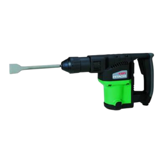
Hitachi Electric Hammer, Model H 30PV 2. MARKETING OBJECTIVE The Hitachi hammer Model H 30PV has been developed intended for faster and easier completion of light-duty jobs such as stripping mortar and tiles and allows use of SDS-plus shank tools. Main specifications are as... -
Page 5: Selling Point Descriptions
Conventional mechanism for prevention of idle hammering is to open and close the air holes according to the movement of the striker. The Model H 30PV has air holes located at the position unaffected by the rebound of the striker at no load. The air holes are opened and closed by the movement of the sleeve provided around the cylinder that interlocks with the tool and the second hammer to prevent idle hammering. -
Page 6: Specifications
5. SPECIFICATIONS Item H 30PV Power source Single-phase AC 50/60 Hz Voltage (V) 110, 120, 220, 230, 240 Motor type AC single-phase series commutator motor Insulation structure Double insulation Housing Grass-fiber reinforced resin (green) Enclosure ○ ○ ○ ○ ○... -
Page 7: Optional Accessories
5-1. Optional Accessories 5-1-1. Demolition work (1) Bull point (round type) (SDS-plus shank) (2) Bull point (square type) (SDS-plus shank) Code No. Overall length 303046 250 mm (10") 316656 250 mm (10") 5-1-2. Groove digging and edging work (1) Cold chisel (SDS-plus shank) (2) Cutter (SDS-plus shank) -
Page 8: Comparisons With Similar Products
(Note) Code numbers listed above are subject to change. Please refer to periodic Technical News Bulletins. 6. COMPARISONS WITH SIMILAR PRODUCTS 6-1. Specification Comparisons HITACHI Maker H 30PV Model name 720 (6.3 A) Power input Power output Full-load impact rate... -
Page 9: Demolishing Performance Comparisons
7. PRECAUTIONS IN SALES PROMOTION In the interest of promoting the safest and most efficient use of the Model H 30PV Hammer by all of our customers, it is very important that at the time of sale the salesperson carefully ensures that the buyer seriously recognizes the importance of the contents of the Handling Instructions, and fully understands the meaning of the precautions listed on the Caution Plate attached to each tool. -
Page 10: Grease Replacement
For Taiwan 7-3. Grease Replacement The striking portion and the speed reduction portion of the Model H 30PV respectively use different types of grease. Grease replacement is required if the unit is disassembled for maintenance or O-rings become damaged or worn as described in 7-4. -
Page 11: Reference Information
8. REFERENCE INFORMATION Structure: Piston Crank case cover Striker O-rings Crank shaft Connecting rod Second hammer Air chamber Cylinder Armature Fig. 2 8-1. Striking Operation The rotation of the armature is transferred to the crank shaft and connecting rod, which in turn cause the piston to reciprocate inside the cylinder. -
Page 12: Sealed And Dustproof Construction
Sleeve Second hammer chamber Air hole Forward movement of second hammer & striker Fig. 3 Front cap Switch handle O-ring O-ring O-ring O-ring Crank case Retainer sleeve O-ring Cylinder case Front cover seal Housing Fig. 4 8-3. Sealed and Dustproof Construction The crank case and cylinder case are sealed by five O-rings, and an oil seal which serve to prevent leakage of the grease, as well as to prevent dust and dirt from entering the mechanism. -
Page 13: Tool Retainer
8-4. Tool Retainer The Model H 30PV adopts the single-step tool retainer. Clean the shank portion of tool. (Fig. 5) Adjust the groove position by turning the tool and push it in direction until it latches itself. (Fig. 6) Check the latching by pulling on the tool. When removing the tool, pull Front Cap in direction (Fig. -
Page 14: Repair Guide
9. REPAIR GUIDE 9-1. Precautions and Suggestions for Disassembly and Reassembly of Main Body The numbers in [Bold] below correspond to the item numbers in the Parts List and exploded assembly diagrams. 9-1-1. Disassembly Retainer disassembly Remove the Front Cap [1] (since the Front Cap is made of rubber, grasp its outer face and strongly pull it to remove). - Page 15 Piston and Striker O-rings After removal of Grip (C) [8], secure the main body. Put the wrench (special repair tool J-123, Code No. 970885) on the width across flat portion of the Front Cover [10] and turn it counterclockwise to remove the Front Cover [10] (Fig.
- Page 16 Remove the four Seal Lock Hex. Socket Hd. Bolts M4 x 10 [30] from the Crank Case Cover [31] and pull the Crank Case Cover [31] upward to remove it. Remove the Connecting Rod [55] from the Crank Shaft [34]. Then the Piston [53] can be removed.
- Page 17 Hammer Holder (A) [16], the sliding portion of the Second Hammer [19], and Oil Seal (B) [39]. Seal 40 g of special grease inside the Crank Case Ass'y [35] (Connecting Rod [55] side). Apply Hitachi Motor Grease No. 29 to the Needle Bearing (HK0810) and the pinion portion of the Armature Ass'y [59]. Insert 50 g of the Hitachi Motor Grease No.
- Page 18 9-1-5. Wiring diagram For products with noise suppressor Plug (A) Switch Plug (B) Stator Noise suppressor Stator Fig. 16 For products without noise suppressor Plug (A) Plug (B) Switch Stator Stator Fig. 17 --- 15 ---...
- Page 19 9-1-6. Wiring of variable speed control switch Insert each cord into the terminal 1 and terminal 2 of the speed control switch as shown in Fig. 18 and tighten the screw [tightening torque: 0.6 0.2 N•m (6 2 kg•cm, 5.2 1.7 in-lbs.)].
-
Page 20: Standard Repair Time (Unit) Schedules
10. STANDARD REPAIR TIME (UNIT) SCHEDULES Variable 60 min. MODEL Fixed Work Flow H 30PV Housing Ass'y Stator Ass'y Gear Cover Switch Needle Bearing Cord Armature Ass'y Tail Cover Ball Bearing Bearing (6001DD) Bushing (B) Ball Bearing (608VV) Crank Case... - Page 21 LIST NO. E460 ELECTRIC TOOL PARTS LIST HAMMER 2001 • • Model H 30PV (E1)
- Page 22 PARTS H 30PV ITEM CODE NO. DESCRIPTION REMARKS USED 319-554 FRONT CAP 319-555 GRIP (A) 318-582 RETAINING RING D40 319-556 GRIP (B) 319-560 BALL SPRING (A) 319-561 BALL SPRING (B) 319-562 BALL HOLDER 319-557 GRIP (C) 959-156 STEEL BALL D7.0 (10 PCS.)
- Page 23 PARTS H 30PV ITEM CODE NO. DESCRIPTION REMARKS USED 319-582 CYLINDER 319-580 PISTON 319-581 PISTON PIN 319-585 CONNECTING ROD 600-1DD BALL BEARING 6001DDCMPS2L 971-736 WASHER (B) 319-930 360-550U ARMATURE ASS’Y 110V-115V INCLUD.56-58,72,73 360-550E ARMATURE ASS’Y 220V-230V INCLUD.58 360-550F ARMATURE ASS’Y 240V INCLUD.58...
-
Page 24: Standard Accessories
PARTS H 30PV ITEM CODE NO. DESCRIPTION REMARKS USED 500-391Z CORD (CORD ARMOR D10.1) FOR SUI 500-214Z CORD (CORD ARMOR D10.1) FOR TPE 500-249Z CORD (CORD ARMOR D8.8) FOR USA,CAN 313-092 PLUG (A) 319-595 PLUG (B) 319-596 PLUG (B) FOR USA,CAN...
Need help?
Do you have a question about the H 30PV and is the answer not in the manual?
Questions and answers