Hitachi DH 22PB Technical Data And Service Manual
Hide thumbs
Also See for DH 22PB:
- Handling instructions manual (79 pages) ,
- Instruction and safety manual (72 pages) ,
- Handling instructions manual (34 pages)

Related Manuals for Hitachi DH 22PB


Summary of Contents for Hitachi DH 22PB
- Page 1 MODEL DH 22PB Hitachi Power Tools TECHNICAL DATA ROTARY HAMMER DH 22PB SERVICE MANUAL LIST No. E481 Aug. 2004 SPECIFICATIONS AND PARTS ARE SUBJECT TO CHANGE FOR IMPROVEMENT...
- Page 2 REMARK: Throughout this TECHNICAL DATA AND SERVICE MANUAL, symbols are used in the place of company names and model names of our competitors. The symbols utilized here are as follows: Competitors Symbols Utilized Company Name Model Name GBH2-22SRE BOSCH HR2021 MAKITA HILTI...
-
Page 3: Table Of Contents
9-3. Tightening Torque ..........................23 9-4. Wiring Diagrams ..........................24 9-5. Internal Wire Arrangement and Wiring Work ..................25 9-6. Insulation Tests ..........................27 9-7. No-load Current Values ........................27 10. STANDARD REPAIR TIME (UNIT) SCHEDULES ................ 28 Assembly Diagram for DH 22PB... -
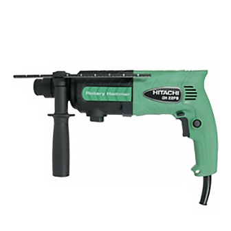
Page 4: Product Name
Hitachi Rotary Hammer, Model DH 22PB 2. MARKETING OBJECTIVE The Model DH 22PB is an evolutionary development of the Model DH 24PB, which features the concrete drilling capacity with the maximum drill bit diameter 22 mm and the use of SDS-plus shank tools. -
Page 5: Selling Points
4-1. Selling Point Descriptions 4-1-1. Class-top drilling speed The drilling speed of the Model DH 22PB is 1.8 times higher than B and 1.4 times higher than D and 1.1 times higher than C thanks to the efficient transmission of the hammering energy. -
Page 6: Specifications
5. SPECIFICATIONS 5-1. Specifications Model DH 22PB Concrete Capacity 3.4 --- 22 mm (1/8" --- 7/8") Steel 13 mm (1/2") Wood 32 mm (1-1/4") Power source AC single phase 50 Hz or 60 Hz Voltage, current and input Voltage (V) -
Page 7: Optional Accessories
5-2. Optional Accessories A. Drilling anchor holes (rotation + hammering) Drill bit (slender shaft) (2) Adapter for slender shaft (1) Drill bit (slender shaft) (SDS-plus shank) Drill bit (slender shaft) Adapter for slender shaft Outer dia. (mm) Overall length (mm) Code No. - Page 8 B. Anchor setting Anchor setting bar to permit anchor setting operation with the rotary hammer Anchor setting bar Anchor setting adapter (SDS-plus shank) Part name Overall length Part name Code No. Overall length Code No. W-1/4 Anchor setting adapter-A 302976 W-1/4 Anchor setting adapter-B 302979 W-5/16 Anchor setting adapter-A...
- Page 9 (2) Guide plate Core bit (outer diameter ) (mm) Code No. Core bit (outer diameter ) Code No. 32 (1-1/4") 50 (2") 982686 982690 35 (1-3/8") 982687 38 (1-1/2") 982688 45 (1-25/32") 982689 (3) Core bit with guide plate (The guide plate is not equipped with core bit with outer diameter of 25 mm (31/32") and 29 mm (1-5/32").) Outer diameter (mm) Code No.
- Page 10 F. Drilling hole and driving screw (rotation only) Drill chuck, chuck adapter (G), special screw and chuck wrench 13 mm (1/2") Drill chuck Chuck adapter (G) Special screw (13VLRB-D) (SDS-plus shank) (Note) If the tool is to be used for loosening screws, open the three jaws of the drill chuck and securely fix the drill chuck to chuck adapter (G) with the special screw (a left-hand threaded M6 screw) when Chuck wrench...
- Page 11 G. Driling hole (rotation only) For drilling holes in steel and wood • • • Chuck adapter (D) Drill chuck (13VLD-D) (SDS-plus shank) Chuck wrench (NOTE) The 13VLA drill chuck and chuck adapter (D) cannot be used for reverse rotation. If reverse rotation is to be used for loosening screws, use the plus bit (Bit.
-
Page 12: Comparisons With Similar Products
6. COMPARISONS WITH SIMILAR PRODUCTS 6-1. Specification Comparisons Maker Model • HITACHI Item DH 22PB 22 (7/8") 22 (7/8") 20 (15/16") 20 (15/16") Concrete 13 (1/2") 13 (1/2") 13 (1/2") 13 (1/2") Capacity Steel 20 (51/64") Wood 32 (1-1/4") 30 (1-3/16") 32 (1-1/4") -
Page 13: Drilling Speed Comparison
6-2. Drilling Speed Comparison Drilling speed varies considerably depending on the work conditions. Use the factory test results shown in Fig. 1 for comparison purpose only. Drill bit dia. (mm) Fig. 1 [Test conditions] Direction : Downward drilling Pushing force : 98 N (10 kgf) Test material : Concrete panel with a compression strength of 2,352 N/cm... -
Page 14: Precautions In Sales Promotion
7. PRECAUTIONS IN SALES PROMOTION In the interest of promoting the safest and most efficient use of the Model DH 22PB Rotary Hammer by all of our customers, it is very important that at the time of sale the salesperson carefully ensures that the buyer seriously recognizes the importance of the contents of the Handling Instructions, and fully understands the meaning of the precautions listed on the Caution Plate attached to each tool. -
Page 15: Reference Material
Model DH 22PB more compact for easier handling and operability. Thus, the appearance of the Model DH 22PB is similar to that of an impact drill. The rotation of the armature is transmitted to the second shaft via the first gear, and causes it to rotate. The second pinion provided on the second shaft engages the second gear mounted on the outer circumference of the cylinder. - Page 16 Accordingly, the armature shaft and the cylinder axis are at a right angle to each other. In the Model DH 22PB, through adoption of a spiral drive system (a mechanism using a reciprocating bearing), a more compact design has been achieved by arranging the armature shaft in parallel with the cylinder axis.
- Page 17 O-ring be replaced approximately once a year, depending on the frequency of usage of the tool. Idle hammering prevention mechanism The idle hammering prevention mechanism in the Model DH 22PB is different from that of conventional rotary hammers. When the drill bit is lifted from the concrete surface on completion of drilling, the second hammer moves to the position indicated by the continuous lines in Fig.
- Page 18 Slip mechanism The slip mechanism in the Model DH 22PB consists of a coil spring which applies a pre-set amount of pressure to ensure the interlocking of three claws provided on the flange of the cylinder (the final rotating shaft) and three matching claws provided on the face of the second gear, by which rotation is transmitted to the cylinder.
-
Page 19: Rotation Only" And "Rotation + Hammering" Changeover Mechanism
8-3. "Rotation Only" and "Rotation + Hammering" Changeover Mechanism The change lever on the Model DH 22PB permits quick and easy changeover between the "Rotation Only" and "Rotation + Hammering" functions. When operating the change lever, be sure to continue pressing the pushing button. -
Page 20: Drill Bits
8-5. Drill Bits The chuck section is designed exclusively for the popular and widely available SDS-plus shank bits, as shown in Fig. 4. Rotating torque is transmitted to the drill bit by two key rails provided in the tool holding section. A steel ball is used to prevent the bit from falling out. -
Page 21: Chuck Section
8-7. Dust Collector (B) When drilling holes overhead, dust collector (B) can be mounted on the Model DH 22PB to prevent dust and chips from falling downward. Dust collector (B) is intended solely for use when drilling holes in concrete, and cannot be used for drilling holes in steel or wood. - Page 22 Approx. 72 mm (2-27/32") Approx. 16 mm (5/8") Grip (on the main body side) Drill bit length = 166 mm Drill bit length = 110 mm Socket adapter (B) Seal cover Socket Dust cover Retaining ring for D30 shaft Outer race Washer Steel Ball D6.35 Fig.
-
Page 23: Precautions In Disassembly And Reassembly
9. PRECAUTIONS IN DISASSEMBLY AND REASSEMBLY The numbers in [Bold] correspond to the item numbers in the Parts List and exploded assembly diagrams. 9-1. Disassembly (1) Disassembly of the striking mechanism section Push in the Second Hammer [27] with a drill bit or a screwdriver. Remove the Striker [35] chucked by O-ring (C) [32]. - Page 24 (2) Disassembly of the tool retainer Slide the Grip [3] fully in the arrow direction as shown in Fig. 9 and remove the Front Cap [1]. Pulling the Grip [3] as shown in Fig. 10, remove the Stopper Ring [2] with a retaining ring puller. Then the Grip [3], Ball Holder [4], Steel Ball D7.0 [21], Holder Plate [5], Holder Spring [6] and Washer (B) [7] can be removed from the Cylinder [22].
-
Page 25: Reassembly
Apply Molub Alloy No. 777-1 grease to the outer circumference of the Clutch [47] groove and the pin portion of the Change Lever [14]. Apply Hitachi Motor Grease No. 29 to the O-ring (S-18) [15] for the Steel Ball D7.0 [21] and the Change Lever [14]. -
Page 26: Tightening Torque
Change Lever [14] Pushing Button [12] Fig. 12 (3) Press-fitting the first gear Press-fit the First Gear [49] aligning with the shaft end surface of the Second Shaft [44]. After press-fitting the First Gear [49], check that the inside ring of the Reciprocating Bearing [48] turns smoothly. (4) Reassembly of the oil seal Prior to reassembly, apply grease to the inner circumference of the Oil Seal [16]. -
Page 27: Wiring Diagrams
9-4. Wiring Diagrams (1) Products with noise suppressor Forward-reverse changeover switch Variable speed switch Stator Blue White Gray Noise Choke coil suppressor Cord Choke coil Brown Black Stator Fig. 14 (2) Products without noise suppressor Forward-reverse changeover switch Variable speed switch Stator Blue Gray... -
Page 28: Internal Wire Arrangement And Wiring Work
9-5. Internal Wire Arrangement and Wiring Work A. Internal wire arrangement (1) Product with noise suppressor Brown (Choke coil) Choke Coil Gray (Stator) (Brown) [70] Choke Coil (Blue) [71] Black (Stator) Blue (Choke coil) White (Stator) Red (Stator) Noise Suppressor [74] Fig. - Page 29 (2) Product without noise suppressor Brown (CB) Gray (Stator) Support (B) [72] Support (B) [72] Black (Stator) Blue (CB) White (Stator) Red (Stator) Fig. 17 --- 26 ---...
-
Page 30: Insulation Tests
B. Additional wiring work (Stator) (CB or choke coil) General internal wiring can be accomplished by referring to paragraphs 9-4 and 9-5-A. The following are special instructions for switch connection. (1) Wiring of reversing switch Insert the lead wire (black) coming from the stator into the terminal (1) of the reversing switch, and the lead wire (white) into the terminal (2) as shown in Fig. -
Page 31: Standard Repair Time (Unit) Schedules
10. STANDARD REPAIR TIME (UNIT) SCHEDULES Variable 60 min. MODEL Fixed DH 22PB Work Flow Switch Handle Cover Cord Cord Armor Housing Stator Armature O-ring (P-22) Ball Bearing (608DD) Ball Bearing (608VV) General Assembly Front Cap Second Hammer Cylinder Grip... - Page 32 Hitachi Power Tools LIST NO. E481 ELECTRIC TOOL PARTS LIST ROTARY HAMMER 2004 • • Model DH 22PB (E1)
- Page 33 PARTS DH 22PB ITEM CODE NO. DESCRIPTION REMARKS USED 306-345 FRONT CAP 306-340 STOPPER RING 322-809 GRIP 322-810 BALL HOLDER 322-811 HOLDER PLATE 322-812 HOLDER SPRING 984-118 WASHER (B) 939-547 RETAINING RING FOR D20 SHAFT (10 PCS.) 301-654 TAPPING SCREW (W/FLANGE) D5X35...
- Page 34 PARTS DH 22PB ITEM CODE NO. REMARKS DESCRIPTION USED 322-816 FELT PACKING 876-796 O-RING (P-22) 322-818 PACKING WASHER 608-DDM BALL BEARING 608DDC2PS2L 982-631 WASHER (A) 360-650U ARMATURE ASS’Y 110V-120V 1 INCLUD. 55, 56, 61 360-650E ARMATURE 220V-230V 360-650F ARMATURE 240V...
- Page 35 PARTS DH 22PB ITEM CODE NO. DESCRIPTION REMARKS USED 500-440Z CORD 1 (CORD ARMOR D8.8) FOR HKG 500-391Z CORD 1 (CORD ARMOR D8.8) FOR SUI 500-454Z CORD 1 (CORD ARMOR D8.8) FOR GBR (110V) 500-446Z CORD 1 (CORD ARMOR D8.8) FOR GBR (230V) 500-456Z CORD 1 (CORD ARMOR D8.8) FOR CHN...
-
Page 36: Standard Accessories
STANDARD ACCESSORIES DH 22PB ITEM CODE NO. DESCRIPTION REMARKS USED 323-130 CASE 303-659 SIDE HANDLE 303-709 DEPTH GAUGE 310-331 DEPTH GAUGE FOR USA, CAN 303-624 CHUCK ADAPTER (D) (SDS PLUS) FOR AUS OPTIONAL ACCESSORIES ITEM CODE NO. DESCRIPTION REMARKS USED 980-927 GREASE FOR HAMMER. - Page 37 OPTIONAL ACCESSORIES DH 22PB ITEM CODE NO. DESCRIPTION REMARKS USED 971-798 ANCHOR SETTING ADAPTER A W5/8” (MANUAL) 971-799 ANCHOR SETTING ADAPTER B W1/4” (MANUAL) 971-800 ANCHOR SETTING ADAPTER B W5/16” (MANUAL) 971-801 ANCHOR SETTING ADAPTER B W3/8” (MANUAL) 971-802 ANCHOR SETTING ADAPTER B W1/2” (MANUAL) 971-803 ANCHOR SETTING ADAPTER B W5/8”...
Need help?
Do you have a question about the DH 22PB and is the answer not in the manual?
Questions and answers