Table of Contents
Advertisement
QQ
3 7 63 1515 0
SERVICE MANUAL
TE
L 13942296513
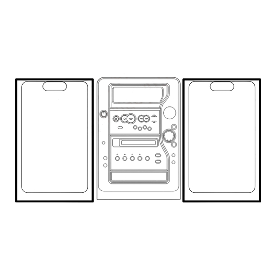
MD/CD STEREO
SYSTEM
If requiring information about the MD mechanism, see Service Manual of AZG-4YA,
(S/M Code No.09-001-341-2N2).
www
.
http://www.xiaoyu163.com
x
ao
u163
y
i
S/M Code No. 09-00A-351-2N1
http://www.xiaoyu163.com
XR-MDK505
2 9
8
Q Q
3
6 7
1 3
1 5
BASIC TAPE MECHANISM : 2ZM-1 R11NM
BASIC CD MECHANISM : 3ZG-3 E3NM
BASIC MD MECHANISM : AZG-4 YA
co
.
HRJ(S)
9 4
2 8
0 5
8
2 9
9 4
2 8
m
9 9
9 9
Advertisement
Table of Contents

Related Manuals for Aiwa SX-M510 Y


Summary of Contents for Aiwa SX-M510 Y
- Page 1 http://www.xiaoyu163.com XR-MDK505 HRJ(S) 3 7 63 1515 0 SERVICE MANUAL L 13942296513 BASIC TAPE MECHANISM : 2ZM-1 R11NM MD/CD STEREO BASIC CD MECHANISM : 3ZG-3 E3NM SYSTEM BASIC MD MECHANISM : AZG-4 YA If requiring information about the MD mechanism, see Service Manual of AZG-4YA, (S/M Code No.09-001-341-2N2).
-
Page 2: Table Of Contents
http://www.xiaoyu163.com TABLE OF CONTENTS 3 7 63 1515 0 SPECIFICATIONS ................................... 2 ACCESSORIES LIST ..................................4 PROTECTION OF EYES FROM LASER BEAM DURING SERVING .................... 5 DISASSEMBLY INSTRUCTIONS ............................. 6 ~ 9 SERVICE JIG AND TOOLS ................................10 NOTES DURING RE-ASSEMBLING ............................11 CD TEST MODE ................................... -
Page 3: Specifications
http://www.xiaoyu163.com SPECIFICATIONS 3 7 63 1515 0 L 13942296513 • Design and specifications are subject to change without notice. • The word “BBE” and the “BBE symbol” are trademarks of BBE Sound, Inc. • Under license from BBE Sound, Inc. •... -
Page 4: Accessories List
http://www.xiaoyu163.com ACCESSORIES LIST 3 7 63 1515 0 REF. NO PART NO. KANRI DESCRIPTION 1 8A-CB4-901-010 IB,H(EC)M 2 8A-CB4-951-010 RC UNIT,RC-AAT18 3 87-006-225-010 AM LOOP ANT NC2 4 87-043-115-010 ANT,FEEDER FM 5 87-050-103-010 CORD,PIN 1PY1.5M 6 87-A91-017-010 PLUG,CONVERSION JT-0476 L 13942296513 u163 http://www.xiaoyu163.com... -
Page 5: Protection Of Eyes From Laser Beam During Serving
http://www.xiaoyu163.com PROTECTION OF EYES FROM LASER BEAM DURING SERVICING 3 7 63 1515 0 CAUTION This set employs laser. Therefore, be sure to follow carefully the instructions below when servicing. Use of controls or adjustments or performance of proce- dures other than those specified herin may result in WARNING!! hazardous radiation exposure. -
Page 6: Disassembly Instructions
http://www.xiaoyu163.com DISASSEMBLY INSTRUCTION -1/4 3 7 63 1515 0 1. Removing the outside appearance parts 1) Remove the six screws ( 1 -4, 2 -2) and remove the PANEL, SIDE R. PANEL, SIDE R 2) Remove the six screws ( 1 -4, 2 -2) and remove the PANEL, SIDE L. PANEL, SIDE L L 13942296513 3) Remove the three screw 1 and lift up the PANEL, TOP ASSY 2 . - Page 7 http://www.xiaoyu163.com DISASSEMBLY INSTRUCTION -2/4 3 7 63 1515 0 5) Remove the 12 screws and remove the CABI, REAR. Remove the connector from FAN from MAIN C.B. CABI, REAR 6) This is the state after the outside appearance parts are removed. L 13942296513 2.
- Page 8 http://www.xiaoyu163.com DISASSEMBLY INSTRUCTION -3/4 3 7 63 1515 0 2) Remove the screw 1 and remove the PWB, MAIN ASSY in the direction of the arrow 2 . (The board is hooked.While lifting up the HOOK, remove the board.) PWB,MAIN ASSY HOOK 4.
-
Page 9: Disassembly Instructions
http://www.xiaoyu163.com DISASSEMBLY INSTRUCTION -4/4 3 7 63 1515 0 4) This is the state after the PWB, MAIN ASSY and CABI, FRONT ASSY are removed. 5. Removing the MD block (AZG-4) 1) Remove the four screws and remove the MD block. AZG-4 L 13942296513 6. -
Page 10: Service Jig And Tools
http://www.xiaoyu163.com 3 7 63 1515 0 SERVICE JIG AND TOOLS Using the FFC for extension enables the CD/MD mechanism to be repaired when the power supply is turned on. (Refer to the below figure.) 1 FFC, 8P-1.25 88-908-401-110 2 FFC, 8P-1.0 SV-J00-043-010 3 FFC, 14P-1.0 SV-J00-044-010 L 13942296513 u163... -
Page 11: Notes During Re-Assembling
http://www.xiaoyu163.com NOTES DURING RE-ASSEMBLING 3 7 63 1515 0 When assemble the magical change panel, adjust the phase of the gear. 1. Phase adjustment of the GEAR, OPE 1 and GEAR, WORM WHEEL. 1) Align holes 1 . 2) Then, move the position of the holes of each gear as shown by 2 in the illustration. HLDR,GEAR GEAR,WORM WHEEL GEAR,OPE 1... -
Page 12: Cd Test Mode
http://www.xiaoyu163.com CD TEST MODE 3 7 63 1515 0 1. How to Active CD Test Mode While pressing the CD function button, insert the AC plug to the outlet. When the test mode starts, all indicators in the display will light. 2. -
Page 13: Md Test Mode - 1/14
http://www.xiaoyu163.com MD TEST MODE - 1/14 3 7 63 1515 0 Key Operation in Test Mode and MD Electrical Adjustment: After the test mode has started, the operation panel will not turn. Perform key operation using either of the following procedures: •... - Page 14 http://www.xiaoyu163.com MD TEST MODE - 2/14 3 7 63 1515 0 2. Checking MD Test Mode and Audio Output 1) After the test mode has started, the display will be as follows, and the test mode can be used. 2) Checking audio output A 1kHz, -17dB (140mV) signal is output from the MD mechanism output (D/A OUT).
- Page 15 http://www.xiaoyu163.com MD TEST MODE - 3/14 3 7 63 1515 0 7. Checking Loading Mechanism Operation and Detection Switch 7-1 Checking loading mechanism operation Each time the CD → MD key or MD EJECT key is pressed after MO disc is inserted in the “ALL SV OFF” status, OWH can be moved down or up.
- Page 16 http://www.xiaoyu163.com MD TEST MODE - 4/14 3 7 63 1515 0 8-3 Checking focus servo and sled error (EF balance) 1) Insert disc. 2) Press the MD MODE key to set the disc mode as follows to match the disc. •...
- Page 17 http://www.xiaoyu163.com MD TEST MODE - 5/14 3 7 63 1515 0 2) Refer to the adjustment item for recording/playback error rate. Press the T-BASS key on remote control: The recording address can be switched: Pressing T-BASS while “ALL SV OFF” is lit in the display will switch the address between 600C and 30C (nothing will light in the display).
- Page 18 http://www.xiaoyu163.com MD TEST MODE - 6/14 3 7 63 1515 0 MD Electrical Adjustment Perform all adjustments and checks of MD block in the test mode. If “NO Adjust” lights in the display, perform all adjustments. * For key operation, refer to “Key operation in test mode and MD electrical adjustment”. Test equipment and jigs: Thermometer (centigrade display), laser power meter (measurable up to 10 mW), test disc: TGYS-1 (or prerecorded disc), MDW-74 (or equivalent)
- Page 19 http://www.xiaoyu163.com MD TEST MODE - 7/14 3 7 63 1515 0 Adjustment Procedure Flowchart START Starting TEST MODE While holding “MD” function key, plug the power cord into AC outlet. “STOP” Initializing EEPROM L 13942296513 While holding down “CD OPEN/CLOSE”, press “MD EDIT”. To next item u163 -19-...
- Page 20 http://www.xiaoyu163.com MD TEST MODE - 8/14 3 7 63 1515 0 The temperature of PWB must match the Thermal Compensation Adjustment room temperature for this adjustment. “DISPLAY” “PAUSE” Thermal compensation adjustment Use thermometer (centigrade display) to measure the temperature around the MD mechanism, compare the display with the thermometer, and then “B.SKIP F.SKIP”...
- Page 21 http://www.xiaoyu163.com MD TEST MODE - 9/14 3 7 63 1515 0 Laser Power Check Write power check Read power check Press “MD EDIT” twice. “MD EDIT” “PAUSE” Checking write power set value “PAUSE” Make sure that it is “$9F”. Checking read power set value “ENTER”...
- Page 22 http://www.xiaoyu163.com MD TEST MODE - 10/14 3 7 63 1515 0 Auto Sequence Adjustment MO disc adjustment “STOP” Load MDW-74. Press “DISPLAY” twice. “MD MODE” Checking adjustment values (IVR, EF balance) “TIME MARK” lights EF balance value check Within 09-15 (hexadecimal) “MD”...
- Page 23 http://www.xiaoyu163.com MD TEST MODE - 11/14 3 7 63 1515 0 (continued) Auto Sequence Adjustment PIT disc adjustment PIT disc checking adjustment values “STOP” Load TGYS-1. Press “DISPLA” twice. “MD MODE” Checking adjustment values (IVR, EF balance) “AUTO MARK” lights EF balance value check Within 09-15 (hexadecimal) “MD FUNCTION”...
- Page 24 http://www.xiaoyu163.com MD TEST MODE - 12/14 3 7 63 1515 0 Error Rate Check Playback error rate check “DISPLAY” Playback error rate check Load TGYS-1. 0030 or less “MD MODE” “AUTO MARK” lights. “STOP” “B.SKIP F.SKIP” “MD EJECT” L 13942296513 To move the pickup to the middle position of disc Remove the disc.
- Page 25 http://www.xiaoyu163.com MD TEST MODE - 13/14 3 7 63 1515 0 (continued) Error Rate Check Recording/playback error rate check Address display Recording starts automatically from 600C. Make a recording of approx. 15-30 seconds. Load MDW-74. “STOP” “MD MODE” “TIME MARK” lights. “AUX/D-IN”...
- Page 26 http://www.xiaoyu163.com MD TEST MODE - 14/14 3 7 63 1515 0 Check After Adjustment is Complete Press “POWER” twice, and make sure that “No Adjus” does not light when power is on. L 13942296513 u163 -26- http://www.xiaoyu163.com...
-
Page 27: Electrical Main Parts List - 1/7
http://www.xiaoyu163.com ELECTRICAL MAIN PARTS LIST - 1/7 3 7 63 1515 0 REF. NO PART NO. KANRI DESCRIPTION REF. NO PART NO. KANRI DESCRIPTION 87-026-470-080 C-TR,HN1C03FB 87-A30-427-080 C-TR,DTC114EKA 87-020-454-010 IC,DN6851 87-A20-547-010 C-IC,CXA1992AR 87-A21-021-040 C-IC,BU2099FV DIODE 87-A21-573-010 IC,SPS-448-1-E 87-A20-455-010 IC,HA12211 87-020-465-080 DIODE,1SS133 (110MA) 87-A40-270-080 C-DIODE,MC2838... - Page 28 http://www.xiaoyu163.com ELECTRICAL MAIN PARTS LIST - 2/7 3 7 63 1515 0 REF. NO PART NO. KANRI DESCRIPTION REF. NO PART NO. KANRI DESCRIPTION C203 87-A10-946-080 C-CAP,S 220P-100 J CH C388 87-012-156-080 C-CAP,S 220P-50 CH C204 87-A10-946-080 C-CAP,S 220P-100 J CH C389 87-010-380-080 CAP, ELECT 47-16V...
- Page 29 http://www.xiaoyu163.com ELECTRICAL MAIN PARTS LIST - 3/7 3 7 63 1515 0 REF. NO PART NO. KANRI DESCRIPTION REF. NO PART NO. KANRI DESCRIPTION C708 87-010-213-080 C-CAP,S 0.015-25 B L202 87-003-383-010 COIL,1UH-S C709 87-010-213-080 C-CAP,S 0.015-25 B L203 87-003-098-080 COIL,2.2UH C710 87-010-197-080 CAP, CHIP 0.01 DM...
- Page 30 http://www.xiaoyu163.com ELECTRICAL MAIN PARTS LIST - 4/7 3 7 63 1515 0 REF. NO PART NO. KANRI DESCRIPTION REF. NO PART NO. KANRI DESCRIPTION L201 87-A50-333-010 COIL,OSC 9.43MHZ C140 87-016-044-040 CAP,E 100-16 R301 87-022-341-080 C-RES,S 560-1/10W F C141 87-010-196-080 CHIP CAPACITOR,0.1-25 R302 87-022-341-080 C-RES,S 560-1/10W F...
- Page 31 http://www.xiaoyu163.com ELECTRICAL MAIN PARTS LIST - 5/7 3 7 63 1515 0 REF. NO PART NO. KANRI DESCRIPTION REF. NO PART NO. KANRI DESCRIPTION C532 87-010-553-040 CAP,E 47-16 GAS R131 87-022-360-080 C-RES,S 39K-1/10W F C533 87-010-197-080 CAP, CHIP 0.01 DM R132 87-022-360-080 C-RES,S 39K-1/10W F...
- Page 32 http://www.xiaoyu163.com ELECTRICAL MAIN PARTS LIST - 6/7 3 7 63 1515 0 REF. NO PART NO. KANRI DESCRIPTION REF. NO PART NO. KANRI DESCRIPTION CON301 8A-CJ4-647-010 CONN ASSY,7P V RPH SHILD C851 87-010-197-080 CAP, CHIP 0.01 DM C852 87-010-197-080 CAP, CHIP 0.01 DM CN802 87-A60-622-010 CONN,5P V 2MM JMT...
-
Page 33: Electrical Main Parts List
http://www.xiaoyu163.com ELECTRICAL MAIN PARTS LIST - 7/7 3 7 63 1515 0 REF. NO PART NO. KANRI DESCRIPTION C0777 87-010-400-080 CAP,E 0.47-50 M 11L SME C0778 87-010-401-080 CAP,E 1-50 M 11L SME C0779 87-010-401-080 CAP,E 1-50 M 11L SME C0780 87-010-196-080 C-CAP,S 0.1-25 Z F C2012 C0781... -
Page 34: Transistor Illustration
http://www.xiaoyu163.com TRANSISTOR ILLUSTRATION 3 7 63 1515 0 E C B E C B B C E B C E 2SA1357 2SA1162 CC5551 2SB1370 2SB1625 CSA1585 2SD2494 2SA1235 CSB1058 2SC2712 CSC4115 2SC2714 CSD655 2SC3052 2SD1306 KTA1266 CMBT5401 KTC3198 CMBT5551 DTA114EK DTA123EK DTA123JK DTA124XK... -
Page 35: Schematic Diagram - 1 (Main Section)
http://www.xiaoyu163.com SCHEMATIC DIAGRAM - 1 (MAIN SECTION) 3 7 6 3 1 5 1 5 0 1 3 9 4 2 2 9 6 5 1 3 27.7 -28.4 5.25 27.7 w w w u 1 6 3 47/50 -35- http://www.xiaoyu163.com... -
Page 36: Wiring - 1 (Main C.b)
http://www.xiaoyu163.com WIRING - 1 (MAIN C.B) 3 7 6 3 1 5 1 5 0 1 3 9 4 2 2 9 6 5 1 3 w w w u 1 6 3 -36-... -
Page 37: Wiring - 2 (Pt 1, 2 C.b)
http://www.xiaoyu163.com WIRING - 2 (PT1, 2 C.B) 3 7 6 3 1 5 1 5 0 1 3 9 4 2 2 9 6 5 1 3 w w w u 1 6 3 -37-... -
Page 38: Schematic Diagram - 2 (Front Section)
http://www.xiaoyu163.com SCHEMATIC DIAGRAM - 2 (FRONT SECTION) 3 7 6 3 1 5 1 5 0 1 3 9 4 2 2 9 6 5 1 3 O-CLK I-SW O-OPEN O-CLOSE COMMAND DMUTE I/OBUSY STATUS MD1 EXT-DIN MD2 ACLK MD4 SIN MD3 SOUT MD5 ARDY MD6 MREQ... -
Page 39: Wiring - 3 (Front, Switch-1,2 C.b)
http://www.xiaoyu163.com WIRING - 3 (FRONT, SWITCH-1, 2 C.B) 3 7 6 3 1 5 1 5 0 JR206 1 3 9 4 2 2 9 6 5 1 3 w w w u 1 6 3 -39-... -
Page 40: Wiring - 4 (Face-A,B,C C.b)
http://www.xiaoyu163.com WIRING - 4 (FACE-A,B,C C.B) 3 7 6 3 1 5 1 5 0 JR801 JR809 1 3 9 4 2 2 9 6 5 1 3 JR815 JR825 JR813 w w w u 1 6 3 -40-... -
Page 41: Schematic Diagram - 3 (Vcd - 1/2 Section)
http://www.xiaoyu163.com SCHEMATIC DIAGRAM - 3 (VCD-1/2 SECTION) 3 7 6 3 1 5 1 5 0 2.46 1 3 9 4 2 2 9 6 5 1 3 11.86 2.65 2.65 w w w u 1 6 3 -41- http://www.xiaoyu163.com... -
Page 42: Schematic Diagram - 4 (Vcd - 2/2 Section)
http://www.xiaoyu163.com SCHEMATIC DIAGRAM - 4 (VCD-2/2 SECTION) 3 7 6 3 1 5 1 5 0 1 3 9 4 2 2 9 6 5 1 3 w w w u 1 6 3 -42- http://www.xiaoyu163.com... -
Page 43: Wiring - 5 (Vcd, Video Out, Cd Load,Cd Drive C.b)
http://www.xiaoyu163.com WIRING - 5 (VCD, VIDEO OUT, CD LOAD, CD DRIVE C.B) 3 7 6 3 1 5 1 5 0 X501 1 3 9 4 2 2 9 6 5 1 3 J801 w w w u 1 6 3 -43-... -
Page 44: Wiring - 6 (Deck, Relay C.b)
http://www.xiaoyu163.com WIRING - 6 (DECK, RELAY C.B) 3 7 63 1515 0 L 13942296513 u163 -44-... -
Page 45: Schematic Diagram - 5 (Tuner Section)
http://www.xiaoyu163.com SCHEMATIC DIAGRAM - 5 (TUNER SECTION) 3 7 6 3 1 5 1 5 0 FEMUNM 1 3 9 4 2 2 9 6 5 1 3 w w w u 1 6 3 -45- http://www.xiaoyu163.com... -
Page 46: Wiring - 7 (Tuner C.b)
http://www.xiaoyu163.com WIRING - 7 (TUNER C.B) 3 7 6 3 1 5 1 5 0 1 3 9 4 2 2 9 6 5 1 3 w w w u 1 6 3 -46-... -
Page 47: Ic Block Diagram - 1/5
http://www.xiaoyu163.com IC BLOCK DIAGRAM - 1/5 3 7 63 1515 0 IC, BU2099FV IC, BU2092F IC, MM1454XFBE VREF L 13942296513 QSurround BIAS ROUT LOUT IC, M5291FP IC, TA7291S VREF OUT(+) OUT(-) PROTECT CIRCUIT u163 OPEN CLOSE -47- http://www.xiaoyu163.com... - Page 48 http://www.xiaoyu163.com IC BLOCK DIAGRAM - 2/5 3 7 63 1515 0 IC, LH5V2RN1 IC, BA5915FP MEMORY MATRIX (262.144 X 8bit) T.S.D 6.65k 6.65k ADDRESS ADDRESS LEVEL SHIFT LEVEL SHIFT BUFFER DECODER LEVEL SHIFT LEVEL SHIFT 6.65k 6.65k COLUMN SELECT MUTE TIMING BUFFER SENSE AMP...
- Page 49 http://www.xiaoyu163.com IC BLOCK DIAGRAM - 3/5 3 7 63 1515 0 IC, LA1837NL L 13942296513 IC, HA12211 u163 -49- http://www.xiaoyu163.com...
- Page 50 http://www.xiaoyu163.com IC BLOCK DIAGRAM - 4/5 3 7 63 1515 0 IC, CXA1553P IC, LC72131D L 13942296513 u163 -50- http://www.xiaoyu163.com...
- Page 51 http://www.xiaoyu163.com IC BLOCK DIAGRAM - 5/5 3 7 63 1515 0 IC, BD3876AKS2 IC, M658474AFP L 13942296513 IC, BU9262AFS IC, SN74LV74APW 1PRE 1CLK 1CLR 2PRE 2CLK 2CLR 10 4 11 3 u163 12 2 13 1 -51- http://www.xiaoyu163.com...
-
Page 52: Ic Description
http://www.xiaoyu163.com IC DESCRIPTION - 1/7 (CXA1992AR)-1/2 3 7 63 1515 0 Pin No. Pin Name Description Output terminal for focus error amplifier. Internally connected to window comparator input for bias condition. Input terminal for focus error. FDFCT Capacitor connection terminal for time constant used when there is defect. This pin is connected to GND via capacitor when high frequency gain of the focus servo is attenuated. - Page 53 http://www.xiaoyu163.com IC DESCRIPTION - 1/7 (CXA1992AR)-2/2 3 7 63 1515 0 Pin No. Pin Name Description Anti-reverse input terminal for RF summing amplifier. The gain of RF amplifier is decided by the connection resistance between RF-M and RF-O terminals. RFTC This is a pin where the selection time constant is externally connected to control the RF level.
- Page 54 http://www.xiaoyu163.com IC DESCRIPTION - 2/7 (LC876572V-5S43)-1/2 3 7 63 1515 0 Pin No. Pin Name Description _________ I-STEREO/I-DRF MONO/STE change O-BEEP Beep output for panel turn control I-RDSDATA/O-CD-CE RDS DATA/CD latch output I-TUDO/I-SUBQ Tuner ON/CD SUBQ data input O-MSTB Main IC control output O-CLK Clock output to TUNER PLL IC (LC72131D).
- Page 55 http://www.xiaoyu163.com IC DESCRIPTION - 2/7 (LC876572V-5S43)-2/2 3 7 63 1515 0 Pin No. Pin Name Description B3/P11 Tuner suffix change/for FL output B2/P10 Tuner suffix change/for FL output B1/P9 Tuner suffix change/for FL output VDD4 – Power supply (+5.6V). For FL output For FL output D/P6 Turn panel D/for FL output...
- Page 56 http://www.xiaoyu163.com IC DESCRIPTION -3/7 (CL680-D1)-1/3 3 7 63 1515 0 Pin No. Pin Name Description — No connection. — Ground Bit clock input from CD DSP. CD BCK CD DATA Data input from CD DSP. CD LRCK LRCK input from CD DSP. CD C2PO C2 pointer input from CD DSP.
- Page 57 http://www.xiaoyu163.com IC DESCRIPTION - 3/7 (CL680-D1)-2/3 3 7 63 1515 0 Pin No. Pin Name Description Y OUT Video signal “Y” OUT. AVDD DAC — Analog power supply (DAC) 3.3V. AGND DAC — Analog ground. R REF Reference resistor input. V REF Voltage reference input.
- Page 58 http://www.xiaoyu163.com IC DESCRIPTION - 3/7 (CL680-D1)-3/3 3 7 63 1515 0 Pin No. Pin Name Description HINT Micon interface. (Host interrupt) CDG SCK CD-G serial clock input. — Ground. Micon interface. (Host clock) VDD3 — Power supply 3.3V. HD IN Micon interface.
- Page 59 http://www.xiaoyu163.com IC DESCRIPTION - 4/7 (CXD2540Q-1/2)-1/3 3 7 63 1515 0 Pin No. Pin Name Description Focus OK input. Used for SENS output and the servo auto sequencer. Spindle motor output filter switching output. Spindle motor on/off control output. Spindle motor servo control. High, when sampled value of GFS at 460Hz is high.
- Page 60 http://www.xiaoyu163.com IC DESCRIPTION - 4/7 (CXD2540Q-1/2)-2/3 3 7 63 1515 0 Pin No. Pin Name Description GTOP DA11 output when PSSL=1. GTOP output when PSSL=0. XVCF DA10 output when PSSL=1. XVCF output when PSSL=0. XPCLK DA09 output when PSSL=1. XPLCK output when PSSL=0. DA08 output when PSSL=1.
- Page 61 http://www.xiaoyu163.com IC DESCRIPTION - 4/7 (CXD2540Q-1/2)-3/3 3 7 63 1515 0 Pin No. Pin Name Description DATO Serial data output to SSP. XLTO Serial data latch output to SSP. Latched at the falling edge. CLKO Serial data transfer clock output to SSP. Mirror signal input.
- Page 62 http://www.xiaoyu163.com IC DESCRIPTION - 5/7 (LC74781M-9017)-1/2 3 7 63 1515 0 Pin No. Pin Name Description VSS1 — GND connection terminal. (Digital ground terminal). Xtal IN External X’tal and capacitor for internal sync generator, or the external clock are connected to this terminal.
- Page 63 http://www.xiaoyu163.com IC DESCRIPTION - 5/7 (LC74781M-9017)-2/2 3 7 63 1515 0 Pin No. Pin Name Description System reset input terminal. Pull-up resistor is built-in. (Hysteresis input). VDD1 — Power supply. (+5V digital power supply). L 13942296513 u163 -63- http://www.xiaoyu163.com...
- Page 64 http://www.xiaoyu163.com IC DESCRIPTION - 6/7 (SM5878AM)-1/1 3 7 63 1515 0 Pin No. Pin Name Description MODE = H: Soft mute ON/OFF terminal. (Mute at H). MUTE MODE = L: Attenuator level DOWN/UP terminal. (DOWN at H). De-emphasis ON/OFF terminal. (De-emphasis ON at H). DEEM MCKI Oscillator clock output.
- Page 65 http://www.xiaoyu163.com IC DESCRIPTION - 7/7 (µPD78016FGC)-1/2 3 7 63 1515 0 Pin No. Pin Name Description RBPLS RADIAL BALANCE PLUS. AMUTE AUDIO ANALOG MUTE (H=MUTE ON). GFS. XVCDMD AUDIO/VIDEO CD MODE (L=VCD=SPINDLE GAIN UP). DOUT MUTE CONT. EMPH EMPHASIS. SQSO SQDATA FROM CD.
- Page 66 http://www.xiaoyu163.com IC DESCRIPTION - 7/7 (µPD78016FGC)-2/2 3 7 63 1515 0 Pin No. Pin Name Description 8.0MHz CERALOCK. — Ground — Not used. 5.0VDD. AVSS — Ground XMPGRST MPEG BLOCK IC RESET. HSEL ADDRESS/DATA SEL TO CL680. INLSW INSIDE LIMIT SW . —...
-
Page 67: Fldisplay 1/2
http://www.xiaoyu163.com FLDISPLAY 1/2 3 7 63 1515 0 GRID ASSIGNMENT L 13942296513 u163 -67- http://www.xiaoyu163.com... - Page 68 http://www.xiaoyu163.com FL DISPLAY 2/2 ANODE CONNECTION 3 7 63 1515 0 L 13942296513 u163 -68- http://www.xiaoyu163.com...
-
Page 69: Adjustment(Tuner/Deck/Main)
http://www.xiaoyu163.com ADJUSTMENT -1/3 3 7 63 1515 0 <TUNER SECTION> TUNER C.B CN701 (LCH) (GND) (RCH) L981 TP3(DC) TP4(DC) TP2(CLK) IC771 L771 L772 FFE801 TP1(VT) L 13942296513 1. Clock Frequency Check 5. FM VT Check Settings : • Test point : TP2 (CLK) Settings : •... - Page 70 http://www.xiaoyu163.com ADJUSTMENT -2/3 3 7 63 1515 0 <DECK, FRONT SECTION> MAIN C.B SFR352 SFR351 SFR304 SFR303 SFR306 SFR305 L 13942296513 DECK C.B DECK R / P / E HEAD CON1 SFR1 u163 -70- http://www.xiaoyu163.com...
- Page 71 http://www.xiaoyu163.com ADJUSTMENT -3/3 3 7 63 1515 0 FRONT C.B IC201 (K-SCAN) L201 < DECK SECTION > 1. Tape Speed Adjustment 5. REC/PB Frequency Response Adjustment Settings : • Test tape : TTA–100 Settings : • Test tape : TTA–602 L 13942296513 •...
-
Page 72: Mechanical Exploded View 1/1
http://www.xiaoyu163.com MECHANICAL EXPLODED VIEW 1/1 3 7 6 3 1 5 1 5 0 HT-SINK PWB PWB WIRE,BINDER AZG-4 45 46 2ZM-1 PLATE,SHLD P.C.B 23 24 1 3 9 4 2 2 9 6 5 1 3 P.C.B SHIELD, P.C.B PLATE 3ZG-3 w w w... -
Page 73: Mechanical Main Parts List 1/1
http://www.xiaoyu163.com MECHANICAL MAIN PARTS LIST 1/1 3 7 63 1515 0 REF. NO PART NO. KANRI DESCRIPTION REF. NO PART NO. KANRI DESCRIPTION 1 8A-CJ4-042-010 WINDOW,SENSOR 46 8A-CJ4-205-110 GEAR,WORM-WHEEL 2 8A-CJ4-017-010 KNOB,RTRY JOG 47 86-ZG1-232-010 SPR-P,WORM 3 8A-CJ4-016-110 KNOB,RTRY MAIN 48 81-ZG1-212-010 PULLY,LOAD MO 4 8A-CB4-001-010... -
Page 74: Color Name List
http://www.xiaoyu163.com COLOR NAME TABLE 3 7 63 1515 0 COLOR NAME TABLE Basic color symbol Color Basic color symbol Color Basic color symbol Color Black Cream Orange Green Gray Blue Transparent Blue Gold Pink Silver Titan Silver Brown Violet White Transparent White Yellow Transparent Yellow... -
Page 75: Tape Mechanism Exploded View 1/1 <2Zm-1 R11Nm
http://www.xiaoyu163.com TAPE MECHANISM EXPLODED VIEW 1/1 <2ZM-1 R11NM> 3 7 6 3 1 5 1 5 0 P.C.B SOL2 HLDR,IC CAPSTAN CAPSTAN,2-41.5 HLDR,MOTOR 1 3 9 4 2 2 9 6 5 1 3 P.C.B HLDR WIRE 3 w w w u 1 6 3 -75- http://www.xiaoyu163.com... -
Page 76: Tape Mechanism Parts List 1/1 <2Zm-1 R11Nm
http://www.xiaoyu163.com TAPE MECHANISM PARTS LIST - 1/1 <2ZM-1 R11NM> 3 7 63 1515 0 REF. NO. PART NO. KANRI DESCRIPTION REF. NO. PART NO. KANRI DESCRIPTION 1 82-ZM1-327-310 CHAS ASSY,RM 31 82-ZM1-255-310 SPR-E,LVR DIR 2 82-ZM1-258-210 SPR-T,PINCH L 32 82-ZM1-221-310 GEAR,CAM(*) 3 82-ZM1-341-210 LVR ASSY,PINCH L2... -
Page 77: Cd Mechanism Exploded View 1/2 <3Zg-3 E3Nm
http://www.xiaoyu163.com CD MECHANISM EXPLODED VIEW - 1/2 <3ZG-3 E3NM> 3 7 63 1515 0 CUSH-G, MAIN A CUSH-G, MAIN A 3ZG-2 E3 L 13942296513 u163 -77- http://www.xiaoyu163.com... -
Page 78: Cd Mechanism Parts List 1/2 <3Zg-3 E3Nm
http://www.xiaoyu163.com CD MECHANISM PARTS LIST - 1/2 <3ZG-3 E3NM> 3 7 63 1515 0 REF. NO PART NO. KANRI DESCRIPTION 1 83-ZG3-224-510 HLDR M2 2 83-ZG3-228-610 CHAS,L6 3 83-ZG3-208-010 PULLEY,MOTOR 4 83-ZG3-213-010 LVR,SW 5 83-ZG3-209-610 CAM,SLIDE 6 83-ZG3-207-010 GEAR,TRAY 7 83-ZG3-204-210 GEAR,C 8 83-ZG3-205-010 GEAR,D... -
Page 79: Cd Mechanism Exploded View 2/2 <3Zg-2 E3
http://www.xiaoyu163.com CD MECHANISM EXPLODED VIEW - 2/2 <3ZG-2 E3> 3 7 63 1515 0 L 13942296513 CD MECHANISM MAIN PARTS LIST - 2/2 <3ZG-2 E3> REF. NO PART NO. KANRI DESCRIPTION 1 83-ZG2-262-010 CHAS ASSY,E3 2 87-A90-836-010 PICKUP,KSS-213F 3 83-ZG2-235-010 GEAR,A3 u163 4 83-ZG2-236-010... -
Page 80: Speaker Disassembly Instructions
http://www.xiaoyu163.com GENERAL SPEAKER DISASSEMBLY INSTRUCTIONS (FOR REFERENCE) 3 7 63 1515 0 Type.1 Type.4 Insert a flat-bladed screwdriver into the position indicated by the TOOLS arrows and remove the panel. Remove the screws of each speaker 1 Plastic head hammer unit and then remove the speaker units. -
Page 81: Spekaer Parts List
http://www.xiaoyu163.com SPEAKER MAIN PARTS LIST 1/1 3 7 63 1515 0 REF. NO PART NO. KANRI DESCRIPTION 1 8A-CJ4-403-010 PANEL,FR 2 8A-CJ4-404-010 PANEL,SP 3 8A-CJ4-405-010 PANEL,RING TW 4 8A-CJ4-406-010 GRILLE,FRAME ASSY L 5 8A-CJ4-410-010 SPKR,W 130 6 8A-CJ5-417-010 SPKR, TW 25 7 8A-CJ4-501-010 CORD,SP L 13942296513... - Page 82 http://www.xiaoyu163.com 3 7 63 1515 0 L 13942296513 u163 2–11, IKENOHATA 1–CHOME, TAITO-KU, TOKYO 110-8710, JAPAN TEL:03 (3827) 3111 737004 Printed in Singapore http://www.xiaoyu163.com...
Need help?
Do you have a question about the SX-M510 Y and is the answer not in the manual?
Questions and answers