Table of Contents
Advertisement
Quick Links
Package Contents
Connection Instructions
Notice: You do not have to provide power to the S-BUS Receiver. The A10-3H Controller provides a 5V supply via the S-BUS input. The TILT
and Pan axis (or Mode Switch) can be controlled under the single control or dual control.
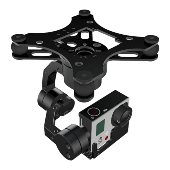
X-CAM A10-3H 3 Axis Gimbal for GOPRO
User Manual
The X-CAM A10-3H 3 Axis Gimbal has been setup and calibrated for use
with GOPRO cameras, it is ready to use straight from the box.
Specifications:
Weight: 280g ( without GOPRO )
Stabilization Frequency: 5200Hz
Input Voltage (DC IN): 7.4v ~ 22.2v ( 2S ~ 6S Lipo )
Tilt Travel: +-90 degrees; Rolling Travel: +-45 degrees
Pan Travel: 360 degrees with unlimited rotation
Built-in AV output & Camera Charging
Auto Pilot System support is not required
Built-in 2 X 6 Axis gyroscope sensors & 1 Infrared localizer.
Supports automatic back to HOME function.
Supports GoPro3,GoPro3+,GoPro4(black or silver version)
●
1 x X-CAM A10-3H Gimbal Frame
●
1 x X-CAM A10-3H Controller
●
1 x USB Cable
●
1 x PPM Cable
●
5 x Damping balls
●
4 x Rubber rings
●
4 x Fastener rings.
( V2.00 )
The S-BUS input is required for full functionality. The channels
are:
Channel 1: ROLL
Channel 2: Return to HOME
Channel 3: TILT
Channel 4: PAN
Channel 5: Mode Switch
The recommend operation methods:
1. Single control: Just connect a PPM channel for PAN control
or HEAD FOLLOWING , HEAD LOCK and AUTO BACK TO
HOME mode(Default), S-BUS connection is not required,
One receiver only.
2. Dual control: Only S-BUS input mode provides full
functionality, 2 receivers are required.
Advertisement
Table of Contents

Related Manuals for X-cam A10-3H

Summary of Contents for X-cam A10-3H
- Page 1 2 receivers are required. Notice: You do not have to provide power to the S-BUS Receiver. The A10-3H Controller provides a 5V supply via the S-BUS input. The TILT and Pan axis (or Mode Switch) can be controlled under the single control or dual control.
- Page 2 AV output adapter instruction You can either use a 3.5mm Stereo audio connector, or you can connect your own video transmitter using the wire circled in red. The YELLOW wire is the video signal and the PINK wire is GND. PC Software Connect with PC.
- Page 3 Acc. Gain: After adjusting the Pos. Gain, Inclined the gimbal to one position quickly and watch the video image is horizontal in time, if not please adjust the Acc. Gain in the software . Notice: the X-CAM A10-3H has been finished the adjusting, does not need to adjust again in normally Gimbal Control The A10-3H provides 2 ways to control TILT, Linear Mode or Tracking Mode Linear Mode: TILT changes when the control stick is moved from the center position.
- Page 4 This is an advanced setup, normally it does not need to set unless serious tilt has happened on the Tilt or Roll axis .For more details please read the X-CAM A10-3H initial data reset guide appendix 1. Function choosing on single control...
- Page 5 Make sure the center of gravity of the X-CAM A10-3H is correct before using. It is not required to supply power to the second receiver when under dual control mode. The A10-3H will supply power over S-BUS The X-CAM A10-3H supports S-BUS1 only.
- Page 6 (Picture 3) ( 3 ) After the calibration ,click the button of “Disconnect ”,and power off the X-CAM A10-3H . Then re-power the X-CAM A10-3H to check if the bubble is at the center position or not. (Absolute center position is not required.)
- Page 7 3. Load the “A10-3H 20141022 V2.18A Bate.Bin” firmware to the X-CAM A10-3H and close the firmware upgrade program, and power off the X-CAM A10-3H. 4. Power on the X-CAM A10-3H and observe the gimbal’s behavior, if it is unordered turning try the step 1 and step 2 again. (Step 2 must be executed).
Need help?
Do you have a question about the A10-3H and is the answer not in the manual?
Questions and answers