Avigilon ENC-4P-H264 Installation Manual
Analog video encoder
Hide thumbs
Also See for ENC-4P-H264:
- Installation manual (19 pages) ,
- User manual (192 pages) ,
- Web interface user manual (35 pages)

Subscribe to Our Youtube Channel
Related Manuals for Avigilon ENC-4P-H264


Summary of Contents for Avigilon ENC-4P-H264
-
Page 1: Installation Guide
Installation Guide Avigilon Analog Video Encoder Model: ENC-4P-H264 920-0044B-Rev2... -
Page 3: Important Safety Information
Source” with output rated 12 VDC or 24 VAC, 8 W min. or Power over Ethernet (PoE), rated 48 VDC, 8 W min. • Any external power supply connected to this product may only be connected to another Avigilon product of the same... - Page 4 • Do not use strong or abrasive detergents when cleaning the device body. • Use only accessories recommended by Avigilon. • Use of controls or adjustments or performance of procedures other than those specified in this document may result in hazardous radiation exposure.
-
Page 5: Regulatory Notices
Changes or modifications made to this equipment not expressly approved by Avigilon Corporation or parties authorized by Avigilon Corporation could void the user’s authority to operate this equipment. Disposal and Recycling Information... - Page 6 The contents of this manual and the specifications of this product are subject to change without notice. Avigilon reserves the right to make changes without notice in the specifications and materials contained herein and shall not be...
-
Page 7: Table Of Contents
Table of Contents Overview ......1 Front View ....... . 1 Rear View . -
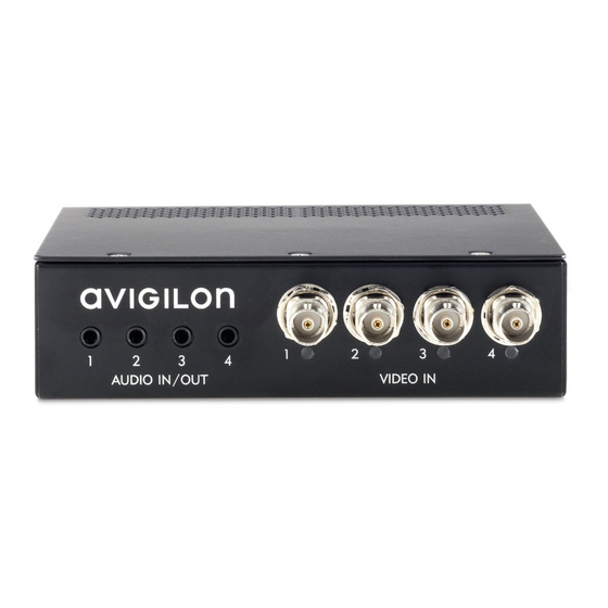
Page 9: Overview
Overview Front View Video Inputs Audio Inputs/ Outputs Video Input Status LEDs Feature Description Video Inputs Four BNC inputs for connecting analog video devices. Video Input Provides information about the status of the analog Status LEDs video signal. The LED turns on when a video signal has been detected. -
Page 10: Rear View
Rear View Connection I/O Terminals Status LED Ethernet Port Power Connector Block Feature Description Connection Provides information about device operation. See Status LED LED indicators for more information. Ethernet Port Accepts an Ethernet connection to a network. Server communication and image data transmission occurs over this connection. -
Page 11: Installation
— for connecting power when not using Power over Ethernet. Package Contents Ensure the package contains the following: • Avigilon H.264 Video Encoder • Terminal Block Installation Steps Complete the following procedures to install the encoder. Mounting the Encoder on page 3... -
Page 12: Connecting Cables
The encoder can be attached to the bracket by lining up the four holes on the bottom of the encoder with the hole pattern on the bracket and screwing them together with the screws provided with the bracket. Warning — •... -
Page 13: Assigning An Ip Address
Zeroconf, the IP address is in the 169.254.0.0/16 subnet. The IP address settings can be changed using one of the following methods: • (Recommended) Avigilon Camera Installation Tool software application. • Encoder's web browser interface: http://<encoder IP address>/... -
Page 14: Accessing The Live Video Stream
Additional information about setting up and using the device is available in the following guides: • Avigilon Camera Installation Tool User Guide • Avigilon Control Center Client User Guide • Avigilon High Definition H.264 Web Interface User Guide The manuals are available on the Avigilon website: http://avigilon.com/ #/support-and-downloads. -
Page 15: Cable Connections
Cable Connections Connecting External Power NOTE: Do not perform this procedure if Power over Ethernet (POE) is used. If PoE is not available, the encoder needs to be powered through the removable power connector block. Refer to the diagrams in this guide for the location of the power connector block. -
Page 16: Connecting To External Devices
Connecting to External Devices External devices are connected to the encoder through the I/O terminal. The pinout for the I/O terminal is shown in the following table and diagram. Table:External I/O Terminals Function Description 3.3 VDC 3.3 VDC output. May be used to power small @200 mA max relays in conjunction with the relay outputs. -
Page 17: Connecting Microphones And Speakers
Connecting Microphones and Speakers The encoder can be connected to up to four external microphones and speakers through the audio connectors. The audio connectors support input and output for line-level audio signals. The connector is a mini- jack (3.5mm). The pinout is shown in the following diagram. Audio input and output use the left and right audio connections normally used on a stereo audio device. -
Page 18: Led Indicators
LED Indicators Once the encoder is connected to the network, the Connection Status LED will display the encoder’s progress in connecting to the Network Video Management software. The following table describes what the LEDs indicate: Table:LED Indicators Connection Connection Description State Status LED Obtaining IP... -
Page 19: Reset To Factory Default Settings
Reset to Factory Default Settings If the encoder no longer functions as expected, you can choose to restore the encoder to its factory default settings. Use the firmware revert button to reset the encoder. Firmware Revert Button Figure: Firmware revert microswitch location on the rear of the encoder Disconnect power from the encoder. -
Page 20: Setting The Ip Address Through The Arp/Ping
Setting the IP Address Through the ARP/Ping Method Complete the following steps to configure the encoder to use a specific IP address: Locate and copy down the MAC Address (MAC) listed on the Serial Number Tag for reference. Open a Command Prompt window and enter the following commands: arp -s <New Encoder IP Address>... -
Page 21: Specifications
Specifications Encoder Video Input BNC connector Audio Input/Output Line-level signal, TRS mini-jack (3.5 mm) Network Network 100Base-TX Cabling Type CAT5 Connector RJ-45 ONVIF compliant (www.onvif.org) Security Password protection, HTTPS encryption, digest authentication, WS authentication, user access log Protocols IPv4, HTTP, HTTPS, SOAP, DNS, NTP, RTSP, RTCP, RTP, TCP, UDP, IGMP, ICMP, DHCP, Zeroconf, ARP Streaming Protocols RTP/UDP, RTP/UDP multicast, RTP/RTSP/TCP, RTP/RTSP/HTTP/TCP,RTP/... -
Page 22: Limited Warranty & Technical Support
Limited Warranty & Technical Support Avigilon warrants to the original consumer purchaser, that this product will be free of defects in material and workmanship for a period of 3 years from date of purchase. The manufacturer’s liability hereunder is limited to replacement of the product, repair of the product or replacement of the product with repaired product at the discretion of the manufacturer.
Need help?
Do you have a question about the ENC-4P-H264 and is the answer not in the manual?
Questions and answers