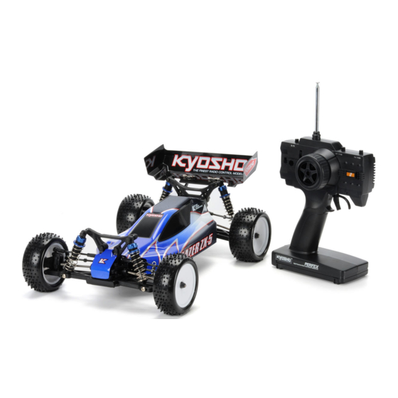
Kyosho Lazer ZX-5 Instruction Manual
1:10 scale radio controlled electric powered 4wd racing buggy
Hide thumbs
Also See for Lazer ZX-5:
- Instruction sheet (6 pages) ,
- Instrution manual (24 pages) ,
- Instruction manual (33 pages)
Table of Contents
Advertisement
Before beginning assembly, please read these instructions thoroughly!
THE FINEST RADIO CONTROL MODELS
INSTRUCTION MANUAL
1:10 Scale Radio Controlled Electric Powered 4WD Racing Buggy
LAZER ZX - 5
INDEX
ASSEMBLY
Spare Parts & OPTIONAL PARTS
The product you have purchased is powered by a rechargeable battery. The battery is recyclable. At the end of its useful life, under various national /
state and local laws, it may be illegal to dispose of this battery into the municipal waste stream. Check with your local solid waste officials for details
Ni-Cd Ni-MH
in your area for recycling options or proper disposal.
© 2005 KYOSHO CORPORATION
30076-T01
R
*SPECIFICATIONS ARE SUBJECT TO CHANGE WITHOUT NOTICE.
UNDER SAFETY PRECAUTIONS
This radio control model is not a toy!
First-time builders should seek the advice of experienced modelers before
beginning assembly and if they do not fully understand any part of the
construction.
Assemble this kit only in places out of childrenÕs reach!
Take enough safety precautions prior to operating this model. You are responsible
for this modelÕs assembly and safe operation!
Always keep this instruction manual ready at hand for quick reference, even after
completing the assembly.
2~3
4~5
5~26
27~29
30~31
32~33
No. 30076
Advertisement
Table of Contents

Related Manuals for Kyosho Lazer ZX-5


Summary of Contents for Kyosho Lazer ZX-5
-
Page 1: Instruction Manual
Check with your local solid waste officials for details Ni-Cd Ni-MH in your area for recycling options or proper disposal. *SPECIFICATIONS ARE SUBJECT TO CHANGE WITHOUT NOTICE. No. 30076 © 2005 KYOSHO CORPORATION 30076-T01... - Page 2 This kit does not supply tires and inner Sponge. Use tires and Inner Sponge for (Recommended: 10T) 1/10 buggies. Paint and Brush No.76301 76711 KYOSHO SPRAY COLOR For painting the body, use Kyosho paints for models! No.2230 PAINT BRUSH CAUTION: Before POLYCA COLOR using spray colors,...
- Page 3 Phillips Screwdriver ( L. M. S. ) Needle Nose Pliers Grease No.96154 Wire Cutters Rubber Cement KYOSHO Sharp Hobby Knife KYOSHO Special Glue Instant Glue TOOLS INCLUDED Ball Differential Grease Hex Wrench No.1829 No.695101 KNIFE EDGE REAMER ROUND CUTTER & SANDER...
- Page 4 Read through the manual before you begin, so you will have an overall idea of what to do. Check all parts. If you find any defective or missing parts, contact your local dealer or our Kyosho Distributor. How to read the instruction manual: No.4, No.5, No.6...
- Page 5 BEFORE YOU BEGIN (2) This kit contains screws and hardware in different metric sizes and shapes. Before using them, check the screws on the true-to-scale diagrams on the left side in each assembly step. Some screws are extras. SCREWS OTHER HARDWARE Screw Self-tapping (TP) Screw Screw...
- Page 6 ARRANGEMENT OF PLASTIC PARTS ON RUNNERS (2) Shaded Parts are not used. 123 123 122 122 122 122 123 123 73 73...
- Page 7 No.1 Ball Differential Compress with pliers. Ball Differential Grease Face the rounded side to balls. When installing in gearbox, change to from the opposite side if the backlash is too loose. Ball Differential Grease Molybdenum Grease Remove flashing. 17 10 x 15 x 4mm 10 x 12 x 0.1mm 2.6 x 25mm 2.6 x 6 x 1mm...
- Page 8 No.1, No.2 Front If using front one-way bearing specifications. Marked side. 2x4mm Insert until flush. Unmarked side. 2x4mm 2 x 4mm 10 x 12 x 0.1mm Screw Shim 10 x 15 x 4mm Ball Bearing 10 x 12 x 0.2mm Shim If using rigid on front.
- Page 9 No.1 Main Gear & tight with no play. Remove flashing. Insert straight. 1.5 x 8.8mm 5 x 7 x 0.3mm Washer 29 5 x 10 x 4mm Ball Bearing E-ring No.1 Main Gear Flanged Nylon Nut Align the & grooves. Prevent them from becoming sandwiched.
- Page 10 3 x 6mm 17 10 x 15 x 4mm No.2, No.3 Rear Gearbox F/H Screw Ball Bearing 3 x 8mm F/H Screw Use in 3 x 8mm 3x8mm Screw Cut off. 3x6mm For Rear 3x8mm < > < Reverse > Remove 3x8mm flashing.
- Page 11 3 x 22mm 3 x 8mm No.2 Rear Shock Stay Cap Screw Screw 3 x 10mm Screw 3x22mm 3x8mm 3x10mm 3x8mm 3x10mm 3x22mm Use this hole. No.3, No.4 Rear Suspension 5 x 10 x 4mm Ball Bearing 5 x 7 x 0.3mm Washer 97 4.8mm Ball Stud (L)
- Page 12 No.2, No.4 Rear Suspension 2.6 x 4mm Screw 3 x 8mm F/H Screw 3x8mm 147 3 x 5 x 0.2mm 3x8mm Washer 134 3 x 27mm Shaft 135 3 x 44mm Shaft 132 3 x 6 x 2mm Collar 2.6x4mm Rear Suspension No.3, No.4 Projection.
- Page 13 No.3, No.4 Rear Stabilizer < > < > < for Left > < for Right > 100 4.8mm Ball End (Short) 3 x 10mm Set Screw 3x10mm 3 x 6mm Screw 3x6mm 3 x 3mm Set Screw 3x3mm 3x3mm No.5 <...
- Page 14 No.5 Shock Absorber Keep expanded. Non-Pressure Type Insert the shaft slowly. Tighten the cap Put the oil. for Front (Short) firmly,and pull the shaft. Tighten the cap until for Rear (Long) it slightly stops, then loosen it for a 1/2nd lap. O-ring (Large) Surplus oil comes out.
- Page 15 No.3 Servo Saver 116 4.8mm Ball Stud (S) 28 5 x 8 x 2.5mm Ball Bearing 1.5mm No.2, No.3, No.4 Servo Saver 2.6mm 2.6mm 2.6mm Nylon Nut 3 x 5 x 0.2mm Washer 2.6mm Washer Remove flashing. 3 x 6mm F/H Screw 3x6mm 3x6mm...
- Page 16 No.2, No.3 Servo Saver 97 4.8mm Ball Stud (L) 122 3 x 6 x 1mm Collar Front Narrow Wide No.1, No.2 Front Differential 1.5 x 8.8mm E-ring 23 2 x 7.8mm O-ring P8 5 x 7 x 0.3mm Washer 5 x 10 x 4mm Ball Bearing Part bags used.
- Page 17 No.2 Front Differential < > < > < > < > For differential specifications For front one-way specifications Unmarked side. Spot glue. Sponge Cap O-ring 3 x 8mm No.2 Front Gearbox F/H Screw 3 x 8mm Screw 116 4.8mm Ball Stud (S) For Front "C"...
- Page 18 No.2 Front Shock Stay 3x22mm 3 x 22mm Cap Screw 3x8mm 3x8mm 3 x 8mm Screw 3x22mm No.2 3x15mm Front Gearbox 3x15mm 3x8mm 3 x 8mm Screw 3 x 15mm Screw Part bags used.
- Page 19 No.2 Steering Servo In case of the following sizes, use Cut away shaded area if 10mm contact with center shaft. Shorter than 10mm. 3x12mm 28mm Longer than 28mm. FUTABA , KO, JR Steering Servo SANWA, KO, JR HITEC 3x8mm Adjustment depends on servo. 3x8mm 90û...
- Page 20 No.2, No.4 Front Suspension 3 x 10mm Screw 3 x 12mm Screw 147 3 x 5 x 0.2mm Washer 135 3 x 44mm Shaft 3x10mm 3x12mm 3x12mm "D" Inscription. No.3, No.4 Front Suspension for Right for Left Long Short 5 x 7 x 0.3mm Washer for Left 116 4.8mm...
- Page 21 No.2, No.4 Use only with front one-way specifications. Front Suspension 3 x 6mm F/H Screw 2.6 x 4mm Screw 3 x 3mm Set Screw 133 3 x 25mm Shaft 2.6x4mm Sponge Cap 3x6mm 3x3mm 3x6mm No.3, No.4 Steering Tie Rod Front Suspension <...
- Page 22 Front Suspension Projection. Note direction. Long Projection. Note direction. Short (For Left) No.5 Front Suspension 169 5.8mm Ball 3 x 12mm Screw 3x12mm Part bags used. Pay close attention here! Assemble left and right sides the same way.
- Page 23 No.1, No.2 3x3mm Center Shaft 3 x 3mm Set Screw Put the front end of into the cup, then move into place. Front 3x12mm No.2 3x10mm Upper Deck 3x8mm 3 x 8mm Screw 3 x 10mm Unscrew the screws temporarily tightened, Screw and attach with them.
- Page 24 Radio Connect as per radio Antenna Pipe Antenna instruction manual. Electronic Speed Controller Receiver Double-sided Tape 3 x 10mm 3 x 3mm No.2 Motor Screw Set Screw 3 x 8 x 0.5mm O-ring Washer 3x10mm Tighten the screws with one sheet of 3x10mm paper inserted between both gears.
- Page 25 Battery < > < > Note the direction. If using battery packs Battery 3 x 10mm F/H Screw 3x8mm(F/H) Hook Pin 3x8mm(F/H) < > < > If using loose battery cells Side with larger hole faces sponge. Batteries can be moved to forward and rear positions. Side with larger hole faces sponge.
- Page 26 Body Shell Body Mounting Hook Pin 0 deg (7 deg) +3 deg (10 deg) -3 deg (4 deg) Remove when adjust. Cut off shaded portion. Drill holes with the Must be purchased separately! Assemble left and right specified diameter. sides the same way.
- Page 27 OPERATING YOUR MODEL SAFELY WARNING: Do NOT operate the model in the following places and situations: (Non-observance may lead to accidents!) Always check the dry batteries in the radio! When the dry batteries get weaker, transmission and reception of the radio decrease. You may lose control of your model when operating it under such condition.
- Page 28 / PROPER OPERATING PROCEDURES Fully charge the Ni-Cd battery. Check the transmitter batteries. Make sure the throttle control is in neutral. CH-2 CH-1 CH-2 CH-1 BATT. BATT. Connect the Ni-Cd battery. Extend the transmitter antenna. Switch on the transmitter. CH-2 CH-1 BATT.
- Page 29 TROUBLESHOOTING PROBLEM CAUSE REMEDY Steering control servo does not Transmitter and/or receiver is not switched on. Switch on. operate. Transmitter batteries are weak. Replace with new batteries. Improper radio installation. Correct as per radio instruction manual. Motor does not run. Ni-Cd battery capacity is insufficient.
- Page 30 LA220 LA213 LA214 XXXXX BRG001 LA231 LA213 96641 XXXXX 96643 SP107H SP107H W5028W LA213 LA230 BRG001 BRG001 LA219-7 W5026W LA213 LA218 BRG001 LA230 LA220 96641 LA219-7 LA218 LA220 LA220 LA228 96641 LA213 UM310 LA229 LAZER ZX-5 © 2005 KYOSHO CORPORATION...
- Page 31 1890 177 x 10 92638 Body (LAZER ZX-5) Snap Pin LAZER ZX-5 1x100x150 LAD01 186 x 1 96441B Decal Set (LAZER ZX-5) Sponge Tape (1x100x150) LA240 181 x 1 LA22 95 96 x 2 Sagittarius Wing (Hl-Df) Steering Pin 05.09...
- Page 32 SPARE PARTS FOR JAPANESE MARKET ONLY. Part Names Quantity Part Names Quantity VZW010-1 21 23 x 2 92635 King Pin (Steel) 141 x 2 O-ring ¥ Shaft Set & 29 x 4 BRG001 1050 92921 Ball Bearing 5x10mm Servo Saver Tube & Spring BRG002 28 x 4 1050...
- Page 33 THE FINEST RADIO CONTROL MODELS http://www.kyosho.com 243-0034 046-229-4115 )10 00 18 00 PRINTED IN JAPAN 61920509-1 05.09...
Need help?
Do you have a question about the Lazer ZX-5 and is the answer not in the manual?
Questions and answers