Table of Contents
Advertisement
Notes: This model's CD mechanism changer unit is CR14C. Please refer to the original Service Manual
(Order No. MD0805031CE) for this mechanism.
Specifications
AMPLIFIER SECTION
RMS output power
Front Ch (both channels driven)
250 W per channel (6 Ω), 1 kHz, 10% THD
Subwoofer Ch
200 W per channel (6 Ω), 100 Hz, 10% THD
Total RMS stereo mode power
PMPO
FM/AM TUNER, TERMINALS SECTION
Preset station
Frequency Modulation (FM)
Frequency range
87.9 to 107.9 MHz (200 kHz steps) (PL only)
87.5 to 108.00 MHz (100 kHz steps) (PL only)
87.50 to 108.00 MHz (50 kHz steps) (GCP only)
Antenna terminal(s)
Amplitude Modulation (AM)
Frequency range
520 to 1710kHz (10 kHz steps) (PL only)
522 to 1629 kHz (9 kHz step) (GCP only)
522 to 1630 kHz (10 kHz steps) (GCP only)
Music Port (front) jack
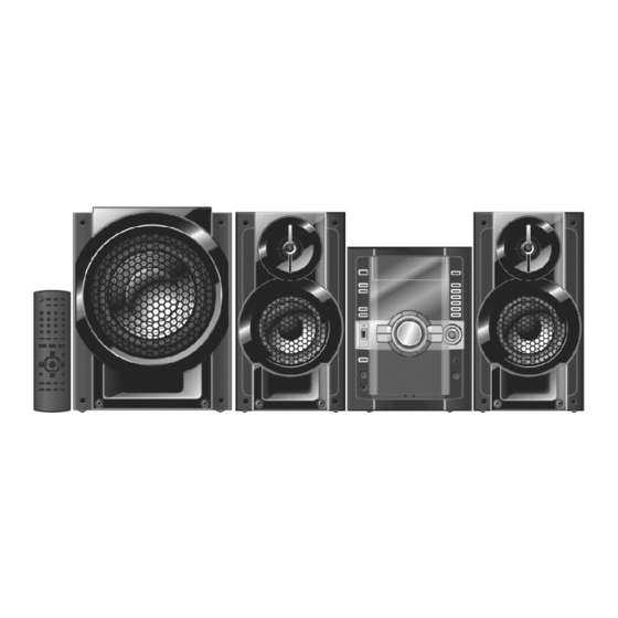
SA-AK770PL
SA-AK770GCP
Colour
(K)... Black Type
Sensitivity
Terminal
Headphone jack
Terminal
Output level (CD, 1 kHz, -20 dB)
Mic jack
700 W
Sensitivity
7700 W
Terminal
FM 30 stations
Type
AM 15 stations
Track system
Heads
Record/playback
Erasure
Motor
Recording system
75 Ω (unbalanced)
Erase system
Tape speed
Overall frequency response (+3, -6 dB) at DECK OUT
NORMAL
S/N ratio
Wow and flutter
Fast forward and rewind time
ORDER NO. MD0805007CE
CD Stereo System
Mono, 3.5 mm jack (1 system)
Double gap ferrite head
© 2008 Matsushita Electric Industrial Co. Ltd.. All
rights
reserved.
Unauthorized
distribution is a violation of law.
100 mV, 4.0 k Ω
Stereo, 3.5 mm jack
Stereo, 3.5 mm jack
32 Ω (Max)
0.7 mV, 1.2 k Ω
1 way
4 track, 2 channel
Solid permalloy head
DC servo motor
AC bias 100 kHz
AC erase 100 kHz
4.8 cm/s
35 Hz to 10 kHz
50 dB (A weighted)
0.18 % (WRMS)
copying
and
Advertisement
Table of Contents

Related Manuals for Panasonic SA-AK770PL


Summary of Contents for Panasonic SA-AK770PL
-
Page 1: Specifications
ORDER NO. MD0805007CE CD Stereo System SA-AK770PL SA-AK770GCP Colour (K)... Black Type Notes: This model’s CD mechanism changer unit is CR14C. Please refer to the original Service Manual (Order No. MD0805031CE) for this mechanism. Specifications 100 mV, 4.0 k Ω... -
Page 2: Table Of Contents
SA-AK770PL / SA-AK770GCP Approx. 120 seconds with C-60 cassette tape USB recording speed 1x, max 4x (CD only) DISC SECTION GENERAL Disc played [8 cm or 12 cm] Power supply (1) CD-Audio (CD-DA) AC 120 V, 60Hz (PL only) (2) CD-R/RW (CD-DA, MP3* formatted disc) -
Page 3: Safety Precautions
SA-AK770PL / SA-AK770GCP 1 Safety Precautions 1.1. General Guidelines 1. When servicing, observe the original lead dress. If a short circuit is found, replace all parts which have been overheated or damaged by the short circuit. 2. After servicing, ensure that all the protective devices such as insulation barriers and insulation papers shields are properly installed. -
Page 4: Before Repair And Adjustment
SA-AK770PL / SA-AK770GCP 1.3. Before repair and adjustment Disconnect AC power, discharge AC Capacitors C5700, C5701, C5703, C5704, C5705 (PL Only); C5700, C5701, C5703, C5704, C5705, C5706 & C5707 (GCP Only) through a 10Ω, 5W resistor to ground. DO NOT SHORT-CIRCUIT DIRECTLY (with a screwdriver blade, for instance), as this may destroy solid state devices. -
Page 5: Prevention Of Electro Static Discharge (Esd) To
SA-AK770PL / SA-AK770GCP Reference No. Part No. Part name & Description Remarks T5701 ETS48AB116AC SWITCHING TRANSFORMER [M] GCP T5701 ETS48AB12GAC SWITCHING TRANSFORMER [M] PL T5751 ETS19AB256AG BACKUP SW TRANFORMER PC5701 B3PBA0000402 PHOTO COUPLER PC5702 B3PBA0000402 PHOTO COUPLER PC5720 B3PBA0000402 PHOTO COUPLER... -
Page 6: Handling Precautions For Traverse Unit
SA-AK770PL / SA-AK770GCP 3 Handling Precautions for Traverse Unit The laser diode in the optical pickup unit may break down due to static electricity of clothes or human body. Special care must be taken avoid caution to electrostatic breakdown when servicing and handling the laser diode in the traverse unit. - Page 7 SA-AK770PL / SA-AK770GCP...
-
Page 8: Precaution Of Laser Diode
SA-AK770PL / SA-AK770GCP 4 Precaution of Laser Diode CAUTION : This product utilizes a laser diode with the unit turned "on", invisible laser radiation is emitted from the pickup lens. Wavelength: 785 nm (CD) / 655 nm (DVD) Maximum output radiation power from pickup: 100 µW/VDE Laser radiation from the pickup unit is safety level, but be sure the followings: 1. -
Page 9: Service Caution Based On Legal Restrictions
SA-AK770PL / SA-AK770GCP 5 About Lead Free Solder (PbF) 5.1. Service caution based on legal restrictions 5.1.1. General description about Lead Free Solder (PbF) The lead free solder has been used in the mounting process of all electrical components on the printed circuit boards used for this equipment in considering the globally environmental conservation. -
Page 10: Operation Procedures
SA-AK770PL / SA-AK770GCP 6 Operation Procedures 6.1. Main Unit Key Buttons Operations... -
Page 11: Remote Control Key Buttons Operations
SA-AK770PL / SA-AK770GCP 6.2. Remote Control Key Buttons Operations... -
Page 12: Using The Music Port
SA-AK770PL / SA-AK770GCP 6.3. Using the Music Port This feature enables you to enjoy music from a portable audio equipment. - Page 13 SA-AK770PL / SA-AK770GCP 6.4. Connecting and Playing a USB Mass Storage Class Device...
-
Page 14: Self Diagnosis And Special Mode Setting
SA-AK770PL / SA-AK770GCP 7 Self diagnosis and special mode setting This unit is equipped with features of self-diagnostic & special mode setting for checking the functions & reliability. Special Note : Checking of the reliability (ageing) & changer operation must be carry out to ensure good working condition in unit. - Page 15 SA-AK770PL / SA-AK770GCP 7.2.2. Service Mode Table 2 Item FL Display Key Operation Mode Name Description Front Key FL Display Test To check the FL In doctor mode: segments display (All 1. Press [1] button on remote control. segments will light up)
- Page 16 SA-AK770PL / SA-AK770GCP Item FL Display Key Operation Mode Name Description Front Key CD-MP3 Reading To check for the CD-MP3 In doctor mode: & Playing Reading setting of the 1. Press [5] button on remote control. inspection main unit. The volume...
- Page 17 SA-AK770PL / SA-AK770GCP Item FL Display Key Operation Mode Name Description Front Key Cold Start (Reset) To activate cold start In service mode: ipon next AC power up. 1. Press [3] button on remote control. To exit Service Mode, press [ ] button on main unit or remote control.
- Page 18 SA-AK770PL / SA-AK770GCP...
-
Page 19: Error Code Table Display
SA-AK770PL / SA-AK770GCP 7.4. Error code Table Display Self-Diagnosis Function (refer Section “7.2.1 Service Mode Table 1”) provides information on any problems occuring for the unit and its respective components by displaying the error codes. These error code such as U**, H** and F** are stored in memory and held unless it is cleared. - Page 20 SA-AK770PL / SA-AK770GCP 7.4.1. Error Code Table (For Deck Mechanism) Error Code Diagnosis Contents Description of error Automatic FL Display Remarks Mode SW, plunger Normal operation during For deck mechanism unit. and capstan motor mecha transition, MODE Press [ ] on main unit for...
-
Page 21: Power Supply
SA-AK770PL / SA-AK770GCP Error Code Diagnosis Contents Description of error Automatic FL Display Remarks MODEH Mode change to mode change For CD Mechanism unit (CR14C). horizontal operation horizontal operation cannot Press [EXCHANGE] on main unit for faulty complete when time out next error. -
Page 22: Assembling And Disassembling
SA-AK770PL / SA-AK770GCP 8 Assembling and Disassembling 8.1. Caution Special Note: This model uses a new Mechanism unit (CR14C). In this following section does not contain the necessary disassembly & assembly information for the Mechanism unit (CR14C) except the disassembly & assembly of traverse unit. Kindly refer to the original service manual for the Mechanism unit. - Page 23 SA-AK770PL / SA-AK770GCP • Replacement for Switch Regulator Diode (D5702) • Replacement for Regulator Diode (D5801) • Replacement for Regulator Diode (D5802) • Replacement for Regulator Diode (D5803) • Disassembly of AC Inlet P.C.B. • Disassembly of Voltage Selector P.C.B. (For GCP Only)
-
Page 24: Disassembly Flow Chart
SA-AK770PL / SA-AK770GCP 8.2. Disassembly flow chart The following chart is the procedure for disassembling the casing and inside parts for internal inspection when carrying out the servicing. To assemble the unit, reverse the steps shown in the chart as below. - Page 25 SA-AK770PL / SA-AK770GCP 8.3. Main Components and P.C.B. Location...
-
Page 26: Disassembly Of Top Cabinet
SA-AK770PL / SA-AK770GCP catches. 8.4. Disassembly of Top Cabinet Step 1 Remove 3 screws on both sides of Top Cabinet. Step 5 Lift up the Top Cabinet and remove it in the direction of Step 2 Remove 5 screws at the rear panel. - Page 27 SA-AK770PL / SA-AK770GCP Step 2 Detach 22P FFC cable at connector (CN2801) at Main P.C.B.. Step 3 Detach 11P FFC cable at connector (CN2802) at Main Special Note: During reassembling procedure, ensure both the P.C.B.. claws and catches are fully catched.
- Page 28 SA-AK770PL / SA-AK770GCP Notes: 1. For disassembly & assembly of traverse unit, please refer to Step 11 Release mechanism unit from the 2 locators. original Service Manual for the Disassembly and Assembly of the Mechanism Unit (CR14C). Step 12 Lift up the Mechanism Unit (CR14C).
-
Page 29: Disassembly Of Fan Unit
SA-AK770PL / SA-AK770GCP Step 5 Desolder 4 points. Step 6 Remove Jupiter USB P.C.B.. Step 3 Remove 1 screw at the rear panel. Note : During reassembling procedures, ensure 4 points is solder onto Jupiter USB P.C.B.. 8.7. Disassembly of Fan Unit •... -
Page 30: Disassembly Of Rear Panel
SA-AK770PL / SA-AK770GCP Note: During reassembling procedures, ensure wires are properly dressed in the hook. Step 2 Slide the Voltage Seclector P.C.B. as arrow shown. Step 3 Slightly lift up the Mechanism Unit (CR14C) from the 2 locators. Step 4 Release 2 catch from the side panel. -
Page 31: Disassembly Of Front Panel Unit
SA-AK770PL / SA-AK770GCP Step 7 Detach the front panel unit. 8.9. Disassembly of Front Panel Unit • Follow the (Step 1) - (Step 5) of Item 8.4 • Follow the (Step 7) - (Step 10) of Item 8.5 Step 1 Detach 27P FFC cable at connector (CN2806) at Main P.C.B.. - Page 32 SA-AK770PL / SA-AK770GCP Step 2 Remove 9 screws at Panel P.C.B.. Step 5 Release 6 catches at Tact Switch P.C.B.. Step 3 Remove 2 screws at Tact Switch P.C.B.. Step 4 Release 2 catches at Panel P.C.B.. Step 6 Release 2 catches at Remote Sensor P.C.B..
- Page 33 SA-AK770PL / SA-AK770GCP • Disassembly of Side Bar (L) Led P.C.B. Step 9 Detach 4P connector (CN6604) at Side Bar (L) Led P.C.B. at Panel P.C.B.. • Disassembly of Side Bar (R) Led P.C.B. Step 10 Detach 4P connector (CN6602) at Side Bar (R) Led P.C.B.
- Page 34 SA-AK770PL / SA-AK770GCP 8.11. Disassembly of Mic P.C.B. • Follow the (Step 1) - (Step 5) of Item 8.4 • Follow the (Step 7) - (Step 10) of Item 8.5 • Follow the (Step 1) - (Step 7) of Item 8.9 Step 1 Remove Mic knob as arrow shown.
-
Page 35: Disassembly Of Cd Lid
SA-AK770PL / SA-AK770GCP 8.14. Disassembly of CD Lid • Follow the (Step 1) - (Step 5) of Item 8.4 • Follow the (Step 7) - (Step 10) of Item 8.5 • Follow the (Step 1) - (Step 7) of Item 8.9 Step 1 Remove the spring as arrow shown in order of sequences (1) to (3). - Page 36 SA-AK770PL / SA-AK770GCP 8.16. Disassembly of Deck P.C.B. • Follow the (Step 1) - (Step 5) of Item 8.4 • Follow the (Step 7) - (Step 10) of Item 8.5 • Follow the (Step 1) - (Step 7) of Item 8.9 •...
- Page 37 SA-AK770PL / SA-AK770GCP Step 3 Remove 2 screws at the Deck Mechanism unit. Step 4 Remove head block. 8.17. Disassembly of Deck Mechanism • Follow the (Step 1) - (Step 5) of Item 8.4 • Follow the (Step 7) - (Step 10) of Item 8.5 •...
- Page 38 SA-AK770PL / SA-AK770GCP...
-
Page 39: Disassembly Of Cassette Lid
SA-AK770PL / SA-AK770GCP 8.19. Disassembly of Cassette Lid • Follow the (Step 1) - (Step 5) of Item 8.4 8.18. Disassembly of Deck • Follow the (Step 7) - (Step 10) of Item 8.5 Mechanism P.C.B. • Follow the (Step 1) - (Step 7) of Item 8.9 •... -
Page 40: Disassembly Of Traverse Unit
SA-AK770PL / SA-AK770GCP Step 2 Desolder 4 solder points. Step 2 Push the lever upward and open the cassette lid. Step 3 Remove 3 screws. Note: Follow Disassembly of Cassette Lid to remove the cassette tape. 8.21. Disassembly of Traverse Unit Step 4 Flip over the CD Servo P.C.B.. - Page 41 SA-AK770PL / SA-AK770GCP 8.22. Disassembly of D-Amp P.C.B. • Follow the (Step 1) - (Step 5) of Item 8.4 • Follow the (Step 1) - (Step 12) of Item 8.5 Step 1 Detach 17P FFC cable at connector (CN5050) at D- Amp P.C.B..
- Page 42 SA-AK770PL / SA-AK770GCP Step 5 Remove 4 screws at the rear panel. Step 7 Remove 3 screws from D-Amp P.C.B.. Step 8 Lift up D-Amp P.C.B. as arrow shown. Step 6 Lift up the D-Amp P.C.B. together with the chassis support as arrow shown.
-
Page 43: Replacement Of Audio Digital
SA-AK770PL / SA-AK770GCP support. 8.23. Replacement of Audio Digital Amp IC (IC5400) • Follow the (Step 1) - (Step 5) of Item 8.4 • Follow the (Step 1) - (Step 12) of Item 8.5 • Follow the (Step 1) - (Step 8) of Item 8.22 Step 1 Flip over D-Amp P.C.B.. - Page 44 SA-AK770PL / SA-AK770GCP 8.24. Replacement of Audio Digital Step 4 Remove TR Spring in the direction of arrow shown. Amp IC (IC5000) Step 5 Remove Audio Digital Amp IC (IC5000) from the heat sink unit A. • Follow the (Step 1) - (Step 5) of Item 8.4 Caution: Handle the heat sink Unit A power unit with •...
- Page 45 SA-AK770PL / SA-AK770GCP Step 4 Remove TR Spring in the direction of arrow shown. 8.25. Replacement of Audio Digital Step 5 Remove Audio Digital Amp IC (IC5200) from the heat Amp IC (IC5200) sink unit A. Caution: Handle the heat sink Unit A power unit with •...
- Page 46 SA-AK770PL / SA-AK770GCP Step 7 Detach 11P wire cable at connector (CN5802) at SMPS P.C.B.. 8.26. Disassembly of Main P.C.B. • Follow the (Step 1) - (Step 5) of Item 8.4 • Follow the (Step 1) - (Step 12) of Item 8.5 •...
- Page 47 SA-AK770PL / SA-AK770GCP Caution Note: While lifting up Main P.C.B., please handle Jack (CN3601) and Tuner Pack with care. Step 9 Remove 2 screws at rear panel. 8.27. Replacement of Voltage Regulator IC (IC2761) • Follow the (Step 1) - (Step 5) of Item 8.4 •...
- Page 48 SA-AK770PL / SA-AK770GCP Step 2 Remove 1 screw form the Main P.C.B.. Step 3 Remove the Voltage Regulator IC (IC2761) from the heat sink. Caution: Handle the heat sink with caution due to its high temperature after prolonged use. Touching it may lead to injuries.
- Page 49 SA-AK770PL / SA-AK770GCP Note: Ensure the Switch Transistor (Q2751) is tightly screwed to the heat sink. 8.29. Disassembly of SMPS P.C.B. • Follow the (Step 1) - (Step 5) of Item 8.4 • Follow the (Step 1) - (Step 12) of Item 8.5 •...
- Page 50 SA-AK770PL / SA-AK770GCP the reverse side of SMPS P.C.B.. Step 3 Solder pins of the Switch Regulator IC (IC5701) on the reverse side of SMPS P.C.B.. Step 2 Remove 1 screw from the Switch Regulator IC (IC5701). Step 3 Remove the Switch Regulator IC (IC5701) from the heat sink Unit B.
- Page 51 SA-AK770PL / SA-AK770GCP tightly screwed to the heat sink Unit B. Step 3 Fix the heat sink Unit B on SMPS P.C.B. in the direction of arrows. Step 4 Fix and screw the Switch Regulator IC (IC5701) to the heat sink Unit B.
- Page 52 SA-AK770PL / SA-AK770GCP Step 1 Desolder pins of the Regulator Diode (D5801) on the reverse side of SMPS P.C.B.. Step 2 Remove 1 screw from the Regulator Diode (D5801). Step 3 Solder pins of the Regulator Diode (D5801) on the reverse side of SMPS P.C.B..
- Page 53 SA-AK770PL / SA-AK770GCP Step 3 Remove the Regulator Diode (D5802) from the heat sink unit C. Caution: Handle the heat sink unit C with caution due to its high temperature after prolonged use. Touching it may lead to injuries. Special Note: Ensure pins of the Regulator Diode (D5802) are properly seated and soldered on SMPS P.C.B..
- Page 54 SA-AK770PL / SA-AK770GCP Special Note: Ensure pins of the Regulator Diode (D5803) are properly seated and soldered on SMPS P.C.B.. Note: Refer to the diagrams of SMPS P.C.B. (Item 19.6.) for location of the part. 8.35. Disassembly of AC Inlet P.C.B.
- Page 55 SA-AK770PL / SA-AK770GCP Step 5 Lift up the AC Inlet P.C.B.. Step 3 Remove 1 screw at the rear panel. Step 6 Flip over the AC Inlet P.C.B. and desolder 2 wire pins (red and black). Caution: Remember to use tie wraps to tie red/ black wires between AC Inlet P.C.B.
- Page 56 SA-AK770PL / SA-AK770GCP 8.36. Disassembly of Voltage Selector ( For GCP Only) • Follow the (Step 1) - (Step 5) of Item 8.4 Step 1 Remove 1 screw at rear panel. Step 4 Release 2 catches on Voltage Selector P.C.B..
- Page 57 SA-AK770PL / SA-AK770GCP...
-
Page 58: Assembly Of Traverse Unit
SA-AK770PL / SA-AK770GCP 9 Disassembly and Assembly of Traverse Unit Assembly in Play Position 9.1. Disassembly of Traverse Unit Assembly • Disassembly of Traverse Unit Assembly in play position Step 3 Remove the traverse unit assembly as arrows shown. Step 1 Release the catch and push the guide as arrows shown to open both grooves. - Page 59 SA-AK770PL / SA-AK770GCP Note: Ensure the bosses fix exactly onto the guides. Step 2 Place down the traverse unit assembly. Step 3 Fix the FFC wires by using the adhesive tape. Step 4 Release the catch and push the guide as arrows shown...
-
Page 60: Service Fixture And Tools
SA-AK770PL / SA-AK770GCP 10 Service Fixture and Tools Service Tools Extension FFC (A) Main P.C.B. (CN5050) - D-Amp P.C.B. (CN5050) REEX0930 (17P FFC Wires) (B) Main P.C.B. (CN2701) - SMPS P.C.B. (CN5802) REXX0680 (11P Wires) (C) SMPS P.C.B. (H5801) - D-Amp P.C.B. (CN5500) - Page 61 SA-AK770PL / SA-AK770GCP Switch P.C.B., Music Port P.C.B. & USB Connector/Led P.C.B.. 11.3. Checking and Repairing Jupiter USB P.C.B. (Side A & • Checking Jupiter USB P.C.B. (Side A) Step 1 Remove Top Cabinet. Step 2 Remove Mechanism Unit. Step 3 Remove 2 screws at mecha chassis.
- Page 62 SA-AK770PL / SA-AK770GCP Step 15 Check and repair Jupiter USB P.C.B. (Side B). 11.4. Checking and Repairing Mic P.C.B. Step 1 Remove Top Cabinet. Step 2 Release the claws outwards on both sides. Step 3 Release the catches at both sides.
- Page 63 SA-AK770PL / SA-AK770GCP 11.5. Checking and Repairing of D- Step 7 Remove 4 screws at the rear panel. Amp P.C.B. Step 1 Remove Top Cabinet. Step 2 Remove the mechanism unit. Step 3 Detach 17P FFC cable at connector (CN5050) at D- Amp P.C.B..
- Page 64 SA-AK770PL / SA-AK770GCP Step 12 Connnect 2P wire cable at the connector (CN2820) at Main P.C.B.. Step 9 Remove 3 screws from D-Amp P.C.B.. Step 10 Lift up D-Amp P.C.B. as arrow shown. Step 13 Position Mechanism Unit CR14C according to the diagram shown.
- Page 65 SA-AK770PL / SA-AK770GCP P.C.B.. Step 2 Remove 4 screws. Step 19 Attach original cable with extension cable (REXX0683) (8P cable from H5801 to CN5500). Step 20 Connect extension cable (REEX0930) (17P cable from CN5050 to CN5050). Step 3 Remove 2 screws at AC Inlet P.C.B..
- Page 66 SA-AK770PL / SA-AK770GCP Step 4 Cut 2 tie wraps. Step 7 Position SMPS P.C.B. & AC Inlet P.C.B. according to the diagram shown. Step 8 Position Mechanism Unit (CR14C) according to the diagram shown. Step 9 Connect 22P FFC cable at the connector (CN2801) on Main P.C.B..
- Page 67 SA-AK770PL / SA-AK770GCP Step 14 Attach original cable with extension cable (REXX0683) (8P cable from H5801 to CN5500). Step 15 Attach original cable with extension cable (REXX0680) (11P cable from CN2701 to CN5802). Step 16 Connect extension cable (REEX0930) (17P cable from CN5050 to CN5050).
-
Page 68: Operation Check With Cassette Tape
SA-AK770PL / SA-AK770GCP 12 Procedure for Checking Operation of Individual Parts of Deck Mechanism Unit 12.1. Operation Check with Cassette Tape 1. Pull up the EJECT lever using a rubber band. (Fig. 6) 2. Supply DC5V to MOTOR. (→ MOTOR rotates.) (Fig. 5) 3. -
Page 69: Measurement And Adjustments
SA-AK770PL / SA-AK770GCP 13 Measurement And Adjustments 13.1. Cassette Deck Section 13.1.1. Requirements • Test tape (QZZCFM) (QZZCWAT) • Normal blank cassette tape (QZZCRA) • Digital frequency counter • Oscilloscope • Electrical voltmeter • Headphone jack output jig (Fig 8) 13.1.2. - Page 70 SA-AK770PL / SA-AK770GCP (Product reference value: 3,000±90Hz) 1. Connect a frequency indicator. (Fig 10) 2. Playback the middle portion of the test tape (QZZCWAT). 3. Adjust the motor screw so that the following output level is produced. (Fig 11) Adjustment Range: 3,000 ± 90Hz (a constant speed) Fig.
-
Page 71: Voltage Measurement And Waveform Chart
SA-AK770PL / SA-AK770GCP 14 Voltage Measurement and Waveform Chart Note: Circuit voltage and waveform described herein shall be regarded as reference information when probing defect point, because it may differ from an actual measuring value due to difference of Measuring instrument and its measuring condition and product itself. - Page 72 SA-AK770PL / SA-AK770GCP 14.1.2. Main P.C.B. 14.1.3. Panel P.C.B.
- Page 73 SA-AK770PL / SA-AK770GCP 14.1.4. SMPS P.C.B. 14.1.5. D-Amp P.C.B. 14.1.6. Deck P.C.B. & Deck Mechanism P.C.B.
- Page 74 SA-AK770PL / SA-AK770GCP 14.1.7. Tact Switch P.C.B. & Mic P.C.B. 14.1.8. Jupiter USB P.C.B.
- Page 75 SA-AK770PL / SA-AK770GCP...
-
Page 76: Waveform Chart
SA-AK770PL / SA-AK770GCP 14.2. Waveform Chart... - Page 77 SA-AK770PL / SA-AK770GCP...
- Page 78 SA-AK770PL / SA-AK770GCP...
-
Page 79: Wiring Diagram
SA-AK770PL / SA-AK770GCP 15 Wiring Diagram... - Page 80 SA-AK770PL / SA-AK770GCP...
-
Page 81: Block Diagram
[24]TRP CN7002 CN2801 TRACKING [CH4] LEVEL COIL CP701 CP1902 SHIFT M7301 [23]TRVP TRAVERSE [CH2] LEVEL SHIFT OPTICAL PICKUP P.C.B. MOTOR M7302 [21]SPOUT SPINDLE [CH1] LEVEL SHIFT MOTOR MUTE [22]PC [CH1] MUTE [CH2] CD SERVO P.C.B. SA-AK770PL/GCP CD SERVO BLOCK DIAGRAM... - Page 82 TO FAN Q2947 Q2967 TO USB CONNECTOR / LED DC DETECT DC DETECT SWITCH SWITCH USB CONNECTOR CIRCUIT JK1111 L1100 CONNECTOR TO JUPITER USB USB CONNECTOR P.C.B. D2503 Q2501 LEVEL METER LM_1 CONTROL SWTICH SA-AK770PL/GCP MAIN(1/2) / USB CONNECTOR BLOCK DIAGRAM...
- Page 83 SWITCH C0DBCYY00005 REGULATOR IC Q2743 SWITCH CIRCUIT P.C.B. CTRL D1111 FROM PANEL TO MUSIC TO D-AMP FROM DEBUG USING TO TUNER PACK TO MUSIC TO USB TO JUPITER USB PORT PORT CONNECTOR / LED SA-AK770PL/GCP MAIN(2/2) / LED BLOCK DIAGRAM...
- Page 84 LED DRIVER REMOTE SENSOR P.C.B. S6208 S6820 STOP/-DEMO EJECT TACT SWITCH P.C.B. JK6810 MUSIC PORT TO MAIN (1/2) JK6800 HEADPHONE SA-AK770PL/GCP SIDE BAR LED / PANEL / REMOTE SENSOR / MUSIC PORT / HEADPHONE / TACT SWITCH / MICROPHONE BLOCK DIAGRAM...
- Page 85 NRST CN601 CN2804 TO MAIN (2/2) CN601 CN2804 IC551 IC552 C0FBAK000026 C0FBBY000027 ADC IC DAC IC IC502 C0DZYE00002 POWER SUPPLY IC TO MAIN (1/2) TO MAIN (1/2) TO MAIN (1/2) TO JTAG TO MAIN (1/2) SA-AK770PL/GCP JUPITER USB BLOCK DIAGRAM...
- Page 86 IN2+ VDDA2 20 IN2- 1 OSC VSSA1 6 23 MODE VSSA2 18 IC5500 C0JBAB000902 INVERTER GATE (CLOCK GENERATOR) TO MAIN (2/2) X5500 X5501 IC5501 C0JBAF000716 D-TYPE FLIP-FLOP FROM SMPS 4,6-11 Q5101,Q5102 TO MAIN DC DETECT (2/2) SA-AK770PL/GCP D-AMP BLOCK DIAGRAM...
- Page 87 FOR GCP ONLY S5701 WHITE WIRE VOLTAGE IC5899 BLUE WIRE SELECTOR C0DAEMZ00001 SHUNT REGULATOR VOLTAGE SELECTOR P.C.B. PC5799 FEEDBACK IC5799 MIP4110MSSCF SWITCHING REGULATOR PC5702 Q5898 SYNC TO MAIN INVERTER SWITCH (2/2) SA-AK770PL/GCP SMPS / AC INLET / VOLTAGE SELECTOR BLOCK DIAGRAM...
- Page 88 : FM/AM SIGNAL LINE : USB SIGNAL LINE : TAPE RECORD SIGNAL LINE : AUX/MIC/MUSIC PORT SIGNAL LINE ( ) Indicates the Pin No. of Right Channel. NOTE : Signal Lines are applicable to the Left Channel only. SA-AK770PL/GCP DECK/DECK MECHANISM/USB BLOCK DIAGRAM...
-
Page 89: Notes Of Schematic Diagram
SA-AK770PL / SA-AK770GCP 17 Notes Of Schematic Diagram (All schematic diagrams may be modified at any time with the development of new technology) • Coil Notes: Unit of inductance is H, unless otherwise noted. S971: Mode switch. S972: Half switch. - Page 90 SA-AK770PL / SA-AK770GCP...
-
Page 91: Schematic Diagram
CD OPEN SWITCH R7330 R7214 5.6K C7335 IC7002 C7315 0.47 BA5948FPE2 X7201 C7221 H0H169500013 C7334 4 CH DRIVE IC C7338 C7222 10V220 0.027 R7323 R7331 6.8k R7325 R7315 3.3k R7332 R7335 M7301* M7302* TRAVERSE MOTOR SPINDLE MOTOR SA-AK770PL/GCP CD SERVO CIRCUIT... - Page 92 SA-AK770PL / SA-AK770GCP 18.2. (B) Main Circuit SCHEMATIC DIAGRAM - 2 MAIN CIRCUIT : + B SIGNAL LINE : - B SIGNAL LINE :AUX/MIC/MUSIC PORT SIGNAL LINE :MAIN SIGNAL LINE : CD SIGNAL LINE : FM/AM SIGNAL LINE :USB SIGNAL LINE...
- Page 93 SA-AK770PL / SA-AK770GCP SCHEMATIC DIAGRAM - 3 MAIN CIRCUIT : + B SIGNAL LINE : - B SIGNAL LINE :MAIN SIGNAL LINE K2421 R2323 IC2804 C2321 C0AABB000125 C2341 OP AMP R2321 K2003 ...PL K2004 ...GCP IC2804 R2322 Q2317,Q2417 B1ABGC000005 R3125...
- Page 94 SA-AK770PL / SA-AK770GCP SCHEMATIC DIAGRAM - 4 MAIN CIRCUIT : + B SIGNAL LINE : - B SIGNAL LINE :MIC/MUSIC PORT SIGNAL LINE :USB SIGNAL LINE CN2802 CR14_OPEN OPEN_SW CR14_HOME HOME_SW CR14_CLOSE CLOSE_SENSOR CR14_LOR LD_CCW CR14_LOF TO CR14C LD_CW CR14_UD...
- Page 95 SA-AK770PL / SA-AK770GCP SCHEMATIC DIAGRAM - 5 MAIN CIRCUIT : - B SIGNAL LINE :MUSIC PORT SIGNAL LINE : + B SIGNAL LINE :MAIN SIGNAL LINE R2721 Q2949 LED_SUPPLY D2947 Q2948 D2946 B0BC5R600003 IC2761 B0ADCJ000020 R2945 Q2735 C0CAAKG00046 TO MAIN SECTION (2/4)
- Page 96 SA-AK770PL / SA-AK770GCP 18.3. (C) Panel Circuit SCHEMATIC DIAGRAM-6 PANEL CIRCUIT : +B SIGNAL LINE : -B SIGNAL LINE : MIC SIGNAL LINE MAIN CIRCUIT (CN2806) IN SCHEMATIC DIAGRAM- 5 CN6001 2221 2019 16 14 DGND FLGND R6458 D6458 R6200...
- Page 97 CONNECTOR (CN503) IN SCHEMATIC USB5V C1100 USB5V DIAGRAM - 11 6.3V100 LB1200 J0JHC0000034 JK1111 D1111 ZJ1111 MAIN CIRCUIT B3AAA0001014 (CN1112) IN RIPPING LED SCHEMATIC LED CONTROL DIAGRAM - 4 R1111 2.7K SA-AK770PL/GCP SIDE BAR (L) LED/SIDE BAR (R) LED/USBCONNECTOR/LED CIRCUIT...
- Page 98 EVEKE2F3524B EXT_IN VOLUME JOG (CN2001) IN SCHEMATIC DIAGRAM- 4 REMOTE SENSOR CIRCUIT : +B SIGNAL LINE Z6601 B3RAD0000146 REMOTE SENSOR J6001B* PANEL CIRCUIT (J6001) IN DGND SCHEMATIC VREF+ DIAGRAM- 6 C6601 C6616 100p 50V22 SA-AK770PL/GCP TACT SWITCH/MUSIC PORT/REMOTE SENSOR CIRCUIT...
- Page 99 SA-AK770PL / SA-AK770GCP 18.6. (I) Deck Circuit SCHEMATIC DIAGRAM - 9 DECK CIRCUIT : +B SIGNAL LINE : -B SIGNAL LINE : TAPE RECORD SIGNAL LINE : TAPE PLAYBACK SIGNAL LINE GND SHIELDING C1105 820P R1380 PBLOUT R1103 R1061 PBL_IN...
- Page 100 OP-AMP IC IC6701 C6701 0.01 C6704 C6705 560P C6706 C6702 R6701 R6705 R6703 L6701 0.47 50V4.7 J0JBC0000019 R6704 C6700 50V0.01 C6703 R6702 C6707 1000P L6702 J0JBC0000019 JK6701 COM B SA-AK770PL/GCP DECK MECHANISM/AC INLET/VOLTAGE SELECTOR/ MIC CIRCUIT VR6701 EVUF2AF15B14 MIC VOLUME...
- Page 101 IC502 SDRBA0 NHINT R527 MN2WS0042AA C0DBZYE00002 SDRA8 HID15 SDRA9 HID14 POWER SUPPLY IC SDRA11 VDD1 R526 SDRA12 HID13 C802 VDD3 HID12 0.01 R803 SDRCKO HID11 SCLK SDCKI HID10 VDD3 HID9 HID8 TO JUPITER USB SECTION (3/4) SA-AK770PL/GCP JUPITER USB CIRCUIT...
- Page 102 8 x 10 NHOE NFCS# FA10 C830 R872 0.01 NHWE NHOE NHCS RX839 2 x 10 RX838 C829 8 x 10 0.01 FA22 FA21 FA20 FA19 FA18 C828 FA17 0.01 FA16 FA15 TO JUPITER USB SECTION (4/4) SA-AK770PL/GCP JUPITER USB CIRCUIT...
- Page 103 SA-AK770PL / SA-AK770GCP...
- Page 104 SA-AK770PL / SA-AK770GCP...
- Page 105 SA-AK770PL / SA-AK770GCP 18.9. (M) D-Amp Circuit SCHEMATIC DIAGRAM - 15 D-AMP CIRCUIT : +B SIGNAL LINE : -B SIGNAL LINE : MAIN SIGNAL LINE JK5001 FHOP SUBWOOFER + FAN_DC SUBWOOFER - FRONT R+ TO SPEAKERS FRONT R- FRONT L+...
- Page 106 SA-AK770PL / SA-AK770GCP SCHEMATIC DIAGRAM - 16 D-AMP CIRCUIT : +B SIGNAL LINE : -B SIGNAL LINE : MAIN SIGNAL LINE C5445 C5450 IC5000 3 2 1 C1BA00000487 AUDIO DIGITAL POWER AMP ZJ5400 FR_+ C5008 C5009 C5007 C5024 C5025 C5001...
- Page 107 SA-AK770PL / SA-AK770GCP 18.10. (N) SMPS Circuit SCHEMATIC DIAGRAM - 17 SMPS CIRCUIT : +B SIGNAL LINE : -B SIGNAL LINE D5809 Q5861 - Q5862 MA2J11100L B1ABCF000176 TRANSFORMER TEMP DETECT H5801* DCDET +30V_SENSE +30V_SENSE FAN_18V D5801 +30V_SENSE B0HBSM000043 R5862 R5863...
- Page 108 SA-AK770PL / SA-AK770GCP SCHEMATIC DIAGRAM - 18 SMPS CIRCUIT : +B SIGNAL LINE : -B SIGNAL LINE IC5780 C0ABBA000168 OP AMP R5751 -VCC IC5780 Q5750 B1ABCF000176 +VCC INVERTER R5790 D5796 D5796 MA2J11100L R5789 R5788 FOR GCP ONLY SYNC PC5702 B3PBA0000402...
-
Page 109: Printed Circuit Board
SA-AK770PL / SA-AK770GCP 19 Printed Circuit Board Note: Circuit board diagrams may be modified at any time with the development of new technology. - Page 110 SA-AK770PL / SA-AK770GCP 19.1. (A) CD Servo P.C.B. & (L) Jupiter USB P.C.B. JUPITER USB P.C.B. (REPX0660B) CD SERVO P.C.B. (REPX0636A) R555 LB630 CN601 C561 L552 C563 TP38 R556 C7227 TP16 C564 LB626 LB620 M7301* LB628 LB624 TP19 IC552 C7244...
- Page 111 SA-AK770PL / SA-AK770GCP 19.2. (B) Main P.C.B., (G) Music Port P.C.B. & (K) USB Connector/Led P.C.B. MAIN P.C.B. (REPX0673C...PL) MUSIC PORT P.C.B. (REPX0649B) (REPX0673D...GCP) JK2801 S6820 CN3601* W2253 (TO TUNER PACK) (EJECT) W2755 W2063 W2131 R2124 R2126 W2273 R2134 D2141...
- Page 112 SA-AK770PL / SA-AK770GCP 19.3. (C) Panel P.C.B., (F) Tact Switch P.C.B. & (H) Remote Sensor P.C.B. TACT SWITCH P.C.B. (REPX0649B) PANEL P.C.B. (REPX0649B) D6458 S6301 J6501B* (MANUAL EQ) S6100 (POWER) C6940 S6302 C6503 S6201 (RWD) C6512 (OPEN/CLOSE) R6301 S6300 W6017...
- Page 113 SA-AK770PL / SA-AK770GCP 19.4. (I) Deck P.C.B., (J) Deck Mechanism P.C.B. & (O) AC Inlet P.C.B. DECK P.C.B. (REPX0647A) DECK MECHANISM P.C.B. (REPX0321L) S972 W1930 (HALF) Q1309 CN1305 Q1310 R1380 CS971 S975 S971 (MODE) (RECINH_F) R973 C1317 R1331 W1977 IC971...
- Page 114 SA-AK770PL / SA-AK770GCP 19.5. (M) D-Amp P.C.B. D-AMP P.C.B (REPX0638B) W5049 R5511 D5501 R5506 C5553 X5501 W5048 X5500 R5504 IC5500 C5557 C5551 C5552 C5550 W5071 D5503 IC5501 W5780 W5007 W5033 R5505 K5301 K5202 K5401 C5000 W5032 W5044 C5117 C5221 W5004...
- Page 115 SA-AK770PL / SA-AK770GCP 19.6. (N) SMPS P.C.B. SMPS P.C.B. (REPX0622E...PL) (REPX0622G...GCP) R5809 R5807 W5806 R5820 R5821 W5803 PC5720 0 5 6 2 A / C - 3 R5730 0 5 6 2 A / C - 3 Q5862 D5725 QR5810...
- Page 116 SA-AK770PL / SA-AK770GCP 19.7. (D) Side Bar (L) Led P.C.B., (E) Side Bar (R) Led P.C.B., (P) Voltage Selector P.C.B. (GCP Only) & (Q) Mic P.C.B. VOLTAGE SELECTOR P.C.B. (REPX0622G...GCP ONLY) SIDE BAR (L) LED P.C.B. (REPX0649B) VOLT ADJ 0578A-2...
-
Page 117: Illustration Of Ics, Transistors And Diodes
SA-AK770PL / SA-AK770GCP 20 Illustration of ICs, Transistors and Diodes CNB13030R2AU C1AA00000612 (5P) C0FBBY000027 (16P) C0FBAK000026 (16P) MN6627954MA (100P) C0JBAB000902 (14P) RFKWAK570PLK (100P) C0JBAF000716 (14P) C1AB00002885 (52P) C0ABBB000230 (8P) MN2WS0042AA (216P) C3ABPG000160 (54P) C0HBB0000057 (44P) RFKW0660B (48P) C0AABB000125 (8P) C1BA00000487 (23P) -
Page 118: Terminal Function Of Integrated Circuits
SA-AK770PL / SA-AK770GCP 21 Terminal Function of Integrated Circuits 21.1. IC2801 (RFKWAK570PLK) Pin No. Mark Function ASP_CLK ASP Control (Clock Signal) System Microprocessor ASP_DATA ASP Control (Data Signal) DECK REC Deck Rec Pin No. Mark Function SUBW_LVL 1 SubW_JogA Subwoofer Jog A... - Page 119 SA-AK770PL / SA-AK770GCP Pin No. Mark Function Key Data Input 1 (No Connection) Key Data Input 1 (No Connection) Supply Voltage, Negative Terminal Power Supply (+5V) Segment Output 18 Segment Output 17 Segment Output 16 Segment Output 15 Segment Output 14...
- Page 120 SA-AK770PL / SA-AK770GCP...
-
Page 121: Exploded Views
SA-AK770PL / SA-AK770GCP 22 Exploded Views 22.1. Cabinet Parts Location... - Page 122 SA-AK770PL / SA-AK770GCP...
- Page 123 SA-AK770PL / SA-AK770GCP 22.2. Deck Mechanism Parts Locations (RAA4407-S)
- Page 124 SA-AK770PL / SA-AK770GCP 22.3. Packaging...
-
Page 125: Replacement Parts List
SA-AK770PL / SA-AK770GCP 23 Replacement Parts List Notes: • Important safety notice: Components identified by mark have special characteristics important for safety. Furthermore, special parts which have purposes of fire-retardent (resistors), high-quality sound (capacitors), low noise (resistors), etc are used. - Page 126 SA-AK770PL / SA-AK770GCP Ref. No. Part No. Part Name & Description Remarks Ref. No. Part No. Part Name & Description Remarks REXX0685 RED WIRE N1DAAAA00001 AM LOOP ANTENNA K2DA42E00001 AC PLUG ADAPTOR [M] GCP RGWX0056-1K MIC VOLUME KNOB RMVX0119 BARRIER COVER...
- Page 127 SA-AK770PL / SA-AK770GCP Ref. No. Part No. Part Name & Description Remarks Ref. No. Part No. Part Name & Description Remarks IC5200 C1BA00000487 IC AUDIO DIGITAL AMP Q5862 B1ABCF000176 TRANSISTOR IC5400 C1BA00000487 IC AUDIO DIGITAL AMP Q5898 B1ABCF000176 TRANSISTOR IC5500...
- Page 128 SA-AK770PL / SA-AK770GCP Ref. No. Part No. Part Name & Description Remarks Ref. No. Part No. Part Name & Description Remarks D5725 B0BC6R100010 DIODE S6820 EVQ21405RJ SW EJECT D5726 B0EAKM000117 DIODE S7201 K0L1BA000133 SW REST D5727 MA2J11100L DIODE S7202 K0L1BA000133...
- Page 129 SA-AK770PL / SA-AK770GCP Ref. No. Part No. Part Name & Description Remarks Ref. No. Part No. Part Name & Description Remarks LB504 J0JBC0000118 INDUCTOR FL6601 A2BB00000171 LCD DISPLAY LB601 J0JAC0000021 INDUCTOR LB602 J0JHC0000045 INDUCTOR FUSES LB603 J0JAC0000021 INDUCTOR LB605 J0JAC0000021...
- Page 130 SA-AK770PL / SA-AK770GCP Ref. No. Part No. Part Name & Description Remarks Ref. No. Part No. Part Name & Description Remarks W2733 D0GDR00JA017 0 1/10W R555 D0GA221JA023 220 1/16W W2734 D0GBR00JA008 0 1/16W R556 D0GA221JA023 220 1/16W W2735 D0GDR00JA017 0 1/10W...
- Page 131 SA-AK770PL / SA-AK770GCP Ref. No. Part No. Part Name & Description Remarks Ref. No. Part No. Part Name & Description Remarks R1104 D0GB103JA008 10K 1/16W R2132 D0GB223JA008 22K 1/16W R1105 D0GB222JA008 2.2K 1/16W R2133 D0GB223JA008 22K 1/16W R1106 D0GB104JA008 100K 1/16W...
- Page 132 SA-AK770PL / SA-AK770GCP Ref. No. Part No. Part Name & Description Remarks Ref. No. Part No. Part Name & Description Remarks R2505 D0GB681JA008 680 1/16W R2822 D0GB101JA008 100 1/16W R2506 D0GB473JA008 47K 1/16W R2824 D0GB103JA008 10K 1/16W R2508 D0GB102JA008 1K 1/16W...
- Page 133 SA-AK770PL / SA-AK770GCP Ref. No. Part No. Part Name & Description Remarks Ref. No. Part No. Part Name & Description Remarks R2981 D0GB182JA008 1.8K 1/16W R5511 ERJ3GEYJ220V 22 1/10W R2982 D0GB182JA008 1.8K 1/16W R5602 ERJ3GEYJ103V 10K 1/10W R2983 D0GB472JA008 4.7K 1/16W...
- Page 134 SA-AK770PL / SA-AK770GCP Ref. No. Part No. Part Name & Description Remarks Ref. No. Part No. Part Name & Description Remarks R5841 ERJ3GEYJ124V 120K 1/10W R7221 ERJ3GEYJ101V 100 1/10W R5860 ERJ3GEYF103V 10K 1/10W R7253 ERJ3GEYJ100V 10 1/10W R5861 ERJ3GEYF472V 4.7K 1/10W...
- Page 135 SA-AK770PL / SA-AK770GCP Ref. No. Part No. Part Name & Description Remarks Ref. No. Part No. Part Name & Description Remarks C701 F1G1C1030007 0.01uF 16V C1205 F1H1H8210002 820pF 50V C702 F1G1C1030007 0.01uF 16V C1206 F2A1H2R2A145 2.2uF 50V C751 F1G1C1030007 0.01uF 16V...
- Page 136 SA-AK770PL / SA-AK770GCP Ref. No. Part No. Part Name & Description Remarks Ref. No. Part No. Part Name & Description Remarks C2185 ECQV1H684JL3 0.68uF 50V C2743 F1H1H103A219 0.01uF 50V C2186 ECQV1H684JL3 0.68uF 50V C2751 F1H1H103A219 0.01uF 50V C2187 F1H1H392A013 3900pF 50V...
- Page 137 SA-AK770PL / SA-AK770GCP Ref. No. Part No. Part Name & Description Remarks Ref. No. Part No. Part Name & Description Remarks C5010 ECJ2VC2A221J 220pF 100V C5404 ECJ1VB1H331K 330pF 50V C5011 ECJ2VC2A221J 220pF 100V C5406 ECJ1VB1H104K 0.1uF 50V C5012 ECJ2VC2A221J 220pF 100V...
- Page 138 SA-AK770PL / SA-AK770GCP Ref. No. Part No. Part Name & Description Remarks Ref. No. Part No. Part Name & Description Remarks C5723 ECJ1VB1H471K 470pF 50V C6713 F1H1H561A013 560pF 50V C5724 F2A1H5600009 56uF 50V C6801 F1H1H473A783 0.047uF 50V C5725 ECJ1VB1H104K 0.1uF 50V...
Need help?
Do you have a question about the SA-AK770PL and is the answer not in the manual?
Questions and answers
How do I remove the speaker grill to clean the cone