
Subscribe to Our Youtube Channel
Related Manuals for Hokkaido HCKU 565 X2R


Summary of Contents for Hokkaido HCKU 565 X2R
-
Page 1: Service Manual
SERVICE Manual Multi FREE-Match DC-Inverter HCKU 565 X2R HCKU 805 X3R HCKU 855 X4R... -
Page 2: Table Of Contents
1.2 Outdoor Units ............................6 External Appearance ........... 7 Outdoor units: ............................8 Combination of Indoor Units ........9 3.1 HCKU 565 X2R ........................... 9 3.2 HCKU 805 X3R ..........................10 3.3 HCKU 855 X4R ..........................11 Features ..............13 Wall-mounted Type ............ - Page 3 15. Air Velocity and Temperature Distributions .... 28 16. Electric Characteristics ..........29 17. Sound Levels ............. 30 18. Specifications ............32 19. Dimensions ..............35 20. Service Space ............36 21. Piping Diagrams ............37 22. Wiring Diagrams ............39 23.
- Page 4 32.4 Drainage test ........................... 73 33. Insulation work ............74 33.1 Insulation material and thickness ....................74 33.2 Refrigerant pipe insulation ......................74 33.3 Drainage pipe insulation ......................... 75 33.4 Note ..............................75 34. Test operation ............76 35. Control device ............88...
- Page 5 Part 1 General Information...
-
Page 6: Model Names Of Indoor/Outdoor Units
Height:600 15/20 220~240V-1ph-50Hz Depth:210 1.2 Outdoor Units Dimension Net/Gross Model name Power supply (mm) weight (kg) Width: 940 HCKU 565 X2R Height: 375 61/65 220~240V-1ph-50Hz Depth: 755 Width: 940 HCKU 805 X3R Height: 375 68/72 220~240V-1ph-50Hz Depth: 755 Width: 968... -
Page 7: External Appearance
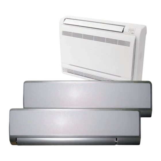
2. External Appearance Indoor units: Wall-mounted Console... -
Page 8: Outdoor Units
Outdoor units: HCKU 565 X2R HCKU 805 X3R HCKU 855 X4R... -
Page 9: Combination Of Indoor Units
3. Combination of Indoor Units You can choose different style indoor units: wall-mounted type, console type. 3.1 HCKU 565 X2R COOLING Nominal Cooling Total Cooling Power Input Combinations Capacity (kW) Capacity (kW) ENERGY LABEL Unit Unit Unit Unit Unit Unit... -
Page 10: Hcku 805 X3R
3.2 HCKU 805 X3R COOLING Nominal Cooling Total Cooling Power Input Combinations Capacity (kW) Capacity (kW) ENERGY LABEL Unit Unit Unit Unit Unit Unit Unit Unit min. std. max. min. std. max. (W/W) — — — 2,05 — — — 0,86 2,05 2,91... -
Page 11: Hcku 855 X4R
3.3 HCKU 855 X4R COOLING Nominal Cooling Total Cooling Power Input Combinations Capacity (kW) Capacity (kW) ENERGY LABEL Unit Unit Unit Unit Unit Unit Unit Unit min. std. max. min. std. max. (W/W) — — — 2,05 — — — 0,84 2,05 2,67... - Page 12 HEATING Nominal Heating Total Heating Power Input Combinations Capacity (kW) Capacity (kW) ENERGY LABEL Unit Unit Unit Unit Unit Unit Unit Unit min. std. max. min. std. max. (W/W) — — — 2,49 — — — 0,97 2,49 3,29 0,25 0,66 0,92 3,77 —...
-
Page 13: Features
4. Features Hokkaido’s DC multi air conditioner is new product series in Hokkaido brand. Adopt DC inverter compressor All the outdoor units use DC inverter compressor, the efficiency is high, the EER is up to A class. Various styles indoor units More than 6 different models indoor units can be chosen, including wall-mounted type, console type. - Page 14 Part 2 Indoor Units...
-
Page 15: Wall-Mounted Type
5. Wall-mounted Type 5.1 Specifications 5.1.1 Wall series Sale Model HKEU 265 XR HKEU 355 XR Power supply V-ph-Hz 220~240-1-50 220~240-1-50 Supply electricity type Outdoor unit supply power Capacity Btu/h 9000 12000 Cooling Input Rated current 0.17 Capacity Btu/h 10000 14000 Heating Input... -
Page 16: Dimensions
5.2 Dimensions Unit: mm Dimension Model HKEU 265 XR HKEU 355 XR... -
Page 17: Wiring Diagrams
6. Wiring Diagrams 7.1 HKEU 265-355 XR... -
Page 18: Air Velocity And Temperature Distributions
7. Air Velocity and Temperature Distributions Airflow velocity Temperature... -
Page 19: Electric Characteristics
8. Electric Characteristics Model Indoor Unit Power Supply Voltage HKEU 265 XR 220-240 0.21 0.02 0.17 HKEU 355 XR 220-240 0.25 0.02 0.17 Remark: MCA: Min. Current Amps. (A) MFA: Max. Fuse Amps. (A) KW: Fan Motor Rated Output (kW) FLA: Full Load Amps. -
Page 20: Sound Levels
9. Sound Levels Noise level dB(A) Model High speed HKEU 265 XR HKEU 355 XR... -
Page 21: Console Type
Console Type... -
Page 22: Features
10. Features Consumes up to 30% less energy than non-inverter units DC inverter compressor Indoor fan motor adopts DC motor Achieves set temperature more quickly Air supplying from top and bottom or from top only Air inlet from four directions Compact unit body, space saving This unit body is very thin and harmonious with room. -
Page 23: Specifications
11. Specifications Sale Model HFIU 205 XR HFIU 265 XR Power supply V-ph-Hz 220~240-1-50 220~240-1-50 Capacity Btu/h 7000 9000 Cooling Input Rated current 0.13 0.13 Capacity Btu/h 8000 10000 Heating Input Rated current 0.13 0.13 Model RD-280-20-8A RD-280-20-8A Type DC MOTOR DC MOTOR Indoor fan motor Brand... - Page 24 Sale Model HFIU 355 XR HFIU 535 XR Power supply V-ph-Hz 220~240-1-50 220~240-1-50 Capacity Btu/h 12000 18000 Cooling Input Rated current 0.13 0.22 Capacity Btu/h 14000 20000 Heating Input Rated current 0.13 0.22 Model RD-280-20-8A RD-280-20-8A Type DC MOTOR DC MOTOR Indoor fan motor Brand WELLING...
-
Page 25: Dimensions
12. Dimensions HFIU 205 XR、HFIU 265 XR、HFIU 355 XR、HFIU 535 XR... -
Page 26: Service Space
13. Service Space... -
Page 27: Wiring Diagrams
14. Wiring Diagrams HFIU 205 XR、HFIU 265 XR、HFIU 355 XR、HFIU 535 XR... -
Page 28: Air Velocity And Temperature Distributions
15. Air Velocity and Temperature Distributions Discharge angle 60 Airflow velocity Temperature... -
Page 29: Electric Characteristics
16. Electric Characteristics Indoor Unit Power Supply Model Voltage HFIU 205 XR 220-240 0.042 0.14 HFIU 265 XR 220-240 0.042 0.14 HFIU 355 XR 220-240 0.042 0.14 HFIU 535 XR 220-240 0.042 0.14... -
Page 30: Sound Levels
17. Sound Levels Noise level dB(A) Model HFIU 205 XR HFIU 265 XR HFIU 355 XR HFIU 535 XR... - Page 31 Part 3 Outdoor Units...
-
Page 32: Specifications
18. Specifications Outdoor Unit: Outdoor Model HCKU 565 X2R Power supply V-ph-Hz 220~240-1-50 Supply electricity type Outdoor unit supply power Capacity Kw/h 5.60 Cooling Input 1.643 Rated current Capacity Kw/h 6.98 Heating Input 1.773 Rated current Max. input consumption 2150 Max. - Page 33 Outdoor Model HCKU 805 X3R Power supply V-ph-Hz 220~240-1-50 Supply electricity type Outdoor unit supply power Capacity Kw/h 8.00 Cooling Input 2.405 Rated current Capacity Btu/h 9.80 Heating Input 2.50 Rated current 12.5 Max. input consumption 3200 Max. current Model JU1015D1 Type ROTARY...
- Page 34 Sale Model HCKU 855 X4R Supply electricity type Outdoor unit supply power Power supply V-ph-Hz 220~240-1-50 Capacity Kw/h 8.50 Cooling Input 2.613 Rated current 11.0 Capacity Kw/h 9.935 Heating Input 2.410 Rated current 14.5 Max. input consumption 4800 Max. current Model TNB220FLBM1 Type...
-
Page 35: Dimensions
19. Dimensions HCKU 565 X2R, HCKU 805 X3R, HCKU 855 X4R Unit: mm MODEL HCKU 565 X2R HCKU 805 X3R HCKU 855 X4R... -
Page 36: Service Space
20. Service Space... -
Page 37: Piping Diagrams
21. Piping Diagrams HCKU 565 X2R Axial flow fan EXVA Auxiliary Liquid valve A Filter A Capillary Exhaust Main Capillary A temp. sensor Capillary EXVB Check Liquid valve B Filter B Condenser Coil temp. Valve sensor Capillary B 4-way valve... - Page 38 Axial flow fan EXV2 HCKU 855 X4R Condenser EXV3 EXV4...
-
Page 39: Wiring Diagrams
22. Wiring Diagrams HCKU 565 X2R... - Page 40 HCKU 805 X3R...
- Page 41 HCKU 855 X4R...
-
Page 42: Field Wiring
23. Field Wiring... -
Page 43: Electric Characteristics
24. Electric Characteristics Model Outdoor Unit Power Supply Voltage Min. Max. TOCA HCKU 565 X2R 220-240 15.4 0.053 0.676 HCKU 805 X3R 220-240 0.053 0.676 HCKU 855 X4R 220-240 15.3 0.053 0.67 Remark: MCA: Min. Current Amps. (A) TOCA: Total Over-current Amps. (A) MFA: Max. -
Page 44: Operation Limits
25. Operation Limits For HCKU 565 X2R, HCKU 805 X3R Heating Indoor temp.(°C) - Page 45 Heatin For HCKU 855 X4R Indoor tempe...
-
Page 46: Sound Levels
26. Sound Levels Model Noise level dB(A) HCKU 565 X2R HCKU 805 X3R 59.5 HCKU 855 X4R 60.5... -
Page 47: Troubleshooting
27. Troubleshooting Indoor unit’s LED indication of Corona DC inverter unit Display LED STATUS EEPROM error outdoor communication error Zero-crossing examination error Fan speed beyond control Outdoor units temp. sensor or connector of temp. sensor is defective Indoor units temp. sensor or connector of temp. sensor is defective Inverter module protection Outdoor voltage protection Compressor top protection against temperature... - Page 48 Indoor unit trouble shooting Indoor unit display LED STATUS EEPROM error Circuit or software error on indoor PCB Replace indoor PCB Indoor unit display LED STATUS outdoor communication error Disconnect the power supply, after 1 minute, connect the power supply , turn on the unit with remote controller Does unit...
- Page 49 Indoor unit display LED STATUS Zero-crossing examination error Is power supply Be sure the power supply is connection of connectors good correct good? connection Indoor defective. Replace the indoor PCB. Indoor unit display LED STATUS Fan speed beyond control Is the indoor fan motor Repair the connector and connector and connection reconnect...
- Page 50 Indoor unit display LED STATUS Outdoor units temp. sensor or connector of temp. sensor is defective outdoor temperature sensor Repair the connector and connector reconnect connection good? Replace sensor Replace outdoor e-box and check if E5 display again? Indoor unit display LED STATUS Indoor units temp.
- Page 51 Indoor unit display LED STATUS Inverter module protection Revise the power and retest. Is voltage normal? Is all connection good? Revise the power and retest. wiring compressor right? Repair replace Check the moduler if moduler. some components blow out or be failure? Is it breakdown between P-N, P-V, P-W, N-V,N-W Replace the moduler.
- Page 52 Indoor unit display LED STATUS Compressor top protection against temperature Does Reconnect and retest. compressor connection operate? good? refrigerant protector Replace the protector. circulation normal? volume normal? Check the outdoor Charge main PCB. Is refrigerant there some problem? Replace the outdoor PCB Is abnormality the same after gas charging?
- Page 53 Outdoor unit’s LED indication Explanation Display EEPROM error No 1 Indoor units pipe temp. Sensor or connector of pipe temp. sensor is defective No 2 Indoor units pipe temp. Sensor or connector of pipe temp. sensor is defective No 3 Indoor units pipe temp. Sensor or connector of pipe temp. sensor is defective Outdoor temp.
- Page 54 Display Malfunction or Protection No 1 Indoor units pipe temp. Sensor or connector of pipe temp. sensor is defective E1(indoor unit) Repair connector Is connection to connector of pipe temp. Sensor good? Check the resistance of the temp. sensor according to Annex 1 Is the resistance normal? Replace the sensor Change main board...
- Page 55 Display Malfunction or Protection No 2 Indoor units pipe temp. Sensor or connector of pipe temp. sensor is defective E2(indoor unit) Is connection to connector of pipe temp. Repair connector Sensor good? Check the resistance of the temp. Sensor according to Annex 1 Is the resistance normal? Replace the sensor Change main board...
- Page 56 Display Malfunction or Protection No 3 Indoor units pipe temp. Sensor or connector of pipe temp. sensor is defective E3(indoor unit) Is connection to connector of pipe temp. sensor good? Repair connector Check the resistance of the temp. Sensor according to Annex 1 Is the resistance normal? Replace the sensor Change main board...
- Page 57 Display Malfunction or Protection Outdoor temp. Sensor or connector of temp. sensor is defective Is connection to connector of Outdoor temp. Sensor good? Repair connector Check the resistance of the temp. Sensor according to Annex 1 Is the resistance normal? Replace the sensor Change main board Display...
- Page 58 Display Malfunction or Protection No 4 Indoor units pipe temp. Sensor or connector of pipe temp. sensor is defective E3(indoor unit) Is connection to connector of pipe temp. Repair connector Sensor good? Check the resistance of the temp. Sensor according to Annex 1 Is the resistance normal? Replace the sensor Change main board...
- Page 59 Display Malfunction or Protection Communication malfunction between outdoor IC and DSP Change main board E7(outdoor unit) Display Malfunction or Protection Compressor discharge temperature protection When Compressor discharge temp. is more than 115°C, the unit will stop, and unit runs again when Compressor discharge temp.
- Page 60 Display Malfunction or Protection High pressure protection Outdoor master unit display P1; indoor unit alarm lamp flash slowly High/low pressure stop valve Error disappear opened completely or not? High pressure range during unit operating is Drop redundant refrigerant correct? The wire between pressure switch and main board Replace it Error disappear...
- Page 61 Display Malfunction or Protection Low pressure protection Outdoor master unit display P2; indoor unit alarm lamp flash slowly High/low pressure stop valve Error disappear opened completely or not? Low pressure range during Charge refrigerant unit operating is correct? The wire between pressure switch and main board works Error disappear Replace wire...
- Page 62 Display Malfunction or Protection Compressor current protection Check the resistance of compressor, normally U and V is 1 ohm U and W is 1 ohm V and W is 1ohm The compressor is defective Check the refrigerant circulation volume and pressure Recharge the refrigerant If refrigerant circulation volume and pressure is OK, change the outdoor main PCB.
- Page 63 (LED flashes for thirteen times) Malfunction or Protection Display Module protection Check the connectors CN4, CN1 in outdoor PCBs Is connection to connector good? Whether the input voltage range is 220-240V? Is the wires to compressor right Repair connector or Correct voltage Unplug the wiring to compressor, then restart, whether display the...
- Page 64 Malfunction or Protection Display Outdoor low temperature protection When outdoor temp. is lower than -15°C for more than 1 hour, the unit will stop, when the outdoor temp. is higher than -12°C for more than 10 minutes and the compressor has stopped for more than 1 hour,or the outdoor temp.
- Page 65 Display Malfunction or Protection Condenser high temperature protection When Condenser high temp. is more than 65°C, the unit will stop, and unit runs again when outdoor pipe temp. less than 52°C. Is the Condenser high temp. more than 65°C ? Is the Condenser high temp.
- Page 66 Part 4 Installation...
-
Page 67: Installation And Operation Instructions
28. Installation and operation instructions CAUTIONS For correct installation read this manual before starting installation and save this manual in a safe place for future reference. Only trained and qualified service personnel should install repair or service air conditioning equipment. Users should not install the air conditioner by themselves. -
Page 68: Precaution On Installation
Bend the tubing in proper way. Do not harm them. Specially Notice the pipe length/height/dimension of each capacity. Maximum pipe length Model Max. Length Max. Elevation HCKU 565 X2R HCKU 805 X3R HCKU 855 X4R Piping sizes Model Liquid(mm/inch) Gas(mm/inch) 6.35(1/4”) -
Page 69: Vacuum Dry And Leakage Checking
30. Vacuum dry and leakage checking Vacuum Dry: use vacuum pump to change the moisture (liquid) into steam (gas) in the pipe and discharge it out of the pipe to make the pipe dry. Under one atmospheric pressure, the boiling point of water (steam temperature) is 100 . - Page 70 ② Special vacuum dry procedure This vacuum dry method is used in the following conditions: There’s moisture when flushing the refrigerant pipe. Rainwater may enter into the pipe. Vacuum dry for the first time ······ 2h pumping ...
-
Page 71: Refrigerant Charge
31. Refrigerant charge 1). When the length of the one-way pipe is less than 5m, additional refrigerant charge after vacuuming is unnecessary. 2). When the length of one-way pipe is over 5m, the additional charge quantity is as follows (unit in gram): Calculation method: Refrigerant Unit amount (g/m) -
Page 72: Water Drainage
32. Water drainage 32.1 Gradient and Supporting Keep the drainpipe sloping downwards at a gradient of at least 1/100. Keep the drainpipe as short as possible and eliminate the air bubble. The horizontal drainpipe should be short. When the pipe is too long, a prop stand must be installed to keep the gradient of 1/100 and prevent bending. -
Page 73: Drainage Test
3) Selecting the diameter Number of connecting indoor units→Calculate drainage volume→Select the diameter Calculate allowed volume =Total cooling capacity of indoor units(HP)×2 (l/ hr) Allowed volume(lean 1/100) (l/ hr) I.D. (mm) Thick ∽≤14 ¢25 集中排水管 Hard PVC Hard PVC ¢30 14<∽≤88 Hard PVC ¢40... -
Page 74: Insulation Work
33. Insulation work 33.1 Insulation material and thickness Insulation material Insulation material should adopt the material which is able to endure the pipe’s temperature: no less than 70°C in the high-pressure side, no less than 120°C in the low-pressure side(For the cooling type machine, no requirements at the low-pressure side.) Example: Heat pump type----Heat-resistant Polyethylene foam (withstand above 120°C) Cooling only type---- Polyethylene foam (withstand above 100°C) -
Page 75: Drainage Pipe Insulation
Make sure there’s no clearance in the joining part of the accessorial insulation material and local preparative insulation material. 33.3 Drainage pipe insulation The connection part should be insulated, or else water will be condensing at the non-insulation part. 33.4 Note The jointing area, expanding area and the flange area should be heat insulated after passing the pressure test... -
Page 76: Test Operation
34. Test operation The test operation must be carried out after the entire installation has been completed. Please confirm the following points before the test operation. The indoor unit and outdoor unit are installed properly. Tubing and wiring are correctly completed. The refrigerant pipe system is leakage-checked. -
Page 77: Control System
Part 5 Control System... - Page 78 1.1 Electronic control function 1.1.1 Electric Control working environment. 1.1.1.1 Input voltage: 175~254V. 1.1.1.2 Input power frequency:50Hz. 1.1.1.3 Indoor fan normal working amp. is less than 1A. 1.1.1.4 Outdoor fan. Normal working amp. is less than 1.5A. 1.1.1.5 Four-way valve normal working amp. is less than 1A. 1.1.1.6 Swing motor: DC12V.
- Page 79 1.1.4 Outdoor unit point check function There is a check switch in outdoor PCB. Push the switch SW1 to check the states of unit when the unit is running. The digital display tube will display the follow procedure when push SW1 each time: Capacity demand→Running mode →revised capacity →...
- Page 80 Corresponding Corresponding Display Corresponding temp. Display Display temp. temp. 16.5 32.5 17.5 17.5 33.5 18.5 34.5 35~40 19.5 40~45 45~50 20.5 50~55 55~60 21.5 60~65 65~70 22.5 22.5 23.5 24.5 1.1.4.6 Outdoor pipe temp. Refers to 1.1.4.5 1.1.4.7Current of outdoor unit Display Corresponding mode 6.0 A...
- Page 81 12.0 A 12.2 A 1.1.4.8 No. 1 opening degree of electronic expansion valve: Opening degree equals the display data times 8 1.1.4.9 No. 2 opening degree of electronic expansion valve: Opening degree equals the display data times 8 1.1.4.10 No. 3 opening degree of electronic expansion valve: Opening degree equals the display data times 8 1.1.5 Protection...
- Page 82 1.1.7.3Anti-freezing control to indoor evaporator at cooling mode( T: evaporator temp. ) Evaporator Temp. Compressor °C T< 4 °C T > 8 1.1.8 Dehumidifying mode 1.1.8.1 the indoor fan is fixed in low speed 1.1.8.2 Low room temperature protection: When room temperature decreases to below 10°C, indoor fan stop, when room temperature restores to over 12°C, indoor fan start.
- Page 83 T= Indoor exchanger temp. T<48°C 53°C <T<63°C Decrease frequency of compressor T>63°C Defrosting operation (Available for heating only). 1.1.10 Defrost 1.1.10.1Defrosting condition: The temperature of outdoor heat exchanger remains consecutively lower than -2°c for more than 40 minutes, 1.1.10.2Ending condition of defrosting If one of following conditions is satisfied, end the defrost and turn into heating mode: a.
- Page 84 The set temperature decrease 1°C per hour. Two hours later, the set temperature will maintain as a constant and the air circulation is kept at low speed (Cold air proof function takes precedence over all). 1.1.14.4 Auto: The Sleep Mode running function operates in accordance with selected running mode by auto mode.
- Page 85 1.1.18 .2 Indoor unit error code explanation: Elite-panel LED4: operation LED1: auto LED2: timer LED3: defrost LED3 LED2 LED4 LED1AUTO LED state DEFR TIMER OPER ☆ Inverter module protection ☆ Compressor top temp. protection(PRCOM) ☆ Outdoor sensor open or short circuit ☆...
- Page 86 1.1.18 .3 Indoor unit error code explanation: cassette/duct/ceiling and floor Operation Timer De-frost Alarm State Indoor room temp. sensor open or short-circuit ★ Indoor pipe temp. sensor open or short-circuit Indoor and outdoor communication error ★ Water level alarm ...
- Page 87 Display LED STATUS EEPROM error No 1 Indoor units pipe temp. sensor or connector of pipe temp. sensor is defective No 2 Indoor units pipe temp. sensor or connector of pipe temp. sensor is defective No 3 Indoor units pipe temp. sensor or connector of pipe temp. sensor is defective Outdoor units temp.
-
Page 88: Control Device
35. Control device 2.1 Remote Controller 2.1.2 R51I4/BGE,R51I4/BGCE The model R51I4/BGE,R51I4/BGCE ,for hereinafter type:HKEU 265 XR, HKEU 355 XR The below is R51I4BGE, R51I4/BGCE remote controller Model R51I4BGE,R51I4/BGCE Rated voltage 3.0V(Dry batteries R03/LR03×2) Lowest voltage of CPU mitting signal 2.0V Signal receiving range 8m(whenusing3.0voltage,itGets11m) Environment...
Need help?
Do you have a question about the HCKU 565 X2R and is the answer not in the manual?
Questions and answers