
Related Manuals for Hokkaido HKEI-HCNI 263 XR


Summary of Contents for Hokkaido HKEI-HCNI 263 XR
-
Page 1: Service Manual
SERVICE MANUAL HOKKAIDO AIRCONDITIONER DC INVERTER SPLIT WALL-MOUNTED TYPE HKEI-HCNI 263 XR HKEI-HCNI 353 XR HKEI-HCNI 503 XR... -
Page 2: Table Of Contents
7.7 Balance refrigerant of the 2-way, 3-way valves ..........18 7.8 Evacuation ....................19 7.9 Gas charging ....................20 8. Operation characteristics ..................21 8.1 HKEI-HCNI 263 XR ..................21 8.2 HKEI-HCNI 353 XR ..................22 8.3 HKEI-HCNI 503 XR ..................23 9. Electronic function....................24 9.1 Abbreviation ....................24... - Page 3 9.3.1.2 Temperature protection of compressor top..........25 9.3.1.3 If the temperature of compressor top is too high ........25 9.3.1.4 Inverter module Protection ..............25 9.3.1.5 Sensor protection at open circuit ............25 9.3.1.6 Fan Speed is out of control..............25 9.3.1.7 Cross Zero signal error warning............25 9.3.1.8 Indoor fan delayed open function ............25 9.3.1.9 For all modes, when the units are turned on ..........25 9.3.1.10 Compressor preheating function.
- Page 4 9.10 Action of 4-way valve ..................32 9.11 Two speeds outdoor fan function ..............33 9.11.1 Outdoor fan starts at the same time with compressor ......33 9.11.2 Outdoor fan action in heating mode ............33 9.11.3 Outdoor fan action in cooling & drying mode ...........33 9.12 Timer function ....................33 9.12.1 Timing range is 24 hours ..............33 9.12.2 Timer on.
-
Page 5: Precaution
1. Precaution There is risk of fire, electric shock, explosion, or 1.1 Safety Precaution injury. To prevent injury to the user or other Do not install the product on a people and property damage, the following defective installation stand. It may cause injury, accident, or damage to the instructions must be followed. - Page 6 A bad connection may cause water leakage. comes from product. Turn the breaker off or Keep level even when installing the disconnect the power supply cable. product. There is risk of electric shock or fire. To avoid vibration of water leakage. Stop operation and close the window ...
- Page 7 malfunction or damage. different types of batteries. Do not insert hands or other object There is risk of fire or explosion. through air inlet or outlet while the product Do not recharge or disassemble the is operated. batteries. Do not dispose of batteries in a There are sharp and moving parts that could fire.
-
Page 8: Function
2. Function Indoor unit Operation by remote controller Sensing by room temperature temperature Room temperature sensor. Pipe temperature sensor. Room temperature control Maintain the room temperature in accordance with the setting temperature. Anti-freezing control in cooling Prevent the water being frozen on evaporator by sensing the evaporator pipe temperature in cooling mode Time Delay Safety control Restarting is for approx. - Page 9 Outdoor unit Power relay control The unit has 3 mins delay between continuously ON/OFF operations. Low noise air flow system Bird tail propeller fan makes the outdoor unit run more quietly. Hydrophilic aluminum fin The hydrophilic fin can improve the heating efficiency at operation mode. 4 way valve control It is only operated in the heating operation mode except defrosting operation.
-
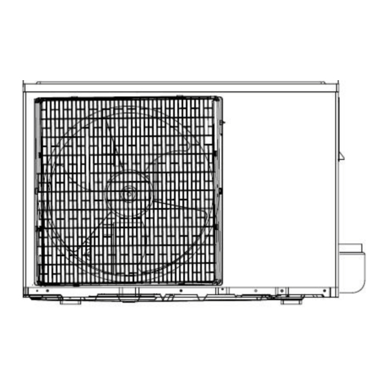
Page 10: Dimension
3. Dimension 3.1 Indoor Unit HKEI 263-353-503 XR Dimension Model 263/353 3.2 Outdoor Unit HCNI 263 XR... - Page 11 HCNI 353 XR HCNI 503 XR HCNI 503 XR...
-
Page 12: Specification
4. Specification Indoor HKEI 263 XR HKEI 353 XR HKEI 503 XR Outdoor HCNI 263 XR HCNI 353 XR HCNI 503 XR Power supply Ph-V-Hz 1,220-240V~,50Hz 1, 220-240V~, 50Hz 1, 220-240V~, 50Hz Capacity 2,60 (0,66~2,92) 3,50 (0,71~3,94) 5,07 (2,77~5,70) Input 800 (180~1100) 1010 (210~1380) 1570 (730~1780) -
Page 13: Refrigerant Cycle Diagram
5. Refrigerant cycle diagram... -
Page 14: Wiring Diagram
6. Wiring diagram 6.1 Indoor Unit HKEI 263 XR HKEI 353 XR HKEI 503 XR... -
Page 15: Outdoor Unit
6.2 Outdoor Unit HCNI 263 XR... -
Page 16: Hcni 353 Xr Xr
HCNI 353 XR... -
Page 17: Hcni 503 Xr
HCNI 503 XR... -
Page 18: Installation Details
7. Installation details 7.1 Wrench torque sheet for installation Outside diameter Torque inch Kgf·m Ф6.35 Ф9.52 Ф12.7 7.2 Connecting the cables The power cord of connect should be selected according to the following specifications sheet. Grade Unit 7.3 Pipe length and the elevation Standard Max. -
Page 19: Air Purging Of The Piping And Indoor Unit
7.4 Air purging of the piping and indoor unit Required tools: Hexagonal wrench; adjustable wrench; torque wrenches, wrench to hold the joints and gas leak detector. Note: The air in the indoor unit and in the piping must be purged. If air remains in the refrigeration piping, it will affect the compressor, reduce the cooling capacity, and could lead to a malfunction of unit. -
Page 20: Pumping Down (Re-Installation)
7.5 Pumping down (Re-installation) Procedure 1. Confirm that both the 2-way and 3-way valves are set to the opened position. Remove the valve stem caps and confirm that the valve stems are in the opened position. Be sure to use a hexagonal wrench to operate the valve stems. 2. -
Page 21: Re-Air Purging (Re-Installation)
7.6 Re-air purging (Re-installation) Procedure: 1. Confirm that both the 2-way and 3-way valves are set to the closed position. 2. Connect the charge set and a charging cylinder to the service port of the 3-way valve. Leave the valve on the charging cylinder closed. 3. -
Page 22: Balance Refrigerant Of The 2-Way, 3-Way Valves
7.7 Balance refrigerant of the 2-way, 3-way valves Procedure: 1. Confirm that both the 2-way and 3-way valves are set to the open position. 2. Connect the charge set to the 3-way valve’s service port. Leave the valve on the charge set closed. Connect the charge hose with the push pin to the service port. -
Page 23: Evacuation
7.8 Evacuation Procedure: 1. Connect the vacuum pump to the charge set’s centre hose. 2. Evacuation for approximately one hour. Confirm that the gauge needle has moved toward -0.1 Mpa (-76 cmHg) [vacuum of 4 mmHg or less]. 3. Close the valve (Low side) on the charge set, turn off the vacuum pump, and confirm that the gauge needle does not move (approximately 5 minutes after turning off the vacuum pump). -
Page 24: Gas Charging
7.9 Gas charging Procedure: 1. Connect the charge hose to the charging cylinder. Connect the charge hose which you disconnected from the vacuum pump to the valve at the bottom of the cylinder. 2. Purge the air from the charge hose. Open the valve at the bottom of the cylinder and press the check valve on the charge set to purge the air (be careful of the liquid refrigerant). -
Page 25: Operation Characteristics
8. Operation characteristics 8.1 HKEI-HCNI 263 XR Piping Length Characteristics (Cooling) Cooling Characteristics 2.52 2.62 2.48 2.58 2.44 2.54 2.40 2.50 2.36 2.46 2.32 2.42 2.28 2.38 2.24 2.34 0.78 0.86 0.76 0.80 0.74 0.78 0.72 0.76 0.70 0.74 0.68 0.72... -
Page 26: Hkei-Hcni 353 Xr
8.2 HKEI-HCNI 353 XR Piping Length Characteristics (Cooling) Cooling Characteristics 3.20 3.12 3.04 2.96 2.88 2.80 2.72 2.64 0.99 1.08 0.96 1.04 0.93 1.00 0.90 0.96 0.87 0.92 0.84 0.88 0.84 0.81 10 11 12 13 14 25 27 29 31 33 35 37 39 41 43 Piping Length Outdoor Ambient... -
Page 27: Hkei-Hcni 503 Xr
8.3 HKEI-HCNI 503 XR Piping Length Cooling Characteristics Characteristics (Cooling) 1.58 1.68 1.56 1.64 1.54 1.60 1.52 1.56 1.50 1.52 1.48 1.48 1.44 1.46 10 11 12 13 14 25 27 29 31 33 35 37 39 41 43 Piping Length Outdoor Ambient Temperature Remark: Indoor room temperature: Remark: Indoor room temperature:... -
Page 28: Electronic Function
9. Electronic function 9.1 Abbreviation T1: Indoor ambient temperature T2: Pipe temperature of indoor heat exchanger T3: Pipe temperature of outdoor heat exchanger T4: Outdoor ambient temperature 9.2 Display function 9.2.1 Icon explanation on indoor display board. HKEI 263-353-503 XR ①... -
Page 29: Protection
9.3 Protection 9.3.1 Models 263-353 XR 9.3.1.1 Three Minutes Delay at restart for compressor. 9.3.1.2 Temperature protection of compressor top. 9.3.1.3 If the temperature of compressor top is too high (higher than 120℃) and the Over-load Protector is cut, the units stop. -
Page 30: Protection (Model 503 Xr)
9.3.2 Model 503 XR 9.3.2.1 Three Minutes Delay at restart for compressor. 9.3.2.2 Temperature protection of compressor top. 9.3.2.3 If the temperature of compressor top is too high (higher than 115℃ and the Over-load Protector is cut, the units stop. When the Over-load Protector restore and close (lower than 100℃), the compressor will restart( in this case the compressor is restricted by Three Minutes Delay protection. -
Page 31: Fan-Only Mode
9.4 Fan-Only Mode 9.4.1 Temperature setting function is disabled, and no setting temperature display. 9.4.2 In this mode, the action of louver is the same as in cooling mode. 9.4.3 The action of auto fan in fan-only mode is the same as auto fan in cooling mode with 24℃ setting temperature. ℃... -
Page 32: Outdoor Unit Current Control In Cooling Mode
9.5.3 Outdoor unit current control in cooling mode(refer to the parameter table) comp. pause I3CO freq. descends if curr. rises; I2CO freq. remains if curr. descends I1CO running normally Remark: Model I1COOL I2COOL I3COOL 263-353 5.0 A 6.0 A 7.0 A 9.5 A 10.5 A 13 A... -
Page 33: Condenser High Temperature
9.5.7 Condenser high temperature protection function (in cooling and drying mode) If T3>60℃ for 5 seconds, compressor will stop immediately, and the machine will not resume until T3<52℃. 9.6 Drying mode 9.6.1 Indoor fan speed is fixed at breeze grade and can’t be changed. The horizontal angle is the same as in cooling mode. -
Page 34: After Start The Operation Frequency
9.7.3 After start the operation frequency of compressor submits to following rule: ℃ 0 4. Remark: ΔTcon can be changed among 0, -2,- 4℃, the default is 0℃ When the machine runs, if ΔTh stays in a zone for 3 minutes, action of frequency is as follow: Zone A: Elevate the current frequency one grade, and not stop until the maximum grade. -
Page 35: Defrosting Mode
9.7.6 Defrosting mode. Condition of defrosting. Condition 1: If T4>0℃, When the units are running, if the following two items are satisfied the units start defrosting: The units runs with T3<3℃ for 40 minutes and T3 keeps lower than -6℃ for more than 3 minutes. The units runs with T3<3℃... -
Page 36: Auto Mode Function
Turbo function in heating mode. (press the “TURBO” button on remote controller) Elevate current frequency (excluding F8) to a higher grade. If indoor fan is in low speed or pause caused by defrosting or anti-cold-wind function, frequency of compressor will not be elevated one grade until these limit has been released. Indoor fan changes to turbo speed and anti-cold-wind function is valid. -
Page 37: Two Speeds Outdoor Fan Function
9.11 Two speeds outdoor fan function 9.11.1 Outdoor fan starts at the same time with compressor, but stops 30 seconds later than compressor ‘s stop. 9.11.2 Outdoor fan action in heating mode (including heating in auto mode). ℃ ℃ high Outdoor fan action in heating Outdoor fan action in cooling &... -
Page 38: Outdoor Chassis Heating Cable (Optional)
9.15 Outdoor chassis heating cable (optional) Heating cable is fixed on outdoor chassis to help deicing and to avoid freezing. The heating cable’s power is 85W, rated voltage is 220V-240V, and is controlled by the program. If outdoor temperature is lower than 5℃, the heating cable will begin to work. If outdoor temperature is higher than 15℃, the heating cable will stop working. -
Page 39: Troubleshooting
10. Troubleshooting Safety Because of there are capacitors in PCB and relative circuit in outdoor unit, even shut down the power supply, electricity power still are kept in capacitors, do not forget to discharge the electricity power in capacitor. Electrolytic Capacitors (HIGH VOLTAGE! CAUTION!) Bulb (25-40W) -
Page 40: Indoor Unit Error Display
10.1 Indoor Unit Error Display Display LED STATUS EEPROM parameter error Indoor / outdoor units communication protection Zero-crossing signal error Fan speed out of control Open or short circuit of outdoor ambient or condenser temperature sensor Open or short circuit of indoor room or evaporator temperature sensor Inverter module (IGBT) over-strong current protection Over voltage or too low voltage protection Temperature protection of compressor top. -
Page 41: Diagnosis And Solution
10.2 Diagnosis and Solution 10.2.1 E0 (EEPROM parameter error) error diagnosis and solution Circuit or software error on indoor Replace indoor PCB 10.2.2 E1 (indoor / outdoor units communication protection) error diagnosis and solution Disconnect the power supply, after 1 minute, connect the power supply , turn on the unit with remote controller Does the unit work... -
Page 42: E2 (Zero-Crossing Signal Error) Diagnosis And Solution
10.2.3 E2 (zero-crossing signal error) diagnosis and solution Is power supply and Be sure the power supply is connection of good and correct the connectors good? connection Indoor PCB is defective. Replace the indoor PCB. 10.2.4 E3 (indoor fan speed out of control) diagnosis and solution Is the indoor fan motor Repair the connector and connector and... -
Page 43: P0 (Igbt Over-Strong Current Protection) Diagnosis And Solution
10.2.6 E6 (open or short circuit of indoor room or evaporator temperature sensor) diagnosis and solution. Is the indoor Repair the connector and temperature and reconnect evaporator sensor connector and connection good? Replace the.indoor PCB Replace the sensor and check if E6 display again? 10.2.7 P0 (IGBT over-strong current protection) diagnosis and solution. -
Page 44: P2 (Temperature Protection Of Compressor Top) Diagnosis And Solution
10.2.9 P2 (temperature protection of compressor top) diagnosis and solution. Is the Does Reconnect and connection compressor retest. good? operate? Is refrigerant Is protector Replace the protector. circulation normal? volume normal? Check the Charge outdoor main refrigerant PCB. Is there some problem? Replace the outdoor PCB. -
Page 45: Key Parts Checking
10.3 Key parts checking. 10.3.1. Compressor checking Measure the resistance value of each winding by using the multi-meter. Position Resistance Value Blue - Red HCNI 503 HCNI 263-353 0.668Ω Blue - Black 1.10Ω (25℃) Red - Blue (20℃) 10.3.2 Outdoor Fan Motor Measure the resistance value of each winding by using the multi-meter. -
Page 46: Step Motor (Model: Mp24Ga)
10.3.4 Step Motor (Model: MP24GA). Measure the resistance value of each winding by using the multi-meter. Position Resistance Value Blue - Red Pink - Orange 200Ω±7% (25℃) for 263-353 Pink - Yellow Yellow - Red... -
Page 47: Temperature Sensors
10.3.5 Temperature Sensors. Room temp.(T1) sensor, Indoor coil temp.(T2) sensor, Outdoor coil temp.(T3) sensor, Outdoor ambient temp.(T4) sensor, Compressor exhaust temp.(Te) sensor. Measure the resistance value of each winding by using the multi-meter. Some frequently-used R-T data for T1,T2,T3 and T4 sensor: Temperature (℃) Resistance Value (KΩ) 26.9...
Need help?
Do you have a question about the HKEI-HCNI 263 XR and is the answer not in the manual?
Questions and answers