JVC KS-AX4500 Service Manual
Power amplifier
Hide thumbs
Also See for KS-AX4500:
- Instructions manual (21 pages) ,
- Service manual (28 pages) ,
- Service manual (28 pages)
Advertisement
Quick Links
SERVICE MANUAL
Caution
If electricity is connected during disassembly, it must be a no load current. If it is load
current, be sure to attach a heat sink to the power-amp IC. This will be damaged if the
above precautions are not followed, as it does not have a sub heat sink attached to it.
Contents
Safety precaution
Location of main parts
Removal of main parts
Test method
Description of major ICs
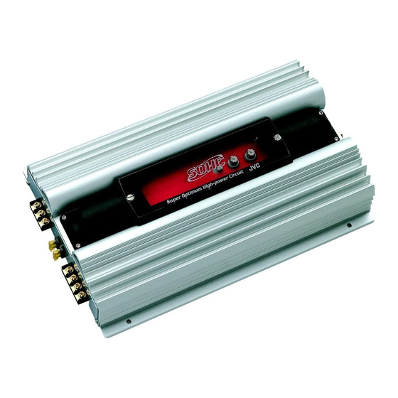
POWER AMPLIFIER
KS-AX4500
1-2
1-3
1-5
1-7
1-8
COPYRIGHT
2001 VICTOR COMPANY OF JAPAN, LTD.
KS-AX4500
Area Suffix
Continental Europe
E
J
Northern America
No. 49622
Apr. 2001
Advertisement

Related Manuals for JVC KS-AX4500


Summary of Contents for JVC KS-AX4500
-
Page 1: Service Manual
KS-AX4500 SERVICE MANUAL POWER AMPLIFIER KS-AX4500 Area Suffix Continental Europe Northern America Caution If electricity is connected during disassembly, it must be a no load current. If it is load current, be sure to attach a heat sink to the power-amp IC. This will be damaged if the above precautions are not followed, as it does not have a sub heat sink attached to it. - Page 2 KS-AX4500 ! CAUTION Burrs formed during molding may be left over on some parts of the chassis. Therefore, pay attention to such burrs in the case of preforming repair of this system.
- Page 3 KS-AX4500 Location of main parts HEAT SINK CONTROL PANEL SWITCH KNOB VOLUME KNOB HEAT SINK REAR PANEL FUSE INPUT for POWER OUTPUT TERMINAL for REAR(L/R) OUTPUT TERMINAL for FRONT(L/R) LOW INPUT jack for REAR(R) LOW INPUT jack for FRONT(R) HEAT SINK...
- Page 4 KS-AX4500 HEAT SINK (Bottom view) GND wire MAIN PCB SUB PCB POWER TRANSISTER DIODE POWER FET POWER TRANSISTER MAIN PCB...
- Page 5 KS-AX4500 Removal of main parts CAUTION: If electricity is connected during disassembly, Bottom cover it must be a no load current. If it is load current, be sure to attach a heat sink to the power-amp IC. This will be damaged if the above precautions are not followed, as it does not have a sub heat sink attached to it.
- Page 6 KS-AX4500 Remove the 13 screws E retaining the panels on both sides of the main unit. Rear panel Fig. 5 Front panel Fig. 6 Remove the 14 screws F attaching the MAIN PCB to the bottom of the main unit.
- Page 7 KS-AX4500 Test method Check the voltage and frequency of the secondary FREQUENCY COUNTER toroidal coil. FREQUENCY:22.87kHz ± 50Hz VOLTAGE VALUE:60Vp-p ± 2.5V TEST SET POWER SUPPLY 14.4V MAIN PCB Measuring Points 2. Measure the secondary toroidal coil, if the standard frequency value of 22.87 kHz ±...
- Page 8 KS-AX4500 Description of major ICs PIN CONNECTIONS Noninv Noninv Input Input Input Input Compen/PWN V ref Comp Input Dead Time Output Control Control V CC Ground (TOP View) TL494 Oscillator Flip- Dead-Time Flop Comparator 0.12V 0.7V 4.9V 0.7mA Comparator Lockout...
- Page 9 KS-AX4500 VICTOR COMPANY OF JAPAN, LIMITED MOBILE ELECTRONICS DIVISION PERSONAL & MOBILE NETWORK B.U. 10-1,1Chome,Ohwatari-machi,Maebashi-city,Japan Printed in Japan (No. 49622) 200104(S)
Need help?
Do you have a question about the KS-AX4500 and is the answer not in the manual?
Questions and answers