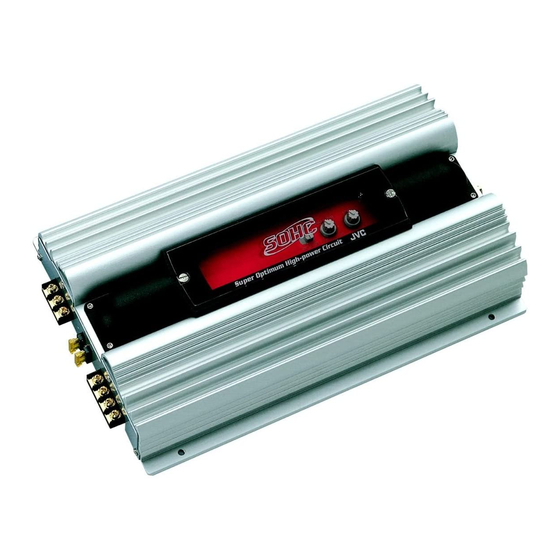
JVC KS-AX4500 Service Manual
Hide thumbs
Also See for KS-AX4500:
- Instructions manual (21 pages) ,
- Service manual (9 pages) ,
- Service manual (28 pages)
Table of Contents
Advertisement
QQ
3 7 63 1515 0
SERVICE MANUAL
TE
L 13942296513
Caution
If electricity is connected during disassembly, it must be a no load current. If it is load
current, be sure to attach a heat sink to the power-amp IC. This will be damaged if the
above precautions are not followed, as it does not have a sub heat sink attached to it.
Contents
Safety precaution
Location of main parts
Removal of main parts
Test method
Description of major ICs
www
.
http://www.xiaoyu163.com
POWER AMPLIFIER
KS-AX4500
x
ao
u163
y
i
COPYRIGHT
2001 VICTOR COMPANY OF JAPAN, LTD.
http://www.xiaoyu163.com
2 9
8
Q Q
3
6 7
1 3
1 5
1-2
1-3
1-5
1-7
1-8
co
.
KS-AX4500
9 4
2 8
0 5
8
2 9
9 4
2 8
Area Suffix
Continental Europe
E
J
Northern America
m
No. 49622
9 9
9 9
Apr. 2001
Advertisement
Table of Contents

Related Manuals for JVC KS-AX4500


Summary of Contents for JVC KS-AX4500
-
Page 1: Service Manual
KS-AX4500 3 7 63 1515 0 SERVICE MANUAL POWER AMPLIFIER KS-AX4500 L 13942296513 Area Suffix Continental Europe Northern America Caution If electricity is connected during disassembly, it must be a no load current. If it is load current, be sure to attach a heat sink to the power-amp IC. This will be damaged if the above precautions are not followed, as it does not have a sub heat sink attached to it. - Page 2 KS-AX4500 3 7 63 1515 0 ! CAUTION Burrs formed during molding may be left over on some parts of the chassis. Therefore, pay attention to such burrs in the case of preforming repair of this system. L 13942296513 u163 http://www.xiaoyu163.com...
-
Page 3: Location Of Main Parts
KS-AX4500 3 7 63 1515 0 Location of main parts HEAT SINK CONTROL PANEL SWITCH KNOB VOLUME KNOB L 13942296513 HEAT SINK REAR PANEL FUSE INPUT for POWER OUTPUT TERMINAL for REAR(L/R) OUTPUT TERMINAL for FRONT(L/R) LOW INPUT jack for REAR(R) - Page 4 KS-AX4500 3 7 63 1515 0 HEAT SINK (Bottom view) GND wire MAIN PCB SUB PCB POWER TRANSISTER DIODE L 13942296513 POWER FET POWER TRANSISTER MAIN PCB u163 http://www.xiaoyu163.com...
-
Page 5: Removal Of Main Parts
KS-AX4500 3 7 63 1515 0 Removal of main parts CAUTION: If electricity is connected during disassembly, Bottom cover it must be a no load current. If it is load current, be sure to attach a heat sink to the power-amp IC. - Page 6 KS-AX4500 3 7 63 1515 0 Remove the 13 screws E retaining the panels on both sides of the main unit. Rear panel Fig. 5 Front panel Fig. 6 Remove the 14 screws F attaching the MAIN PCB to the bottom of the main unit.
-
Page 7: Test Method
KS-AX4500 3 7 63 1515 0 Test method Check the voltage and frequency of the secondary FREQUENCY COUNTER toroidal coil. FREQUENCY:22.87kHz ± 50Hz VOLTAGE VALUE:60Vp-p ± 2.5V TEST SET POWER SUPPLY 14.4V MAIN PCB Measuring Points 2. Measure the secondary toroidal coil, if the standard frequency value of 22.87 kHz ±... -
Page 8: Description Of Major Ics
KS-AX4500 3 7 63 1515 0 Description of major ICs PIN CONNECTIONS Noninv Noninv Input Input Input Input Compen/PWN V ref Comp Input Dead Time Output Control Control V CC Ground L 13942296513 (TOP View) TL494 Oscillator Flip- Dead-Time... - Page 9 KS-AX4500 http://www.xiaoyu163.com 3 7 63 1515 0 L 13942296513 u163 VICTOR COMPANY OF JAPAN, LIMITED MOBILE ELECTRONICS DIVISION PERSONAL & MOBILE NETWORK B.U. 10-1,1Chome,Ohwatari-machi,Maebashi-city,Japan Printed in Japan (No. 49622) 200104(S) http://www.xiaoyu163.com...
-
Page 10: Circuit Block Diagram
KS-AX4500 3 7 63 1515 0 Circuit block diagram L 13942296513 u163 http://www.xiaoyu163.com... - Page 11 KS-AX4500 3 7 63 1515 0 MEMO L 13942296513 u163 http://www.xiaoyu163.com...
-
Page 12: Standard Schematic Diagrams
KS-AX4500 3 7 6 3 1 5 1 5 0 Standard schematic diagrams MAIN PCB [1/3] and SUB PCB circuit diagrams 20Ax2 TM0006-00 A1023Y 10/0.25W CL-310 UC400962 CHASSIS 104(M) 4.7K 10/16V 1N5404 130KF 4.7K 104P 104P 104P C3198GR 51KF... - Page 13 KS-AX4500 3 7 6 3 1 5 1 5 0 MAIN PCB [2/3] and SUB PCB circuit diagrams +15V R333 R337 R343 C333 Q305 R334 +15V 22/16V Q301 A1268GR Q310 5.6K Q308 +15V C335 Q302 C3198GR D998 C1027Y 150P...
- Page 14 KS-AX4500 3 7 6 3 1 5 1 5 0 MAIN PCB [3/3] circuit diagrams +15V R137 R143 R133 R134 C133 Q105 +15V 5.6K 22/16V Q101 A1268GR Q110 Q102 Q108 C135 +15V C3198GR C3198GR D998 C1027Y 150P C114 104(M)
-
Page 15: Printed Circuit Boards
KS-AX4500 3 7 6 3 1 5 1 5 0 Printed circuit boards MAIN PCB Surface side view KS-AX4500 PPM028-01 REV.0 R263 R163 TH01 C191 J116 C205 C105 C291 JA02 BJ05 BJ06 1 3 9 4 2 2 9 6 5 1 3... - Page 16 KS-AX4500 3 7 6 3 1 5 1 5 0 Bottom side view COMPONENT COMPONENT COMPONENT COMPONENT COMPONENT COMPONENT COMPONENT COMPONENT COMPONENT COMPONENT COMPONENT COMPONENT COMPONENT COMPONENT COMPONENT COMPONENT COMPONENT COMPONENT COMPONENT COMPONENT COMPONENT COMPONENT COMPONENT COMPONENT COMPONENT COMPONENT...
- Page 17 KS-AX4500 3 7 6 3 1 5 1 5 0 SUB PCB (Volume board) Surface side view COMPONENT COMPONENT COMPONENT COMPONENT COMPONENT COMPONENT COMPONENT COMPONENT COMPONENT COMPONENT KS-AX4500 KS-AX4500 SW301 SW101 HP03 PPS-037-01 HP04 REV.0 HP02 HP01 VR301 VR302...
-
Page 18: Parts List
KS-AX4500 3 7 63 1515 0 PARTS LIST KS-AX4500 * All printed circuit boards and its assemblies are not available as service parts. Areas suffix E ------------ Continental Europe J -------------- Northern America L 13942296513 - Contents - Exploded view of enclosure assembly and parts list... -
Page 19: Exploded View Of Enclosure Assembly And Parts List
KS-AX4500 3 7 63 1515 0 Exploded view of enclosure assembly and parts list Block No. L 13942296513 15 14 u163 http://www.xiaoyu163.com... - Page 20 KS-AX4500 3 7 63 1515 0 Parts list ( Enclosure assembly ) Block No. M1MM Item Parts number Parts name Q'ty Description Area MAIN HEAT SINK MA-HS-IT-1123-1 MA-FP-IT-6411-1 FRONT PANEL MA-RP-IT-6412-1 REAR PANEL BOTTOM COVER MA-BC-IT-6415-2 MA-SD-06-1924-0 CONTROL PANEL...
-
Page 21: Electrical Parts List
KS-AX4500 Electrical parts list 3 7 63 1515 0 Electrical parts list (P.C.board) Block No. 01 Item Parts number Parts name Remarks Area Item Remarks Parts number Parts name Area C 01 ELE10UF/16V E.CAPACITOR ELECTROLYTIC C 139 ELE100UF/16V E.CAPACITOR... - Page 22 KS-AX4500 3 7 63 1515 0 Electrical parts list (P.C.board) Block No. 01 Item Remarks Item Remarks Parts number Parts name Area Parts number Parts name Area C 316 MAL473J/50V M.CAPACITOR MYLAR 50V 5% D 02 1N4004 DIODE RECTIFIER...
- Page 23 KS-AX4500 3 7 63 1515 0 Electrical parts list (P.C.board) Block No. 01 Item Parts number Parts name Remarks Area Item Parts number Parts name Remarks Area Q 203 KTA1266GR TRANSISTOR SMALL SIGNAL PN R 43 CAR1/4WJ220 RESISTOR CARBON FILM 1/4...
- Page 24 KS-AX4500 3 7 63 1515 0 Electrical parts list (P.C.board) Block No. 01 Item Remarks Item Remarks Parts number Parts name Area Parts number Parts name Area R 154 CAR1/5WJ56K RESISTOR CARBON FILM 1/5 R 309 SMD1/5WF1.3K RESISTOR SMD 0805 1/5WF R 155 MET1/2WJ4.7...
- Page 25 KS-AX4500 3 7 63 1515 0 Electrical parts list (P.C.board) Block No. 01 Item Parts number Parts name Remarks Area R 421 SMD1/5WJ30K RESISTOR SMD 0805 1/5WJ R 422 SMD1/5WJ30K RESISTOR SMD 0805 1/5WJ R 423 SMD1/5WJ30K RESISTOR SMD 0805 1/5WJ...
-
Page 26: Packing And Accessories
KS-AX4500 3 7 63 1515 0 Packing and accessories Block No. Block No. L 13942296513 A1,A2,A7,A8 u163 http://www.xiaoyu163.com... -
Page 27: Packing Parts List
KS-AX4500 3 7 63 1515 0 Packing parts list Block No. M2MM Item Parts number Parts name Q'ty Description Area MA-GB-02-6419-0 GIFT BOX CUSHION MA-SN-07-1116-0 MA-PB-01-1039-0 POLY BAG-A MA-PB-01-1524-1 POLY BAG-D MA-PB-01-1715-0 POLY BAG-B MA-PB-01-4101-0 POLY BAG-C PAPER SPACER...
Need help?
Do you have a question about the KS-AX4500 and is the answer not in the manual?
Questions and answers