
Subscribe to Our Youtube Channel
Related Manuals for Centralion 1000VA


Summary of Contents for Centralion 1000VA
-
Page 1: User Manual
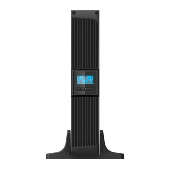
USER MANUAL Line Interactive UPS 1000VA/1500VA/2000VA/3000VA Uninterruptible Power Supply System... -
Page 2: Save These Instructions
INSTRUCTIONS SAVE THESE INSTRUCTIONS This manual contains important instructions 1000VA/1500VA/2000VA/3000VA series that should followed during installation and maintenance of the UPS and batteries. Please read all safety and operating instructions before operating the UPS. Adhere to all warnings on the unit and in this manual. And follow all... -
Page 3: Table Of Contents
CONTENTS 1. Introduction ······························································································· 1 2. Safety Warning ··························································································· 2 2.1 Description of Commonly Used Symbols ····················································· 3 3. Installation ································································································· 4 3.1 Inspection of Unit ···················································································· 4 3.2 Unpacking the Cabinet ············································································· 4 3.3 UPS Setup ···························································································· 4 3.4 EBM Installation (Optional) ······································································· 9 3.5 UPS Initial Startup ·················································································... -
Page 4: Introduction
UPS self test sequence as well. The UPS case for 1000VA ~ 3000VA is made of metal. This series is powered from the AC mains and supply AC outputs via receptacles on the rear panel. Communication and control of UPS is available through serial or USB ports located on the rear panel. -
Page 5: Safety Warning
2. Safety Warning DANGER: This UPS contains high voltages. All repairs and service should be performed by authorized service personnel only. There are no user serviceable parts inside the UPS. WARNING: This UPS contains its own energy source (batteries).The UPS output may carry live voltage even when the UPS is not connected to an AC supply. -
Page 6: Description Of Commonly Used Symbols
Following figure shows the basic internal circuit configuration of the UPS 2.1 Description of Commonly Used Symbols Some or all of the following Notations may be used in this manual and may appear in your application process. Therefore, all users should be familiar with them and understand their explanations. -
Page 7: Installation
3. Installation 3.1 Inspection of Unit Inspect the UPS upon receiving. If the UPS is apparently damaged during the shipment, please keep the box and packing material in original form for the carrier and notify the carrier and dealer immediately. 3.2 Unpacking the Cabinet To unpack the system: 1. - Page 8 Use the following procedure to install UPS in UPS stands. 1. Slide down the UPS vertically and put two UPS stands at the end of the tower. 2. Place down the UPS into two stands carefully.
- Page 9 3. Pull out the LCD box and rotate it in a clockwise direction to 90 degree and then push it back in the front panel.
- Page 10 Rack-mount setup The series can be installed in 19 inches racks. Both the UPS and external battery enclosure need 2U of valuable rack space. Use the following procedure to install UPS in a rack. 1. Align the mounting ears with screw holes on the side of the UPS, and tighten the screw.
- Page 11 3. Slide in the UPS into the rack rail and lock it in the rack enclosure. 4. Tighten the screw, and the load can then be connected.
-
Page 12: Ebm Installation (Optional)
3.4 EBM Installation (Optional) Connecting the EBM in Tower form: 1. Slide down the UPS and EBM vertically and place two UPS stands with the extend part at the end of the tower. 2. Tighten the screw on the metal sheet for stabilization 3. - Page 13 4. Take off the front panel, and connect the battery terminal (A) from UPS to EBM terminal (B) shown as below. Users need to remove the small gate(C) on side of the front panel to allow the outlet wire of the EBM to pass through the gate and then reassemble front panel.
- Page 14 2. Connect the earth line from UPS (port A ) to EBM (port B ) 3. Take off the LCD box, and unscrew the internal screws. Unscrew...
- Page 15 Connecting the Multiple EBMs 1000VA/1500VA/2000VA and 3000VA UPS include external battery port that allows users to connect multiple EBM in order to provide additional backup time. Follow the procedure to install multiple EBM as below.
- Page 16 Connecting multiple EBMs in Tower form 1. Connect Earth line between UPS and the first EBM, and then connect Earth Line between the first EBM and the second EBM. 2. Take off the front panel, and connect the battery terminal (A) from UPS to EBM terminal (B) shown as below.
- Page 17 Connecting the Multiple EBMs in rack form 1. Connect Earth line between UPS and the first EBM, and then connect Earth Line between the first EBM and the second EBM. 2. Take off the front panel, and connect the battery terminal (A) from UPS to EBM terminal (B) shown as below.
-
Page 18: Ups Initial Startup
3.5 UPS Initial Startup To start up the UPS: 1. Verify that the internal batteries are connected. If optional EBMs are installed, verify that the EBMs are connected to the UPS. 2. Plug the equipment to be protected onto the UPS, but do not turn on the protected equipment. -
Page 19: Operation
4. Operation 4.1 Display Panel The UPS has a four-button graphical LCD with dual color backlight. Standard back-light is used to light up the display with black text and a blue background. When the UPS has a critical alarm, the backlight changes the background to red. - Page 20 The following table describes the functions of the LCD control buttons. Table2. Description of control button Control Switch Function Button --To turn on/off the UPS Press and hold the button more than 3 seconds. --To release the UPS from faulty mode ON/OFF Cut off input power and then press and hold the button...
- Page 21 LCD display functions: The following table describes the functions of the LCD display. Table3. Description of LCD display function Description Function Input frequency and Indicate the value of input frequency and voltage voltage Input plug indicator Light on when the input power is at no loss. Output frequency and Indicate the value of output frequency and voltage...
- Page 22 UPS Status Display String Description: The following table shows the description of the LCD display string: Table4. UPS Status Display String LCD Display String Description STbY UPS work at Standby mode IPVL Input voltage is too low IPVH Input voltage is too high IPFL Input frequency is too low IPFH...
-
Page 23: Operating Mode
4.2 Operating Mode Normal range mode: Under Input mode the UPS accepts AC input voltage range for +/-20%. Generator mode: Under generator mode, the low frequency transfer point can go as low as 40Hz and as high as 80Hz before being transferred to battery mode. -
Page 24: Configuring Ups For Ebm Numbers
5. Confirm settings: Press and hold the Enter button second, ups for one will return to current setting item. 6. Exit Settings mode: Press and hold the Enter button for 3 seconds or button for 0.5 second to exit setting mode. 4.4 Configuring UPS for EBM Numbers To ensure the LCD displays the correct battery volume, configure the UPS for the correct number of EBMs:... -
Page 25: Communication Port
5. Communication Port 5.1 RS-232 and USB Communication Ports To establish communication between the UPS and a computer, connect your computer to one of the UPS communication ports using an appropriate communication cable. When the communication cable is installed, power management software can exchange data with the UPS. -
Page 26: Network Management Card (Optional)
Caution: The EPO must not be connected to any utility connected circuits. Reinforced insulation to the utility is required. The EPO Switch must have a minimum rating of 24Vdc and 20mA and be a dedicated latching-type switch not tied into any other circuit. -
Page 27: Ups Maintenance
6. UPS Maintenance 6.1 UPS and Battery Care For the best preventive maintenance, keep the area around the UPS clean and dust-free. If the atmosphere is very dusty, clean the outside of the system with a vacuum cleaner. For long battery life, keep the UPS at an ambient temperature of 25°C (77°F) 6.2 Storing the UPS and Batteries When the UPS is intended to store for a long period, recharge the battery every 6... -
Page 28: Replacing Ups Internal Batteries
Do not dispose of battery in a fire. Batteries may explode when exposed to flame. Proper disposal of batteries is required. Refer to your local codes for disposal requirements. Do not open or mutilate the battery. Released toxic electrolyte is harmful to skin and eyes. - Page 29 4. Remove the right inner battery bracket. 5. Pull the battery pack out onto flat area. 6. Install new battery pack into UPS. 7. Screw up the battery bracket and reconnect the battery cable A and B 8. Re-install the front panel back to UPS.
-
Page 30: Testing New Batteries
6.5 Testing New Batteries For a battery test, please check: The batteries must be fully charged. The UPS must be in Normal mode with no active alarms. Don’t take on/off the load. To test batteries: 1. Connect the UPS to utility power for at least 48 hours to charge the batteries. 2. -
Page 31: Specification
7. Specification 7.1 Specification Table7. Electrical Specification 1500 2000 3000 1000 Model 1500S 2000S 3000S Capacity Watt 900W 1350W 1800W 2700W Input voltage range 161-276VAC Input 50/60Hz ±5Hz for Normal Mode Frequency range 40-70Hz for Generator Mode Voltage 220/230/240VAC Voltage Regulation ±5% (Batt. - Page 32 Table8. Indicators and Audible alarm AC Mode NORM---normal mode Show “bATT” and sounding every 4 seconds Backup Mode Load/Battery Level LCD showing Indicator LCD show red screen and “ **** ” UPS Fault LCD show red screen and “ OVLD ” Overload LCD show red screen and “...
-
Page 33: Rear Panels
SNMP Port AC Input RS232 / Dry-Contact Communication Port USB Port Earth Line Port R S232 1000VA Standard model rear panel 1500VA Standard /Super charger model rear panel 2K/3KVA Standard & Supper charger model) Function( AC Output Modem/Network Surge Protection... - Page 34 2000VA Standard model rear panel 2000VA Super charger model rear panel 3000VA Standard & Supper charger model rear panel...
- Page 35 The EBM rear panel description table and picture are shown as below: 36V &72V EBM) Function( Earth Line Port 36V &72V EBM rear panel...
-
Page 36: Trouble Shooting
8. Trouble Shooting 8.1 Audible Alarm Trouble Shooting Indication Cause Solution Sounding every 4 The UPS is on battery Check the input voltage seconds mode Sounding every The battery voltage is Save your work and turn off your Second and “bATL” on equipment screen Sounding every... -
Page 37: Software Installation
9. Software Installation Winpower is UPS monitoring software, featuring user-friendly interface to monitor and control your UPS. This unique software provides complete power protection for computer system while power failure. With the software users can monitor any UPS status on the same LAN. Furthermore, a UPS can provide security protection for more than one computer on the same LAN at the same time, such as shutting down system in security, saving application data and shutting down the UPS when power fails.
Need help?
Do you have a question about the 1000VA and is the answer not in the manual?
Questions and answers