Table of Contents
Advertisement
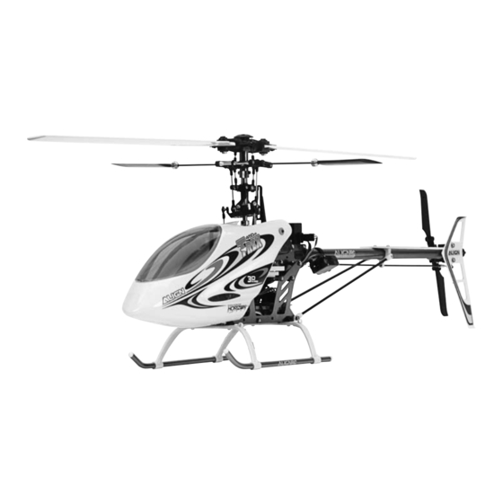
Specifications
Length:
Height:
Main Rotor Diameter:
Tail Rotor Diameter:
Flying Weight:
Main Drive Gear:
Motor Pinion Gears:
Main Gear Ratios:
Main Tail Drive Gear:
Tail Drive Gear:
Tail Gear Ratio:
25.6 in (650mm)
9.0 in (228mm)
27.6 in (700mm)
5.9 in (150mm)
22–24 oz (620–680 g)
150T
11T/13T/15T
13.6:1/11.5:1/10:1
106T
25T
4.2:1
Advertisement
Table of Contents

Related Manuals for Align T-REX 450SA ARF


Summary of Contents for Align T-REX 450SA ARF
-
Page 1: Specifications
Specifications Length: 25.6 in (650mm) Height: 9.0 in (228mm) Main Rotor Diameter: 27.6 in (700mm) Tail Rotor Diameter: 5.9 in (150mm) Flying Weight: 22–24 oz (620–680 g) Main Drive Gear: 150T Motor Pinion Gears: 11T/13T/15T Main Gear Ratios: 13.6:1/11.5:1/10:1 Main Tail Drive Gear: 106T Tail Drive Gear: Tail Gear Ratio: 4.2:1... -
Page 2: Table Of Contents
Table of Contents Introduction ....................3 Electronics Required to Complete . -
Page 3: Introduction
Introduction Welcome to the world of high-performance, electric powered mini helicopters, and thank you for choosing the T-REX 450SA ARF. The T-REX 450SA ARF is based on the proven design and performance of T-REX 450XL and 450SE helicopter models. And through its use of tough, lightweight aluminum and updated composite parts, it offers an excellent blend of performance, durability and reliability of both. For intermediate and advanced pilots, the T-REX 450SA ARF offers performance that rivals even the most capable 90-size glow powered helicopters. Its rapid cyclic response and incredible power loading (when using the recommended power systems) allow it to perform even the most aggressive 3D aerobatics, as well as basic sport and aerobatic flying, with ease. And because the T-REX 450SA ARF is a high-performance, 3D capable model, it is not intended for first- or low-time helicopter pilots. Although the T-REX 450SA ARF arrives 95% factory assembled, please take the time to read through this manual completely before beginning assembly of your model. By carefully following all of the steps outlined here, you can have your 450SA ready to fly in just one or two evenings. -
Page 4: Electronics Required To Complete
T-REX 450SA ARF Contents Before beginning assembly of your T-REX 450SA ARF, carefully remove the airframe, canopy, windshield, decal sheet and bags from the box for inspection. Closely inspect the airframe and parts. If you find any damaged or missing parts, now or during assembly of your model, please contact the place of purchase, email productsupport@horizonhobby.com, or call 1-877-504-0233 toll free to speak to a product support representative. T-REX 450SA Airframe Canopy and Windshield Decal Sheet Cable/Zip Tie and Canopy Mounting Grommet Parts Bag Motor Pinion Gear Parts Bag Motor Mounting Hardware Parts Bag Linkage Parts Bag Servo Mounting Hardware Parts Bag Spare Hardware Parts Bag Hex Wrench and Screw Driver Tool Bag Threadlock and Battery Strap Bag *Actual contents may vary slightly from photos shown Electronics Required to Complete • 6-channel (or greater) transmitter with helicopter and 120-degree CCPM programming • 6-channel (or greater) FM, PCM or Spektrum® DSM® (for use with Spektrum transmitters only) equipped micro receiver • Three sub-micro servos (with at least 17 oz/in of torque) for swashplate (CCPM) control • One sub-micro, micro or mini servo (with a .12 sec/60° or faster transit speed) for tail control • Heading/Tail Lock gyro • 430-class 3150–3550Kv brushless motor • 25-amp (or greater) brushless ESC • 3-cell (11.1V) 2000-2200mAh Li-Po battery pack, capable of 12C (for sport flying only) to 15C... -
Page 5: Recommended Radio Systems And Setups
Recommended Radio Systems and Setups Recommended Radio Systems Spektrum DX6 DSM 6-Channel 2.4GHz Park Flyer System (SPM2460: includes Spektrum AR6000 DSM 6-channel micro receiver and four S75 sub-micro servos) JR® 7202 Synthesized 7-Channel PCM Micro/Mini Heli System (JRP7642: includes JR 790 Synthesized 7-channel PCM micro receiver and three 285 digital sub-micro servos) - Page 6 Sub-Micro S75 Servo 3150Kv w/5V BEC (EFLRS75; four required) (AGNM4360) (AGNE25G) Align 2100mAh 3S 11.1V Li-Po Battery Pack AGNB21003S) Recommended Setup for Sport and 3D Flying Align 500X Head Lock Gyro Align 430L Brushless Motor, Align 35-Amp Brushless ESC E-flite/Spektrum 7.5 Gram...
-
Page 7: Additional Items And Tools Required For Assembly
Align 430L Brushless Motor, (JRPG500T) Servo 3550Kv Servo (JRPS3400G) (AGNM4365) (JRPS285: Three Required) Align 35-Amp Brushless ESC Align 2100mAh 3S 11.1V Li-Po Battery Pack (AGNB21003S) w/5V BEC (AGNE35G) or 6V BEC (AGNE35X) Additional Items and Tools Required for Assembly • Adhesive-Backed Hook and Loop Tape (EFL2135) • #1 Phillips Screwdriver (Optional; EFLA258) • Double-Sided Servo Tape (EFL2135) • #0 Phillips Screwdriver (Optional; EFLA257) -
Page 8: Note On Lithium Polymer Batteries
Warning An RC aircraft is not a toy! If misused, it can cause serious bodily harm and damage to property. Fly only in open areas, preferably at AMA (Academy of Model Aeronautics) approved flying sites, following all instructions included with your radio. Keep loose items that can get entangled in the rotor blades away for the main and tail blades, including loose clothing, or other objects such as pencils and screwdrivers. Especially keep your hands away from the rotor blades. Note on Lithium Polymer Batteries Lithium Polymer batteries are significantly more volatile than alkaline or Ni-Cd/Ni-MH batteries used in RC applications. All manufacturer’s instructions and warnings must be followed closely. Mishandling of Li-Po batteries can result in fire. Always follow the manufacturer’s instructions when disposing of Lithium Polymer batteries. Using the Manual This manual is divided into sections to help make final assembly and preparing for flight easier to understand, and to provide breaks between each major section. Remember to take your time and follow all directions. Limited Warranty Period Horizon Hobby, Inc. guarantees this product to be free from defects in both material and workmanship at the date of purchase. Limited Warranty & Limits of Liability Pursuant to this Limited Warranty, Horizon Hobby, Inc. will, at its option, (i) repair or (ii) replace, any product determined by Horizon Hobby, Inc. to be defective. In the event of a defect, these are your exclusive remedies. This warranty does not cover cosmetic damage or damage due to acts of God, accident, misuse, abuse, negligence, commercial use, or modification of or to any part of the product. This warranty does not cover damage due to improper installation, operation, maintenance, or attempted repair by anyone other than an authorized Horizon Hobby, Inc. service center. This warranty is limited to the original purchaser and is not transferable. In no case shall Horizon Hobby’s liability exceed the original cost of the purchased product and will not cover consequential, incidental or collateral damage. Horizon Hobby, Inc. reserves the right to inspect any and all equipment involved in a warranty claim. Repair or replacement decisions are at the... -
Page 9: Limited Warranty & Limits Of Liability
Limited Warranty & Limits of Liability If you as the purchaser or user are not prepared to accept the liability associated with the use of this product, you are advised to return this product immediately in new and unused condition to the place of purchase. Safety Precautions This is a sophisticated hobby product and not a toy. It must be operated with caution and common sense and requires some basic mechanical ability. Failure to operate this product in a safe and responsible manner could result in injury or damage to the product or other property. This product is not intended for use by children without direct adult supervision. The product manual contains instructions for safety, operation and maintenance. It is essential to read and follow all the instructions and warnings in the manual, prior to assembly, setup or use, in order to operate correctly and avoid damage or injury. Questions, Assistance, and Repairs Your local hobby store and/or place of purchase cannot provide warranty support or repair. Once assembly, setup or use of the product has been started, you must contact Horizon Hobby, Inc. directly. This will enable Horizon to better answer your questions and service you in the event that you may need any assistance. Questions or Assistance For questions or assistance, please direct your email to productsupport@horizonhobby.com, or call 1-877- 504-0233 toll free to speak to a product support representative. Inspection or Repairs If your product needs to be inspected or repaired, pack the product securely using a shipping carton. Please note that original boxes may be included, but are not designed to withstand the rigors of shipping without additional protection. Ship via a carrier that provides tracking and insurance for lost or damaged parcels, as Horizon Hobby, Inc. is not responsible for merchandise until it arrives and is accepted at our facility. Include your complete name, address, phone number where you can be reached during business days, , and a brief summary of the problem. Be sure your name and address are clearly written on the shipping carton. Products requiring inspection or repair should be shipped to the following address (freight prepaid): Horizon Product Support 4105 Fieldstone Road Champaign, Illinois 61822... -
Page 10: Warranty Inspection And Repairs
Warranty Inspection and Repairs To receive warranty service, you must include your original sales receipt verifying the proof-of-purchase date. Providing warranty conditions have been met, your product will be repaired or replaced free of charge. Repair or replacement decisions are at the sole discretion of Horizon Hobby. Non-Warranty Repairs Should your repair not be covered by warranty and the expense exceeds 50% of the retail purchase cost, you will be provided with an estimate advising you of your options. You will be billed for any return freight for non-warranty repairs. Please advise us of your preferred method of payment. Horizon Hobby accepts money orders and cashiers checks, as well as Visa, MasterCard, American Express, and Discover cards. If you choose to pay by credit card, please include your credit card number and expiration date. Any repair left unpaid or unclaimed after 90 days will be considered abandoned and will be disposed of accordingly. Safety, Precautions, and Warnings As the user of this product, you are solely responsible for operating it in a manner that does not endanger yourself and others or result in damage to the product or the property of others. This model is controlled by a radio signal that is subject to interference from many sources outside your control. This interference can cause momentary loss of control so it is advisable to always keep a safe distance in all directions around your model, as this margin will help to avoid collisions or injury. • Never operate your model with low transmitter batteries. • Always operate your model in an open area away from cars, traffic, or people. • Avoid operating your model in the street where injury or damage can occur. • Never operate the model out into the street or populated areas for any reason. • Carefully follow the directions and warnings for this and any optional support equipment (chargers, rechargeable battery packs, etc.) that you use. • Keep all chemicals, small parts and anything electrical out of the reach of children. • Moisture causes damage to electronics. Avoid water exposure to all equipment not specifically designed and protected for this purpose. -
Page 11: Swashplate Servo Installation
1.0 Swashplate Servo Installation Three sub-micro servos (with at least 17 oz/in of torque) are required for swashplate (CCPM) control. 1.1 Using a 1.5mm hex wrench, remove the aluminum frame joiner located just above the forward servo mount holes as shown. This will allow the pitch and aileron servo to be installed more easily. 1.2 Remove the servo arm and screw from each servo and set them aside. 1.3 Install the pitch servo inside the lower forward hole in the right-hand frame as shown. Note that the output shaft of the servo must be oriented toward the rear of the helicopter. - Page 12 1.4 Using the hardware included in the Servo Mounting Hardware Parts Bag, fasten the servo in place with two screws and two servo mounting plates. Note that the servo mounting plates have an extended portion on one side. When using JR servos, the extended portion of the servo mounting plate fits inside the servo’s mounting tab to help precisely center the servo in the frame. When using other types of servos, the flat side of the servo mounting plate rests against the servo mounting tab.
- Page 13 1.5 Next, install the aileron servo inside the upper forward hole in the left-hand frame as shown. Note that the output shaft of the servo must be oriented toward the rear of the helicopter. Use two screws and two servo mounting plates to fasten the aileron servo in place. 1.6 The elevator servo mounts outside of the rear hole in the left-hand frame. The output shaft must be facing inside the frame, oriented toward the rear of the helicopter. Note that the elevator servo’s lead must pass though the frame, in the notch provided just below the servo, before the servo is installed.
- Page 14 1.7 Use two screws and two servo mounting plates to fasten the elevator servo in place. The screws are installed from inside the frame, with the servo mounting plate on the outside of the servo mounting tab.
- Page 15 1.8 Reinstall the aluminum frame joiner using the green colored R48 threadlock provided. 1.9 Carefully route the servo wire leads down the inside of the upper right main frame and out the rear of the model just ahead of the tail boom mount. Secure them to the frame using cable/zip ties and the slots found just behind the pitch servo and ahead of the tail boom mount.
-
Page 16: Tail Servo Installation
2.0 Tail Servo Installation One sub-micro, micro or mini servo (with a .12 sec/60° or faster transit speed) is required for tail control. 2.1 Install the tail rotor servo on the tail boom servo mounts using two of the remaining servo mounting screws. If you are installing the JR 3400G servo, be sure to also use two of the blue anodized aluminum cap washers from the Spare Hardware Parts Bag. Note that the output shaft of the servo must be oriented toward the rear of the helicopter. 2.2 Leave the tail boom servo mounts loose on the boom at this time, as the servo and mount positions will be adjusted later on. -
Page 17: Gyro Installation
3.0 Gyro Installation A heading/tail lock gyro is required for the best possible tail holding performance. We recommend that the gyro be mounted on the main frame base plate, just ahead of the motor mounting area and below the battery mounting plate. This position offers good crash protection for the gyro, and helps to better balance the helicopter. Note: If you are using the Align 500X gyro, a short (approximately 3-6”) servo extension may be required when connecting the tail servo to the gyro in this location. - Page 18 Another option for mounting the gyro is to secure the gyro on top of the tail boom holder, near the rear of the upper main frame. 3.1 Thoroughly clean the base of the gyro and the area that the gyro will be mounted on with isopropyl alcohol. 3.2 Using the double-sided tape provided with the gyro, or servo tape, mount the gyro in your chosen position.
-
Page 19: R Eceiver Installationand Connection
4.0 Receiver Installation and Connection A 6-channel (or greater) micro receiver is required. We recommend the use of a PCM receiver (like the JR 790) if using a 72MHz transmitter. However, for the ultimate in glitch-free performance, we strongly recommend the use of a DSM (Digital Spectrum Modulation) equipped receiver (like the Spektrum AR6000) and transmitter on 2.4GHz. The Spektrum DX6 transmitter and AR6000 receiver system has become a favorite among T-REX 450 pilots due to its robust and reliable RF link that makes glitching and range impairment from motor, ESC, servo and mechanical RF “noise” a thing of the past. It also eliminates any issues related to operating on 72MHz, as you will no longer need to worry about securing an open channel, or having someone accidentally “turn on” on your channel while flying, potentially causing loss of control and a crash. - Page 20 4.1 Mount the receiver on top of the main frame base plate, near the rear of the lower main frames. Use double-sided tape and a cable/zip tie to fasten it in position.
- Page 21 4.2 If using a Spektrum AR6000 receiver, route the antennas down the inside of each rear landing gear strut and secure them in place with clear tape. If using a 72MHz receiver, route the antenna out the side of the model, then into and out of the antenna tube installed in the landing gear strut holders. It is extremely important to be sure that the antenna does not pass near any electronic components, and that it is secured to prevent it from coming into contact with any moving parts (especially the rotor blades). If using a 72MHz receiver, you may also choose to install a base-loaded antenna to help reduce the length of the antenna required for proper operation. We suggest using a Revolution Base-Loaded Whip Antenna (RVO1010) as it can easily be mounted securely in the landing gear strut holders.
- Page 22 4.3 Once you have completed installation of the receiver and antenna, it will be necessary to connect the gyro and servos to the receiver for radio system setup later on. Please see the lists and illustrations below, while also referring to the manuals for your transmitter and gyro, for proper connections. For JR and Spektrum Transmitters/Receivers Channel 1 (THRO) ESC ‘throttle’ lead (will be connected later on) Channel 2 (AILE) Left-hand forward ‘aileron’ servo lead Channel 3 (ELEV) Rear ‘elevator’ servo lead Channel 4 (RUDD) Gyro ‘rudder’ lead Channel 5 (GEAR) Gyro ‘auxiliary’ lead (optional) Channel 6 (AUX1) Right-hand forward ‘pitch’ servo lead JR and Spektrum Receiver Connections Throttle (CH1) Aileron (CH2) 6-Channel Receiver Elevator (CH3) Rudder (CH4) Gyro Gear (CH5) Gyro Aux (Optional) Pitch...
- Page 23 For Futaba and Hitec Transmitters/Receivers Channel 1 (AILE) Left-hand forward ‘aileron’ servo lead Channel 2 (ELEV) Rear ‘elevator’ servo lead Channel 3 (THRO) ESC ‘throttle’ lead (will be connected later on) Channel 4 (RUDD) Gyro ‘rudder’ lead Channel 5 (GEAR) Gyro ‘auxiliary’ lead (optional) Channel 6 (AUX1) Right-hand forward ‘pitch’ servo lead Futaba and Hitec Receiver Connections Aileron (CH1) Elevator (CH2) 6-Channel Receiver Throttle (CH3) Gyro Rudder (CH4) Gear (CH5) Gyro Aux (Optional) Pitch...
-
Page 24: Preparing The Motor And Electronic Speed Control For Installation
5.0 Preparing the Motor and Electronic Speed Control for Installation A 430-class 3150–3550Kv brushless motor and 25-amp (or greater) brushless electronic speed control (ESC) are required for the best performance. Depending on the motor and ESC you have chosen to use, it may be necessary for you to install connectors for connecting the motor to the ESC, and the battery to the ESC. Please check to see if your motor and ESC include connectors. If they do not, we recommend use of the following: For Connecting the Motor to the ESC: Align Gold Bullet Connector/Terminal Set, 3.0mm (AGNA240)* E-flite Gold Bullet Connector Set, 3.5mm (EFLA241) *Typically included with Align 430L brushless motors For Connecting the Battery to the ESC: E-flite EC3 DEVice Connector, Male (2) (EFLAEC301)* E-flite EC3 BATTery Connector, Female (2) (EFLAEC302)** E-flite EC3 DEVice & BATTery Connector, Male/Female (EFLAEC303) *Typically included with Align brushless ESCs **Typically included with Align Li-Po battery packs 5.1 If your motor and ESC do not include installed connectors, use a soldering iron and solder to install them per the manufacturer’s recommendations. Be sure to insulate the connectors properly using... -
Page 25: Motor Installation
6.0 Motor Installation Your kit includes 11-tooth (one each with 2.3mm and 3.17mm inner diameters), 13-tooth (3.17mm ID) and 15-tooth (3.17mm ID) motor pinion gears. If using the Align 430L 3150Kv or 3550Kv motor, we recommend use of the 13-tooth pinion for the best overall power and duration. If another motor will be used, please consult the manual and/or manufacturer of the motor to find the recommended pinion gear tooth count to use. 6.1 Install the pinion gear on the motor shaft using the setscrew included in the Motor Pinion Gear Parts Bag and a small amount of green colored R48 threadlock. Only lightly tighten the setscrew at this time, as the final position of the pinion on the shaft will be adjusted after the motor is installed. 6.2 Locate the Motor Mounting Hardware Parts Bag. Note that two sizes of screws and washers are included in the bag (hex and Phillips head 2.5mm, and Phillips head 3.0mm). Also note that there are two sizes of mounting holes in the Align 430L motor, allowing either 2.5 or 3.0mm screws to be used. We recommend using the 2.5mm screws, as they will not require you to widen the slots in the motor mount. If using a motor other than the Align 430L, be sure to choose the size of screw that fits the motor’s mounting holes correctly. It is typically best to consult the manual and/or manufacturer of the motor to find the correct size. 6.3 Place the motor in position and align the mounting holes you have chosen to use with the slots in the motor mount. Install the screws and washers and tighten them lightly to allow the gear mesh to be adjusted. Do not work to set the gear mesh correctly at this time as the pinion gear location on the motor shaft must be set properly first. - Page 26 6.4 Viewing the model from the side, note the height of the pinion gear on the motor shaft in relationship to the main gear. The top of the pinion gear should be set slightly (about 1/32”) above the main gear. Loosen the pinion’s setscrew and adjust the pinion height as necessary until it is correct. Then, securely tighten the setscrew. 6.5 Loosen the motor mounting screws just enough to allow adjustment of the pinion gear/main gear mesh by moving the motor fore and aft on the motor mount. When the gear mesh is adjusted correctly, there should be a very slight amount of play present between the gears. Once you have set the gear mesh correctly, tighten the motor mounting screws securely. Note: It is very important to set the gear mesh so that it is smooth with no binding. Be certain to check the mesh at multiple points on the main gear in order to find the position in which to secure the motor for the best gear mesh overall.
-
Page 27: Electronic Speed Control Installation
7.0 Electronic Speed Control Installation Depending on the receiver and electronic speed control (ESC) you have chosen to use, there are several possible locations for the ESC on your model. If using a 72MHz receiver, we recommend mounting the ESC on the bottom of the main frame base plate with the heat sink or power FETs (if no heat sink is used) facing downward. This helps to keep the ESC farther away from the receiver to help prevent possible interference it may cause. If using a 2.4GHz Spektrum AR6000 receiver, we recommend mounting the ESC on top of the main frame base plate, below the main gear, with the heat sink facing upward. Note, this may require you to adjust the position of the receiver so that it can rest partially on the end of the ESC where the motor wire leads exit. Because the main and tail drive gears are designed to act as cooling fans, they can move additional air across the ESC’s heat sink for cooler operation when in this location. And, because the AR6000 receiver is being used, there is no need to worry of possible interference the ESC may cause when mounted this close to 72MHz receivers. - Page 28 7.1 After choosing a position for mounting the ESC, fasten it in place using double-sided servo tape and cable/zip ties. Note that slots are located in the base plate to allow the cable/zip tie to neatly fasten the ESC in position. 7.2 Secure the battery power input and motor power output wire leads exiting the ESC to prevent them from coming into contact with any moving parts. 7.3 Connect the ESC’s throttle channel servo lead to the throttle channel on your receiver. Be sure to secure this lead so that it cannot come into contact with any moving parts. 7.4 Do not connect the ESC’s motor power output wire leads/connectors to the motor at this time as it will be necessary to set up the servos by using the ESC for power. This is only safe to accomplish with the motor disconnected.
-
Page 29: Initial Transmitter Setup And Adjustment
8.0 Initial Transmitter Setup and Adjustment Before proceeding with servo arm setup and installation, it is important to ensure that the initial transmitter settings are correct so that the servos are responding properly to control inputs and adjustments. The following are required settings for all JR and Spektrum transmitters. These settings will also be similar for other brands of transmitters. Type Select Helicopter Servo Reversing for E-flite®/Spektrum S75 Servos Throttle Normal (Reversed for Futaba or Hitec transmitter) Aileron Normal (Reversed for JR or Hitec servo) Elevator Normal (Normal for JR or Hitec servo) Rudder Normal (Reversed for JR or Hitec servo) Gear Normal Pitch Reversed (Normal for JR or Hitec servo) CCPM Setting and Travel Values for E-flite/Spektrum S75 Servos Set to 3 servos, 120°... -
Page 30: Servo Arm Setup And Installation
9.0 Servo Arm Setup and Installation With the motor disconnected from the ESC for safety, power on your transmitter and plug a charged battery into the ESC to provide power to the servos, gyro and receiver. 9.1 Set the swashplate (CCPM) servos to their neutral position by exactly centering the throttle/ collective stick. If your transmitter features a graphic display of pitch curves, it may be helpful to select this menu to better determine the exact mid-stick position. If your transmitter does not feature a graphic display, you can also set the low and high point pitch curve values to 50% (so they are the same as the midpoint pitch curve value), so that no matter where the throttle/collective stick is positioned, the servos will remain in their neutral position. However, you must be sure to re-adjust the low and high point pitch curve values after installing the servo arms to check for proper operation and for proper flight performance. 9.2 With the swashplate (CCPM) servos in their neutral position, you will need to find servo arms, that when installed on each servo, are as close to level (horizontal) as possible. Note, if you are using E-flite/Spektrum S75 servos, you will want to find servo arms that are angled approximately 5–10° upward when installed with the servos in their neutral position. - Page 31 For JR 285 Servos Use the longest side of the four-sided arm with the control ball placed in the mounting hole 12.5mm from the center. For Hitec HS-65 Servos Use the two-sided arm with the control ball placed in the mounting hole 15.0mm from the center. 9.3 Set the gyro to Standard Rate Mode (non-heading/tail lock mode; see the gyro manual for more info) and center the rudder stick. The tail servo should be in the neutral position. If you are unsure of whether your gyro is in the standard rate mode, or if it does not offer a feature that allows it to be used in a standard rate mode, you can disconnect the gyro from the receiver and plug the tail servo directly into the rudder channel.
- Page 32 9.4 With the tail servo in its neutral position, you will need to find a servo arm that, when installed on the servo, is as close to perpendicular to the tail boom as possible. Be sure to test multiple arms and arm positions (for example, if it is a two-sided arm, try both sides) on the servo to find an arm that matches the intended position closest. Please see the following photos and notes to help you select the correct servo arm for your chosen servo, and the location in which the tail rotor pushrod linkage Z-bend should be placed. Be sure to enlarge the mounting hole using a sharp hobby knife (if required) to provide smooth movement of the Z-bend in the mounting hole, with no additional slop or free play. Also, be sure to remove any unused portions of the servo arm to prevent binding: For E-flite/Spektrum S75 Servo Use the single-sided arm with the Z-bend placed in the mounting hole 7.0mm from the center. For JR 3400G Servo Use a shorter side of the four-sided arm with the Z-bend placed in the mounting hole 8.0mm from the center.
- Page 33 For Hitec HS-65 Servo Use the two-sided arm with the Z-bend placed in the hole 7.5mm from center. 9.5 With the tail rotor pushrod linkage Z-bend and servo arm installed, it will be necessary for you to adjust the position of the servo and tail boom servo mounts to provide proper alignment of the pushrod and tail pitch slider. First, adjust the servo and tail boom servo mounts (by rotating them around the boom) until the pushrod is running as straight as possible through the support and to the control ball on the tail pitch control lever. Then, adjust the servo and tail boom servo mounts (by sliding them fore or aft on the boom) until the tail pitch slider is centered on the tail rotor shaft. When the slider is centered, the ends of the brass bushing should be at equal distances from the tail rotor case and tail rotor hub. 9.6 After confirming that the tail rotor pushrod and tail pitch slider are properly aligned, secure the tail boom servo mounts to the boom by tightening the screws that close the clamp. Be careful, however, as tightening the screws too much can cause the mounts to snap. The mounts should only be tight enough to prevent them from moving under moderate amounts of hand pressure. 9.7 Be sure to re-install the servo arm mounting screw in each servo before proceeding.
-
Page 34: Control Linkage Assembly, Installation And Adjustment
10.0 Control Linkage Assembly, Installation and Adjustment Proper assembly, installation and adjustment of the control linkages is critical to the flight performance of your model. When assembling the control linkages, we recommend the use of vise grips or needle-nose pliers for holding the pushrod while installing the plastic ball links. We also recommend the use of a metric ruler or calipers to set the proper length of each linkage as listed. Three dimensions are given for assembly of each control linkage required: • Length of pushrod used (Rod Length) • Completed length from ball center to ball center of each link (C to C Length) • Completed length from outside to outside of each link (Overall Length; easiest length to use for reference when checking with a ruler or calipers) C to C Length Rod Length Overall Length 10.1 Remove the pushrods and ball links from the Linkage Parts Bag and assemble them as follows: A) Main blade grip to mixing arm linkages, two required: Rod Length 9.0mm C to C Length 20.0mm... - Page 35 F) Aileron servo (front left) arm to outer swashplate, one required: Rod Length 19.0mm C to C Length 32.3mm Overall Length 37.8mm 10.2 Install the completed linkages as shown in the following photos. Note, the side of the plastic ball link marked with an “A” should be facing away from the control ball when installed properly. Also note that some of the linkages may require one of the ball links to be adjusted perpendicular or slightly angled to the other for proper alignment (this should already be the case if you have assembled the linkages to the lengths previously listed, however, make any adjustments to the ball links for proper alignment as necessary). Note: When installing the elevator linkage on the outer swashplate, it is best to remove the screw and control ball with anti-rotation post from the swashplate and anti-rotation bracket first.
- Page 36 10.3 After installing the linkages, check the fit of each ball link on the control ball. Ideally the link will fit the ball securely and move freely, with no additional play on the ball. If any of the links fit the balls tight enough that they are difficult to twist by hand and do not move freely, we suggest adjusting the fit of the link so that it moves more freely on the ball. Ball links that fit the control balls too tightly can cause difficulties in control and accelerated servo wear. We recommend the use of an adjustable Ball Link Sizing Tool (JRP960219) as it will allow you to adjust each link for a precision fit on the ball. Also, we strongly recommend the use of Ball Link Pliers (KSJ673) to help remove ball links from the control balls without causing damage to the link. If you find any ball links that do not fit the control balls securely, replace them immediately with new links from the Spare Hardware Parts Bag. Links that are not secure can disconnect from the balls in flight, causing a loss of control and possibly a crash.
-
Page 37: Additional Transmitter Setup And Adjustment
11.0 Additional Transmitter Setup and Adjustment After installing the control linkages, it will be necessary for you to set and adjust the following in your transmitter before proceeding with testing the controls for proper response and operation. The following are required settings for all JR and Spektrum transmitters. These settings will also be similar for other brands of transmitters. Sub-Trim Throttle Aileron M inimum required so servo arm is horizontal (or 5–10° upward if using an S75 servo) at half stick/0° pitch Elevator M inimum required so servo arm is horizontal (or 5–10° upward if using an S75 servo) at half stick/0° pitch Rudder M inimum required to trim tail servo neutral in Heading/Tail Lock Mode (See gyro manual for more info) Gear Pitch M inimum required so servo arm is horizontal (or 5–10° upward if using an S75 servo) at half stick/0° pitch Travel Adjustment Values Throttle -100% / +100% Aileron -100% / +100% Elevator -100% / +100% Rudder - 80% / +80% (Adjusted to control tail servo response and speed of pirouette after flight testing. See gyro manual for more info.) Gear - 75% / +75% (Adjusted to control gyro gain value after flight testing. -
Page 38: Control Tests
12.0 Control Tests Once you have completed the additional setup of your transmitter, you will be able to test the controls for proper response and operation. As long as you have followed the recommendations for servo and control linkage set up and installation, and used the recommended transmitter settings, no adjustments should be required. 12.1 First, power on your transmitter. Then, plug a charged battery pack into the ESC. Note: The motor must be disconnected from the ESC to perform the control test safely (it will be connected to the ESC later on). 12.2 To test the swashplate (CCPM) controls, position the helicopter to view it from the left or right side. Move the left-hand stick up and down to check collective pitch control. When the stick is pushed up, the swashplate should raise, increasing the pitch of the main blades. With the stick pulled back down, the swashplate should lower, decreasing the pitch of the main blades. ... - Page 39 Again viewing the helicopter from the left or right side, move the right-hand stick forward and aft to check elevator pitch control. When the stick is pushed forward, the swashplate should also tilt forward. With the stick pulled back, the swashplate should tilt toward the rear. ...
- Page 40 Viewing the helicopter from the rear (tail boom toward you), move the right-hand stick left and right to check aileron roll control. When the stick is pushed to the left, the swashplate should also tilt left. With the stick pushed right, the swashplate should tilt to the right. If at any time during the test the swashplate (CCPM) controls do not respond properly, double-check the servo reversing setting for each servo, and the CCPM travel values/direction for each function. Remember that: Changing the servo reversing setting for a given servo will reverse its operation. Changing the CCPM travel value for a given function (for example, from -65% to +65%) will reverse its operation. Please see the manual included with your transmitter for more information.
- Page 41 12.3 To test tail control, it is usually helpful to set the gyro to Standard Rate Mode (non-heading/tail lock mode). If you are unsure of whether your gyro is in the standard rate mode, or if it does not offer a feature that allows it to be used in a standard rate mode, you can disconnect the gyro from the receiver and plug the tail servo directly into the rudder channel on your receiver. Then, position the helicopter to view the tail pitch slider from above, with the tail boom pointed toward you. Move the left-hand stick left and right to check rudder yaw control. When the stick is pushed to the left, the tail pitch slider should move to the right, toward the tail rotor hub. With the stick pushed to the right, the tail pitch slider should move to the left, toward the tail case. If you find that the tail servo is responding opposite to rudder control inputs, simply reverse the rudder channel in your transmitter.
- Page 42 12.4 To test gyro control and response, it is usually helpful to watch the tail servo arm for reference. While observing the tail servo arm, give a right rudder input on the transmitter. Note the direction that the servo arm moves. Then, move the nose of the helicopter quickly to the left while still observing the tail servo arm (it may take a few attempts to observe the tail servo arm movement properly). If the servo arm moves in the same direction as it did when you gave the right rudder input before, then the gyro is responding properly by attempting to counteract the left-hand movement of the nose with a right rudder input. If, however, the tail servo arm is moving opposite the direction it did when you gave the right rudder input before (for example, offering a left rudder input when you move the nose of the helicopter quickly to the left, further exaggerating the effect rather than counteracting it), you will need to use the Reverse switch located on the gyro to reverse the direction of response. Please see the gyro manual for more information if required.
-
Page 43: Throttle And Pitch Curve Settings And Adjustments
13.0 Throttle and Pitch Curve Settings and Adjustments Before completing assembly of your new model and conducting the first flight, it will be necessary for you to complete setup of the throttle and pitch curves. The following settings allow for typical hovering and forward flight in Normal Flight Mode, and sport, aerobatic or 3D flying in the Idle Up/Stunt (3D) Flight Mode. 13.1 First, set the throttle curve values in your transmitter as follows: Throttle Curve Values High Normal 0% (TLN) 80% (T2N) 100% (THN) Idle Up/Stunt 100% (TLS) 85% (T2S) 100% (TLS) 13.2 Next, set the pitch curve values in your transmitter as follows: Pitch Curve Values High Normal 35% (PLN) 50% (P2N) 95% (PHN) Idle Up/Stunt 5% (PLS) 50% (P2S) 95% (PHS) Hold 5% (PLH) 50% (P2H) - Page 44 If you find that both rotor blades are not positioned at exactly 0° of pitch, are certain that you have assembled and adjusted all linkages to the recommended lengths and have the servos in their neutral position, we suggest adjusting the lengths of the servo-to-swashplate (D, E, F) linkages. You will need to shorten the length of all three servo-to-swashplate linkages by an equal amount if the rotor blades are set to positive pitch, and vice-versa if the rotor blades are set to negative pitch. Make small adjustments to the length of all three linkages in equal amounts until the rotor blades are positioned at exactly 0° of pitch. Note: If you are using E-flite/Spektrum S75 servos, you will need to shorten the lengths of the servo-to-swashplate linkages in order to achieve exactly 0° of pitch for the main rotor blades. Again, you must shorten the length of all three linkages by an equal amount, and the amount of adjustment required will vary slightly depending on the actual neutral position of the servo arms (which can be between approximately 5°...
- Page 45 First, confirm that the main rotor blades are positioned at 0° of pitch with the throttle/collective stick in exactly the center position, when in the Idle Up/Stunt Flight Mode. Then, confirm that the main rotor blades are positioned at approximately +9° to +11° with the throttle/collective stick in its highest position. If they are not, adjust the Idle Up/Stunt Flight Mode High pitch curve value (PHS), or the Pitch CCPM travel value (CP6), as required. Finally, check to see that the main rotor blades are positioned at approximately -9° to -11° with the throttle/collective stick in its lowest position. As long as the Idle Up/Stunt Flight Mode Low pitch curve value (PLS) corresponds exactly to the Idle Up/Stunt Flight Mode High pitch curve value (PHS; For example, 5% PLS corresponds exactly to 95% PHS, and 0% PLS corresponds exactly to 100% PHS, etc), the main rotor blades should be positioned at the same amount of pitch in opposite directions (for example, -10° at low stick and +10° at high stick). -9~-11˚ Typically, we find that approximately -/+10° of pitch is a very good starting point for most pilots when at low and high stick positions in the Idle Up/Stunt Flight Mode. 13.8 Note, some minor adjustments of the throttle and pitch curves may be required after making the first and subsequent flights. This usually depends most on personal preference and/or flying style of the pilot, as well as the performance of the power system and main rotor blades used. 13.9 Now that you have completed setup of your model, power down the transmitter and helicopter and proceed with final assembly.
-
Page 46: Canopy And Windshield Assembly And Installation
14.0 Canopy and Windshield Assembly and Installation 14.1 Use Scissors (DYN2511) and/or a sharp Hobby Knife (EXL16001) to carefully remove plastic from the back, windshield area and vent holes on the side/bottom of the canopy on the molded cut lines. You will also need to remove the plastic along the molded cut line around the windshield. 14.2 Use clear tape or small self-tapping screws from the Spare Hardware Parts Bag to fasten the windshield to the canopy. 14.3 Insert the canopy mounting grommets (found in the Cable/Zip Tie and Canopy Mounting Grommet Parts Bag) in the holes on each side of the canopy. 14.4 Apply the included decals on the canopy, horizontal and vertical fins using the images found on the box for reference. 14.5 The canopy is installed on the model by first placing its bottom under the forward extending “ledge” of the main frame base plate. Then, place the grommets onto the canopy mounts found just behind the main shaft and near the top of the upper frames. Note: If you find that any of the control linkages bind against the canopy once it is installed, be sure to remove additional plastic material from the canopy until the binding no longer occurs. -
Page 47: Battery Mounting And Center Of Gravity Check
15.0 Battery Mounting and Center of Gravity Check It is extremely important to mount the Li-Po battery pack securely in your model, while also achieving the proper center of gravity. 15.1 Place a section of Adhesive Backed Hook and Loop Tape (EFL2135) on the battery mounting plate and battery pack. We recommend using the “hook” material on the mounting plate, and the “loop” (fuzzy) material on the battery pack. 15.2 Mount the battery pack on the mounting plate and install the canopy. Lift the helicopter by the flybar with the flybar positioned perpendicular to the tail boom. The model is balanced correctly if it is in a level position in relation to the ground. If, however, the nose or tail are at a slight downward angle, adjust the position of the battery pack on the mounting plate forward or rearward as required (with the canopy removed) and repeat the center of gravity check (with the canopy installed). Continue the battery position adjustments and CG checks until the model holds a level position when balanced on the flybar. - Page 48 15.3 Once you have confirmed the mounting position of the battery pack that achieves the correct CG, remove the canopy and install the hook and loop strap (found in the Threadlock and Battery Strap Bag) around the battery pack and mounting plate for added security. Note, if you do not install the hook and loop strap, it is still possible for the battery to come loose in flight during aggressive aerobatic maneuvers. Be sure to install the hook and loop strap and to check the CG of your model before each flight, especially if you are switching between different sizes and types of battery packs.
-
Page 49: Setting Tail Rotor Drive Belt Tension
16.0 Setting Tail Rotor Drive Belt Tension Proper tail drive belt tension plays a critical role in achieving maximum performance and reliability of your model. If the belt tension is set too tight, power can be lost while also causing the belt and/or pulleys to wear more quickly. If the belt tension is set too loose, the belt can skip and strip teeth from the belt and pulleys, while also potentially causing a loss in tail power and control in flight. 16.1 Position the helicopter to view the tail drive belt and forward drive pulley from above. Standard Belt Tension Guide: Visualize a straight line through the center of the forward tail drive pulley. You should be able to apply light tension to the belt with your finger until it reaches a point 3/4 of the way to the opposite side of the belt, or 1/4 of the way past the virtual center of the forward... -
Page 50: Motor Connection And Test
17.0 Motor Connection and Test Now that you have completed assembly and setup of your model, it will be necessary for you to connect the motor to the ESC to test its operation. 17.1 First, remove the main rotor blades, mounting bolts and nuts from the main rotor blade grips. This will allow you to test the motor’s operation more safely. 17.2 Connect the three motor wire leads to the motor power output leads of the ESC. You can connect the wire leads in any order. 17.3 Move your model (with battery pack installed but not connected) and transmitter to an open area. This will allow you to power up the model to confirm that the motor is both operating correctly, and rotating in the correct direction. 17.4 Turn your transmitter on first, with the throttle/collective stick in its lowest position. Then, plug the battery pack into the ESC. Be sure to exercise extreme caution as the ESC may now be armed, which could allow the motor to spin the flybar/flybar paddles and tail rotor blades. 17.5 Carefully move clear of the model, flybar paddles and tail rotor blades. Also, be sure that no loose articles or other obstructions can come into contact with the flybar paddles and tail rotor blades. Once clear of the model and any moving parts, and certain the ESC has been armed properly (see ESC manual for more info if required), slowly advance the throttle/collective stick until the motor begins to spin. 17.6 Note the direction that the flybar paddles spin with the motor running. They should spin clockwise when viewing the helicopter (at a safe distance) from above. If the flybar paddles are spinning clockwise, the motor is operating in the correct direction. If, however, the flybar paddles are spinning counterclockwise, the motor is operating in the wrong direction. Power the model down (stop the motor and unplug the battery pack) and reverse the positions of any two motor wire lead connections to the ESC. Then, repeat the steps to check the direction the flybar paddles spin with the motor running. They should now be spinning clockwise, indicating that the motor is operating in the correct direction. -
Page 51: Main Rotor Blade Balancing
18.0 Main Rotor Blade Balancing Proper main rotor blade balance is critical to the flight performance of any helicopter model. Although the main rotor blades included with your model have been carefully selected and matched by weight, we recommend checking their balance before the first flight by using a Blade Balancer (KSJ1470). 18.1 If you find that the blades are not balanced, add a section of the included red or blue Tracking Tape near the tip of the lighter (higher) blade. Check the balance again, and add or remove tape as necessary until the blades are balanced (level on the balancer). - Page 52 18.2 After balancing the rotor blades, and before reinstalling them in the blade grips, check the security of the bolts that mount the blade grips and bearings to the feathering/spindle shaft. This will require the use of two 1.5mm hex drivers, one on each side. 18.3 After confirming that the bolts are secure, reinstall the main rotor blades, mounting bolts and nuts in the blade grips. The bolts for securing the blades should be tightened so that the blades can pivot in the grips when moderate pressure is applied. Never allow the main blades to swing freely in their grips.
-
Page 53: Before The First Flight
19.0 Before the First Flight • Take your time to check the security of all screws on your model. Tighten any screws that may be loose, and replace any screws or parts that may have been stripped during assembly. • Check to be sure that all electronic equipment and wire leads are secure and will not come into contact with any moving parts. • Check to be sure that the flybar paddles are parallel to the flybar control frame and one another. • Apply a small amount of lightweight oil (TRI4026) on the main shaft where the swashplate ball and washout base bushing travel. • Check to be sure that the bolts for securing the tail rotor blades in the tail rotor blade grips are tightened so that the blades can pivot in the grips when moderate pressure is applied. • Apply a small amount of lightweight oil (TRI4026) on the tail rotor shaft where the tail pitch slider bushing travels. • Make sure that your ESC is programmed to the correct settings for use in the helicopter with your chosen motor and battery pack (See the ESC manual for more info). • Check to be sure that the swashplate, washout, servo arms and all other related parts do not bind with maximum control inputs. If you experienced any binding, adjust the length of the linkages, individual servo travel values and/or CCPM travel values to prevent this. • Take the time to have an experienced helicopter pilot check the assembly and setup of the model. -
Page 54: Main Rotor Blade Tracking
20.0 Main Rotor Blade Tracking You can check tracking of the main rotor blades before or during the first flight of your model. When doing so, be sure to maintain a safe distance from the helicopter (approximately 15–20 feet). We also suggest having an assistant on hand to help sight the blades, especially if you will be flying the model. 20.1 Bring the main rotor blades up to speed. If both blades are running in the same plane, no adjustments will be required. If, however, the blades are not tracking in the same plane, adjustment will be necessary. 20.2 If you find that the main rotor blades are out of track, note which blade is running low and which blade is running high (by using colored tracking tape on one or both blades). Then, power the model down and adjust the linkages to raise the low blade, or lower the high blade (depending on your desired pitch curves). Use the main blade grip to mixing arm linkage (A) for adjusting larger variations in tracking, or the mixing arm to inner swashplate linkage (C) for adjusting smaller variations in tracking. Blades Out Of Track - Adjustment Necessary Colored Tracking Tape Linkage A Linkage C 20.3 Continue to check the blade tracking and adjust the linkages as required until both blades are running in the same plane. Typically, not much adjustment should be required. However, if significant adjustments of the linkages are required to obtain proper blade tracking, double-check the lengths of the pitch control linkages (they should be close to the same length) and if the rotor blades have any warps or twists. Blades In Track - No Adjustment Necessary... -
Page 55: Recommended Maintenance
21.0 Recommended Maintenance Routine maintenance is necessary to keep your T-REX 450SA in optimal and safe flying condition. Ball Links Before each flying session, check to see that the ball links are secure, but not tight (binding), on the control balls. The plastic ball links can wear over time, and if they become too loose on the control balls, they can separate from the ball in flight and cause a crash. The ball links on the inner swashplate are especially subject to high wear, and it’s important to check these often. Subjected to hard 3D flying, these links can become loose in about 40 to 50 flights. Be sure to replace any worn ball links before they fail. O-Ring Head Dampeners The O-ring dampeners in the head block can periodically wear and lose their elasticity. Worn O-rings can cause main rotor blade tracking problems. If you start having trouble with the blades going in and out of track during flight, it is likely time to replace the O-ring dampeners. When replacing the O-ring dampeners it’s important to lubricate them with grease or Vaseline to prevent friction. Aggressive 3D flight can wear out the O-ring dampeners in the head in approximately 50 to 80 flights. Tail Rotor Drive Belt It’s typical for the tail drive belt to stretch slightly over the first 20 flights. When new, frequently check and adjust the belt tension as required. After approximately 30 to 40 flights, the belt elasticity will stabilize, requiring little to no additional tension adjustment. Bearings The one way bearing in the main drive gear should be cleaned using isopropyl alcohol or electric motor spray, then lubed with lightweight oil, approximately every 100 flights. All other bearings typically exhibit very long life and normally only need to be replaced if they ever become notchy (sticky in places when turning) or draggy. 22.0 After Crash Inspection After a crash, no matter how major or minor, it’s vital to carefully check for and replace any damaged parts. Pay special attention to the main and tail rotor blades, blade grips, the feathering/spindle shaft, main shaft and tail rotor shaft. Also, be sure to check the tail rotor drive belt, all drive and servo gears, for damaged or missing teeth. If you have even the slightest doubt about the integrity of a part, it must be replaced. -
Page 56: Main Rotor Head Assembly Parts Listing
Main Rotor Head Assembly Parts Listing Exploded View Included Reference Quantity In Item Number Description Size Required Number Aluminum Rotor Housing/Head Block AGHN1213G Head Stopper/Button AGNH1113 Socket Button Head Screw M2x6mm AGNH1150 Guide Pin AGNH1113 O-Ring Head Dampener AGNH1166 Aluminum Spacer 3x5x1.5mm AGNH1114 Stainless Steel Linkage/Control Ball AGNH1227 Countersunk Screw M2x6.5mm AGNH1227 Main Rotor Holder/Grip AGNH1114 Bearing 3x8x4mm AGNH1154 Bearing... -
Page 57: Main Rotor Head Assembly Exploded View
Main Rotor Head Assembly Exploded View... -
Page 58: Washout, Swashplate And Main Drive Gear Assemblies Parts Listing
Washout, Swashplate and Main Drive Gear Assemblies Parts Listing Exploded View Included Reference Quantity In Item Number Description Size Required Number Washout Base AGNH1121 Flybar Control Lever AGNH1121 Washer 2x3.8x0.2mm AGNH1150 Washer 2x3.8x0.5mm AGNH1121 Flybar Control Lever Link AGNH1121 Shoulder Screw M1.4x6.5mm AGNH1121 Bearing 2x5x2.5mm AGNH1158 Stainless Steel Linkage/Control Ball AGNH1227 Countersunk Screw M2x6.5mm... -
Page 59: Washout, Swashplate And Main Drive Gear Assemblies Exploded View
Washout, Swashplate and Main Drive Gear Assemblies Exploded View... -
Page 60: Main Frame Assembly Parts Listing
Main Frame Assembly Parts Listing Exploded View Included Reference Quantity In Item Number Description Size Required Number Aluminum Upper Main Frame AGNH1111G Aluminum Battery Mounting Plate AGNH1210G Aluminum Main Frame Joiner AGNH1104 Main Shaft Bearing Mount Half AGNH1107 Bearing 5x11x5mm AGNH1153 Tail Boom Mount Left AGNH1107 Tail Boom Mount Right AGNH1107 Upper Tail Pulley Shaft Bearing Mount RT AGNH1107 Upper Tail Pulley Shaft Bearing Mount Left AGNH1107 Lower Tail Pulley Shaft Bearing Mount Left AGNH1107 Lower Tail Pulley Shaft Bearing Mount Left AGNH1107 Plastic Hexagonal Main Frame Joiner AGNH1107 Aluminum Cap Washer... -
Page 61: Main Frame Assembly Exploded View
Main Frame Assembly Exploded View... -
Page 62: Tail Boom, Tail Rotor And Landing Gear Assemblies Parts Listing
Tail Boom, Tail Rotor and Landing Gear Assemblies Parts Listing Exploded View Included Reference Quantity In Item Number Description Size Required Number Landing Gear Strut AGNH1146W Landing Skid AGNH1148W Landing Skid End Cap AGNH1148W Socket Button Head Self-Tapping Screw T2x8mm AGNH1109 Landing Skid Stop AGNH1149B Antenna Tube AGNH1148W Tail Rotor Drive Belt AGNH1134 Tail Boom AGNH1135 Tail Boom Servo Mount AGNH1135 Tail Boom Brace End AGNH1138W... -
Page 63: Tail Boom, Tail Rotor And Landing Gear Assemblies Exploded View
Tail Boom, Tail Rotor and Landing Gear Assemblies Exploded View... -
Page 64: Replacement Parts Listing
Replacement Parts Listing AGNH1001 AGNH1105G AGNH1106 AGNH1107 Mini Helicopter Main Blade Holder SA Complete Aluminum Main Aluminum/Carbon Fiber Frame Aluminum/Carbon Fiber Frame Frame Set, Gray Complete Parts Set Plastic Parts Set AGNH1108 AGNH1109 AGNH1110G AGNH1111G Aluminum/Carbon Fiber Frame Aluminum/Carbon Fiber Frame Aluminum Lower Main Frame (2), Gray Aluminum Upper Main Frame (2), Gray Bottom Plate Hardware Set AGNH1112W AGNH1114 AGNH1115 AGNH1116 XL Canopy, White Main Rotor Holder/Grip Set Feathering/Spindle Shaft (4) Flybar Control Set AGNH1117 AGNH1118 AGNH1120 AGNH1121 Flybar Seesaw Holder and Flybar Rod (2) Flybar Paddle Set, Black Washout Base and Flybar Mixing Lever Set Control Lever Set AGNH1123... - Page 65 Replacement Parts Listing AGNH1126 AGNH1127 AGNH1128 AGNH1129 Linkage Ball and Screw Set Main Shaft (3) and Collar One-Way Bearing Linkage Rod and Ball Link Set AGNH1130 AGNH1131W AGNH1132W AGNH1133 One-Way Bearing Shaft (2) High Strength Main Drive High Strength Tail Drive Gear (2), White HS Tail Drive Gear/Pulley Assembly Gear (2), White AGNH1134 AGNH1135 AGNH1136W AGNH1137W Tail Boom (2) and Servo Mount Tail Linkage Rod Set, White Stabilizer Set, White XL Tail Drive Belt AGNH1138W AGNH1139 AGNH1140 AGNH1141 Tail Boom Brace Set, White Tail Case Set Tail Rotor Shaft (3) and HS Drive Pulley Tail Rotor Control and Pitch Lever Set AGNH1142 AGNH1143 AGNH1145 Tail Holder/Grip and Steel Hub Set Carbon Tail Rotor Blade Set Canopy Mount (2) and Tail Linkage Rod Support...
- Page 66 Replacement Parts Listing AGNH1146W AGNH1148W AGNH1149B AGNH1150 Landing Gear Strut (2), White Landing Skid Set, White Landing Skid Stop (6), Blue Hardware Set AGNH1152 AGNH1153 AGNH1154 AGNH1155 Main Rotor Holder/Grip (4) Bearing 5x11x5mm (4) Bearing 3x8x4mm (4) Bearing 3x6x2.5mm (4) AGNH1156 AGNH1157 AGNH1158 AGNH1159 Bearing 3x8x3mm (4) Bearing 4x8x3mm (4) Bearing 2x5x2.5mm (4) Bearing 5x8x2.5mm (4) AGNH1204 AGNH1210G AGNH1213G AGNH325WW Aluminum Motor Mount Aluminum Battery Mounting Aluminum Rotor Housing/Head 325mm PRO Wood Rotor Plate Set, Gray Block Set, Gray Blade Set, White...
-
Page 67: Optional Parts Listing
Optional Parts Listing AGNA1005 AGNH1000 AGNH1005 AGNH1112FW Mini Helicopter Pitch Gauge T-REX 450 Aluminum Case XL Fiberglass Canopy, White Hook and Loop Strap (5) AGNH11203K AGNH1208 AGNH1211 AGNH1214G Flybar Paddle Set, 3K Carbon Fiber Upper/Lower Main Frame, Carbon Fiber Battery Mounting Plate, Aluminum Main Rotor Holder/Grip Set, Black (AGNH1209; Silver) Black (AGNH1212; Silver) Gray (AGNH1214B; Blue) AGNH1215G AGNH1216G AGNH1217G AGNH1221G Aluminum Flybar Control Set, Gray Aluminum Flybar Seesaw Holder, Gray Aluminum Control Lever Set, Gray Aluminum Washout Base, Gray (AGNH1215B; Blue) (AGNH1216B; Blue) (AGNH1217B; Blue) (AGNH1221B; Blue) AGNH1222G AGNH1234 AGNH1235 AGNH1236 Aluminum CCPM Swashplate, Gray Aluminum Tail Boom Servo Mount, Blue Carbon Fiber Tail Boom Carbon Fiber Stabilizer Set, 3K Black (AGNH1222B; Blue) - Page 68 Optional Parts Listing AGNH325FW AGNH325CFY AGNH335WW 325mm Fiber Rotor Blade Set, White 325mm Carbon Fiber Rotor Blade Set, 335mm PRO Wood Rotor 3K Yellow Blade Set, White...
-
Page 69: 2006 Official Ama National Model Aircraft Safety Code
2006 Official AMA National Model Aircraft Safety Code GENERAL 1) I will not fly my model aircraft in sanctioned events, air shows or model flying demonstrations until it has been proven to be airworthy by having been previously, successfully flight tested. 2) I will not fly my model higher than approximately 400 feet within 3 miles of an airport without notifying the airport operator. I will give right-of-way and avoid flying in the proximity of full-scale aircraft. Where necessary, an observer shall be utilized to supervise flying to avoid having models fly in the proximity of full-scale aircraft. 3) W here established, I will abide by the safety rules for the flying site I use, and I will not willfully or deliberately fly my models in a careless, reckless and/or dangerous manner. 4) T he maximum takeoff weight of a model is 55 pounds, except models flown under Experimental Aircraft rules. 5) I will not fly my model unless it is identified with my name and address or AMA number on or in the model. (This does not apply to models while being flown indoors.) 6) I will not operate models with metal-bladed propellers or with gaseous boosts, in which gases other than air enter their internal combustion engine(s); nor will I operate models with extremely hazardous fuels such as those containing tetranitromethane or hydrazine. RADIO CONTROL 1) I will have completed a successful radio equipment ground range check before the first flight of a new or repaired model. -
Page 70: Building Notes
Building Notes... -
Page 71: Flying Notes
Flying Notes... - Page 72 Distributed exclusively by: © 2006 Horizon Hobby, Inc. 4105 Fieldstone Road Champaign, Illinois 61822 (877) 504-0233 www.horizonhobby.com www.AlignHelis.com 9379...
Need help?
Do you have a question about the T-REX 450SA ARF and is the answer not in the manual?
Questions and answers