Table of Contents
Advertisement
Advertisement
Table of Contents

Related Manuals for Fujitsu ESPRIMO P


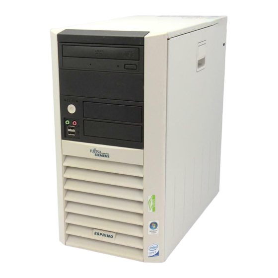
Summary of Contents for Fujitsu ESPRIMO P
- Page 1 ESPRIMO P Operating Manual...
- Page 2 ... any technical problems or other questions that you would like help with? Please contact: ● our Hotline/Help Desk (see the enclosed Help Desk List or look us up on the Internet: http://www.ts.fujitsu.com/support/helpdesk.html) ● your sales partner ● Your sales office Further information can be found in the "Safety"...
- Page 4 Published by Fujitsu Technology Solutions GmbH A26361-K1007-Z230-1-7619, Edition 1 2009/06 Produced by XEROX Global Services...
-
Page 5: Operating Manual
Introduction Important notes Preparing for use ESPRIMO P Operation Troubleshooting and tips Operating Manual System upgrades Technical data Index June 2009 edition... - Page 6 ESPRIMO is a registered trademark of Fujitsu Technology Solutions GmbH. Microsoft, MS, MS-DOS, Windows, Windows Vista and Windows NT are registered trademarks of the Microsoft Corporation. VESA and DPMS are trademarks of Video Electronics Standards Association. PS/2 is a registered trademark of International Business Machines, Inc.
-
Page 7: Table Of Contents
Contents Your ESPRIMO P ..........................1 Notational conventions ......................... 2 Important notes ..........................3 Safety notes............................3 Transporting the device ........................3 Cleaning the device ..........................3 Energy saving, disposal and recycling ....................4 CE marking............................4 FCC Class B Compliance Statement ....................5 Preparing for use.......................... - Page 8 Contents Tips 32 System upgrades ..........................33 Information about boards ........................33 Opening the casing ..........................34 Closing the casing..........................35 Installing the locking device with casing lock ..................36 Opening the drive cage ........................38 Closing the drive cage ........................38 Removing ventilation duct........................39 Ventilation duct: installing ........................40 Installing and removing a board ......................41 Installing a board.........................41 Removing boards........................43...
-
Page 9: Your Esprimo P
Your ESPRIMO P ..is available with various configuration levels with different hardware and software. You can incorporate operable drives (for example DVD drive) as well as other boards. This manual tells you how to put your device into operation and how to operate it in daily use. This manual applies for all configuration levels. -
Page 10: Notational Conventions
Your ESPRIMO P ... Notational conventions The meanings of the symbols and fonts used in this manual are as follows: This symbol indicates information which is important for your health or for preventing material damage. This symbol indicates important information which is required to use the system properly. -
Page 11: Important Notes
Important notes In this chapter you will find information regarding safety which it is essential to take note of when working with your device. Safety notes Pay attention to the information provided in the "Safety" manual and in the following safety notes. -
Page 12: Energy Saving, Disposal And Recycling
Important notes Energy saving, disposal and recycling Information on these topics can be found on the "Drivers & Utilities" CD/DVD or on our website http://ts.fujitsu.com. CE marking CE marking for devices shipped without wireless component up to 15.01./2007 The shipped version of this device complies with the requirements of the EEC directives 89/336/EEC "Electromagnetic compatibility"... -
Page 13: Fcc Class B Compliance Statement
● Consult the dealer or an experienced radio/TV technician for help. Fujitsu Technology Solutions GmbH is not responsible for any radio or television interference caused by unauthorized modifications of this equipment or the substitution or attachment of connecting cables and equipment other than those specified by Fujitsu Technology Solutions GmbH. The correction of interferences caused by such unauthorized modification, substitution or attachment will be the responsibility of the user. - Page 14 Important notes A26361-K1007-Z230-1-7619, edition 1...
-
Page 15: Preparing For Use
Preparing for use Please observe the safety information in the "Important notes" chapter. Unpacking and checking the delivery It is recommended not to throw away the original packaging material! It may be required for reshipment at some later date. ► Unpack all the individual parts. -
Page 16: Setting Up The Device
Preparing for use Setting up the device When installing your device, please read the recommendations and safety notes in the "Safety" manual. Set up the device only in its correct orientation (vertical position). We recommend that you place your device on a surface with good anti-slip qualities. In view of the multitude of different finishes and varnishes used on furniture, it is possible that the rubber feet will mark the surface they stand on. -
Page 17: Connecting The Monitor, Mouse And Keyboard
Preparing for use Connecting the monitor, mouse and keyboard The ports for the monitor, mouse, and keyboard are on the front and rear of the device. Keyboard port, purple USB port, black (optional) (USB mouse, USB keyboard) Monitor port, blue PS/2 mouse port, green (optional) Connecting the monitor... -
Page 18: Connecting The Mouse
Preparing for use Connecting the mouse Depending on the equipment level selected, your device will be supplied with a USB mouse or a PS/2 mouse. Connecting a USB mouse ► Connect the USB mouse to one of the USB ports on the device. -
Page 19: Connecting The Device To The Mains Voltage
Preparing for use Connecting the device to the mains voltage On devices without a voltage selector switch, the voltage supply is automatically adjusted to the mains voltage. On devices with a voltage selector switch (sliding switch, plug-in element) you will need to manually select the correct voltage rating. - Page 20 Preparing for use ► Connect the power cable to the device (1). ► Plug the power plug into a grounded mains outlet (2). A26361-K1007-Z230-1-7619, edition 1...
-
Page 21: Indicators Provided By The Device
Preparing for use Indicators provided by the device The indicators are on the front of the casing. Which indicators are available on your device depends on the configuration level you have selected. Drive indicator, e.g. DVD Hard disk indicator Floppy disk indicator Power-on indicator Hard disk indicator The indicator lights up when the hard disk drive of the device is accessed. -
Page 22: Switching On For The First Time: Installing The Software
Preparing for use Switching on for the first time: installing the software If the device is integrated into a network, the user and server details as well as the network protocol are required during the software installation. Contact your network administrator if you have any questions about these settings. -
Page 23: Switching On Monitor And Device
Preparing for use Switching on monitor and device ► Switch the monitor on (see the operating manual for the monitor). ► Switch the device on. To do this, follow the instructions below. Depending on the version, the device may be equipped with a main power switch on the back of the device in addition to the ON/OFF button on the front. -
Page 24: Installing The Software
Consult the operating system manual if anything is unclear about the input data requested by the system. You will find further information about the system, drivers, utilities, and updates on the "Drivers & Utilities" CD/DVD or on our website http://ts.fujitsu.com/support. A26361-K1007-Z230-1-7619, edition 1... -
Page 25: External Devices, Connecting
Preparing for use External devices, connecting Read the documentation on the external device before connecting it. With the exception of USB devices, always remove all power plugs before connecting external devices! Do not connect or disconnect cables during a thunderstorm. Always take hold of the actual plug. -
Page 26: Ports
Preparing for use Ports The connections are located on the front and back of the device. The ports available on your device depend on the configuration level you have selected. The standard ports are marked with the symbols shown below (or similar). Detailed information on the location of the connections is provided in the manual for the mainboard. -
Page 27: Connecting External Devices To The Parallel Or Serial Port
Preparing for use Connecting external devices to the parallel or serial port If your device has parallel and serial ports, you can connect external devices to these ports (such as a printer or modem). ► Connect the data cable to the external device. ►... - Page 28 Preparing for use A26361-K1007-Z230-1-7619, edition 1...
-
Page 29: Operation
Operation Switching the device on ► If necessary, switch the monitor on (see the operating manual for the monitor). ► Switch on the device with the main power switch located on the rear of the device (if present). ► Press the ON/OFF button on the front of the device. The power-on indicator lights green and the device is started. -
Page 30: Keyboard
Operation Keyboard Function keys Cursor keys Power button (optional) Numeric keypad (calculator keypad) Alphanumeric keypad The illustrated keyboard is an example and may differ from the model you use. Important keys and key combinations The description of the following keys and key combinations applies to Microsoft operating systems. Details of other keys and key combinations can be found in the documentation of the relevant application programme. - Page 31 Operation Start key calls up the Windows Start menu. (Windows XP) (Windows Vista) Menu key invokes the menu for the marked item (Windows). Shift key enables upper-case letters and the upper key symbols to be used. Alt Gr (e.g. German keyboard) Alt Gr produces a character shown on the right-hand side of a key (e.g.
-
Page 32: Settings In Bios Setup
Operation Settings in BIOS Setup In BIOS Setup you can set the system functions and the hardware configuration of the device. When the PC is delivered, the default entries are valid (see "BIOS Setup" manual or manual for the mainboard). You can customise these settings to your requirements in the BIOS Setup. Property and data protection Software functions and mechanical locking offer a broad range of functions for protecting your device and your personal data from unauthorised access. -
Page 33: Anti-Theft Protection And Lead-Sealing
Operation Anti-theft protection and lead-sealing Holes for padlock Device for "Kensington Lock" Anti-theft protection You can protect your device from theft. ● with the Kensington Lock device (2) and with a Kensington MicroSaver. Consult the manual for your Kensington Lock. ●... -
Page 34: Access Authorization Via Smartcard
Operation Access authorization via SmartCard In systems equipped with a SmartCard reader, access can be restricted to those users who have a corresponding SmartCard. Access protection with SystemLock With SystemLock you can protect your system from unauthorised booting. Then a system can only be booted when the user inserts a valid SmartCard in the SmartCard reader and enters his/her personal code number (PIN). -
Page 35: Troubleshooting And Tips
Troubleshooting and tips Refer to the safety notes in the "Safety" manual and in the "Preparing for use" chapter when connecting or disconnecting cables. If a fault occurs, try to correct it as described in the following places: ● in this chapter ●... -
Page 36: The Device Cannot Be Switched Off With The On/Off Switch
Troubleshooting and tips The device cannot be switched off with the ON/OFF switch. Cause Troubleshooting The device has not been switched on ► Press the ON/OFF switch again. with the ON/OFF switch. System crash ► Press the ON/OFF switch for at least 4 seconds, until the device switches off. - Page 37 Troubleshooting and tips Cause Troubleshooting Wrong monitor has been set under ► Restart the device. Windows 2000 ► If the message Starting Windows appears, press function key F8 The Windows 2000 Advanced Options Menu appears. ► Select Safe Mode or Safe Mode with Network. ►...
-
Page 38: No Mouse Pointer Displayed On The Screen
Troubleshooting and tips No mouse pointer displayed on the screen Cause Troubleshooting The mouse is not correctly ► Shut down the operating system properly. connected. ► Switch the device off. ► Check that the mouse cable is properly connected to the system unit. If you use an adapter or extension lead with the mouse cable, check the connections. -
Page 39: Time And/Or Date Is Not Correct
Troubleshooting and tips Time and/or date is not correct Cause Troubleshooting Time and date are incorrect. ► Set the correct time and date within the operating system you are using. ► Set the correct time and/or date in the BIOS Setup. The on-board backup battery in the ►... -
Page 40: Tips
Troubleshooting and tips Tips Topic Out of system resources If you have too many applications running at once, you may experience problems due to a lack of system resources. ► Close unnecessary applications. ► Run the applications in a different order. Other manuals Additional manuals are provided as PDF files on the "User Documentation"... -
Page 41: System Upgrades
System upgrades As the device has to be shut down in order to install/deinstall system hardware components, it is a good idea to print out the relevant sections of this chapter. It may be necessary to update the BIOS when carrying out a system expansion or hardware upgrade. -
Page 42: Opening The Casing
System upgrades Opening the casing ► Switch the device off. The device must not be in the energy-saving mode! Please observe the safety information in the "Important notes" chapter. Disconnect the mains plug from the mains outlet. Only insert the power plug after you have closed the casing. ►... -
Page 43: Closing The Casing
System upgrades Closing the casing ► Insert the side part in the guide rail on the lower part of the casing. ► Swivel the side part in the direction of the arrow (1) until it engages. ► On devices with a casing lock: Lock the casing. ►... -
Page 44: Installing The Locking Device With Casing Lock
System upgrades Installing the locking device with casing lock Removing the locking device ► Open the casing (see "Opening the casing"). ► Place the removed side part on a flat surface with the inside facing upwards. ► Press the catch in the direction of the arrow (1). ►... - Page 45 System upgrades Installing the locking device with casing lock ► Turn the removed side part over (so that the outside faces upwards). ► Guide the locking device with the casing lock in the direction of the arrow (1) into the side part. ►...
-
Page 46: Opening The Drive Cage
System upgrades Opening the drive cage ► Open the casing (see "Opening the casing"). ► Unscrew the knurled screw (1). ► Fold open the drive cage (2). Thanks to the integrated torque controller the drive cage will stop in any position. Closing the drive cage ►... -
Page 47: Removing Ventilation Duct
System upgrades Removing ventilation duct When removing the ventilation duct, be careful not to damage the processor cooler on the mainboard. ► Open the casing (see "Opening the casing"). ► Fold up the drive cage (see "Opening the drive cage"). ►... -
Page 48: Ventilation Duct: Installing
System upgrades Ventilation duct: installing When installing the ventilation duct, be careful not to damage the processor cooler on the mainboard. ► Insert the latches on the underside of the ventilation duct into the corresponding slots in the casing. ► Press the ventilation duct into the casing in the direction of the arrow (1) so that the locking hook is felt to engage. -
Page 49: Installing And Removing A Board
System upgrades Installing and removing a board Please take note of the section "Information about boards". When installing new boards, make sure that they do not interfere with existing boards. The number, position and arrangement of the board slots on the mainboard can be found in the manual for the mainboard. - Page 50 System upgrades ► Push the board into the slot (1). ► Press on the retaining clip until it noticeable engages (2). ► If necessary also secure the board with a screw. ► If necessary, connect the cables to the board. ►...
-
Page 51: Removing Boards
System upgrades Removing boards ► Open the casing (see "Opening the casing"). ► Fold up the drive cage (see "Opening the drive cage"). ► Disconnect the cables connected to the board. ► Press on the curved part of the retaining clip (1). ►... -
Page 52: Low-Profile Boards
System upgrades ► Close the casing (see "Closing the casing"). If you have installed or removed a PCI board, please check the relevant PCI slot settings in the BIOS Setup. If necessary, change the settings. Further information is provided in the PCI board documentation. -
Page 53: Installing And Removing Optional Ports
System upgrades Installing and removing optional ports An additional port (serial or parallel) can be installed in a rear slot cover plate like a board. For an exact description of how to connect external devices to ports, refer to the documentation for the external device. -
Page 54: Removing An Optional Port
System upgrades ► Push the port into the slot (1) as far as it will ► Press the port into the slot until you feel it engage. ► Press on the retaining clip until it you feel it engage (2). ►... -
Page 55: Installing And Removing Drives
System upgrades ► Push the rear slot cover plate into the slot (1). Ensure that the point of the cover engages on the outside of the casing. ► Press on the retaining clip until it you feel it engage (2). ►... - Page 56 System upgrades ► Press on the retaining clip (1) and, at the same time, slide it down slightly (2). ► Open the retaining clip. ► Slide the drive out of the bay in the direction of the arrow (3) from behind. The drive now protrudes slightly out of the casing.
-
Page 57: Installing An Accessible Drive
System upgrades Installing an accessible drive ► Open the casing (see "Opening the casing"). ► If a slide-in module is fitted, remove this first. To do this, proceed in the same way as when removing an accessible drive (see "Removing an accessible drive"). Do not dispose of the empty slide-in module. -
Page 58: Installing And Removing The Floppy Disk Drive
System upgrades Installing and removing the floppy disk drive ► Open the casing (see "Opening the casing"). ► Remove the data and power supply connectors from the floppy disk drive. ► Remove the screws (1) on the right side of the floppy disk drive. ►... -
Page 59: Installing And Removing The Hard Disk Drive
System upgrades Installing and removing the hard disk drive Removing a hard disk drive ► Open the casing (see "Opening the casing"). ► Fold up the drive cage (see "Opening the drive cage"). ► Slightly press together the EasyChange rails mounted on the hard disk (1) and pull the hard disk drive out of the drive cage in the direction of the arrow (2). -
Page 60: Installing A Hard Disk Drive
System upgrades ► Fold down the drive cage (see "Closing the drive cage"). ► Close the casing (see "Closing the casing"). Installing a hard disk drive ► Open the casing (see "Opening the casing"). ► Fold up the drive cage (see "Opening the drive cage"). EasyChange rails for a second hard disk drive are mounted on the drive cage. - Page 61 System upgrades ► Slide the hard disk drive with the EasyChange rails in the direction of the arrow (1) into the drive cage. Check that the component side of the hard disk drive faces inwards towards the casing. ► Fold down the drive cage (see "Closing the drive cage"). ►...
-
Page 62: Installing Usb Ports On The Rear Panel
System upgrades Installing USB ports on the rear panel A slot for USB ports is provided on the rear panel of the casing. As a result, no board slot is occupied when a second serial port is installed. ► Insert a screwdriver into the opening and break out the pre-stamped installation opening by moving it backwards and forwards. -
Page 63: Mainboard Expansions
System upgrades Mainboard expansions Details on how you can upgrade the main memory or the processor of your device are provided in the manual for the mainboard. Main memory, upgrading ► Open the casing (see "Opening the casing"). Fold up the drive cage (see "Opening the drive cage"). ►... -
Page 64: Replacing The Lithium Battery
System upgrades Replacing the lithium battery In order to permanently save the system information, a lithium battery is installed to provide the CMOS-memory with a current. A corresponding error message notifies the user when the charge is too low or the battery is empty. The lithium battery must then be replaced. Incorrect replacement of the lithium battery may lead to a risk of explosion! The lithium battery may be replaced only with an identical battery or with a type recommended by the manufacturer. -
Page 65: Technical Data
15 °C ..35 °C Transport (2K2) –25 °C ..60 °C Condensation must be avoided during operation. The data sheets of these devices contains further technical data. You will find the data sheets on the internet at http://ts.fujitsu.com. A26361-K1007-Z230-1-7619, edition 1... - Page 66 Technical data A26361-K1007-Z230-1-7619, edition 1...
-
Page 67: Index
Index Accessible drive Data protection 24 installing 55 Data, technical 65 removing 52 Date Alphanumeric keypad 22 not correct 34 Anti-theft protection 25 Device Audio input 18 Anti-theft protection 25 Audio output 18 cannot boot 30 checking rated voltage 11 cleaning 3 closing 38 Battery 63... - Page 68 Index Expansion 36 Alt Gr 23 Expansions Control 23 mainboard 62 Ctrl 23 External devices cursor keys 22 connecting 17, 19 Enter 22 ports 18 enter key 22 Num 23 ON/OFF switch 22 Return 22 Fault Shift 23 mouse 33 Key combination 22, 23 Fault Keyboard 22...
- Page 69 Index Monitor port 18 Mouse Safety notes 3 connecting 10 SCSI connection 18 fault 33 Security functions port 9 SmartCard 27 Mouse Cursor 33 Security functions Mouse port 18 BIOS setup 25 SmartCard 27 SmartLock 27 Security measures 24 New installation, software 34 Serial port 18, 19 Noise level 65 connecting devices 19...
- Page 70 Index Ventilation duct Warm boot 23 installing 44 Weight 65 removing 43 Video workstation 8 A26361-K1007-Z230-1-7619, edition 1...
Need help?
Do you have a question about the ESPRIMO P and is the answer not in the manual?
Questions and answers