Table of Contents
Advertisement
SERVICE MANUAL
Ver. 1.0
1998.07
MICROFILM
SPECIFICATIONS
Frequency range
FM : 65 – 108MHz
MW : 531 – 1,602kHz
LW : 153 – 279kHz
SW : 5.95 – 18MHz
IF
FM : 10.7MHz
MW/LW/SW : 455kHz
Aerials
FM/SW : Telescope
MW/LW : Built-in ferrite bar
Recording system
4-track, 2-channel stereo
Frequency response 70 – 13,000Hz
Speakers
Full range : 10cm (4 inches) dia., 6ohms,
cone type/Tweeter : 2cm (
Output
Headphones jack (stereo minijack), for
16 – 68 ohms impedance headphones
Maximum Power output
5W+5W
Battery life
FM Recording : Sony R20P : Approx. 10hours/
Sony LR20 alkaline : Approx. 20hours
Playback : Sony R20P : Approx. 3.5hours/
Sony LR20 alkaline : Approx. 8hours
Power requirements 230V AC, 50Hz
9V DC, six R20 (size D) batteries
Power consumption AC 18 W
Dimensions
Approx. 697 x 211 x 201.5 mm (w/h/d)
(27
1
/
x 8
3
/
2
8
controls, not incl. handle
Mass
Approx. 6.2 kg (13 lb 10 oz) incl. batteries
Supplied accessories
AC power cord (1)
Design and specifications are subject to change without notice.
CFS-515L
East European Model
Model Name Using Similar Mechanism
Tape Transport Mechanism Type
13
/
inches) dia.
16
x 8 inches) incl. projecting parts and
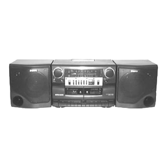
RADIO CASSETTE-CORDER
NEW
MF-W495-117
Advertisement
Table of Contents

Related Manuals for Sony SERVICE MANUAL


Summary of Contents for Sony SERVICE MANUAL
- Page 1 16 – 68 ohms impedance headphones Maximum Power output 5W+5W Battery life FM Recording : Sony R20P : Approx. 10hours/ Sony LR20 alkaline : Approx. 20hours Playback : Sony R20P : Approx. 3.5hours/ Sony LR20 alkaline : Approx. 8hours Power requirements 230V AC, 50Hz...
-
Page 2: Table Of Contents
WITH MARK ! ON THE SCHEMATIC DIAGRAMS AND IN THE order to meet same specifications. PARTS LIST ARE CRITICAL TO SAFE OPERATION. REPLACE THESE COMPONENTS WITH SONY PARTS WHOSE Therefore, the ceramic filter must changed two pieces together PART NUMBERS APPEAR AS SHOWN IN THIS MANUAL OR IN since it’s supply two pieces in one package as a spare parts. -
Page 3: General
SECTION 1 GENERAL LOOKING AT THE CONTROLS FRONT PANEL 5 6 7 9!º !¡ !™ !£ 1 Cassette compartments 9 PRESET MODE selector 2 MIC (microphone) !º BAND selector 3 PHONES (headphones) jack (stereo mini-jack) !¡ TUNING control 4 VOLUME control !™... -
Page 4: Disassembly
SECTION 2 DISASSEMBLY The equipment can be removed using the following procedure. BATT (–) board, BATT (+) board Power (AC) board, Power (DC) board Cabinet (Front) section Mechanism deck, REC SW board Chassis sub assy, Belt Cabinet (Rear) section VOL board, Main board ECM board Tuner board Note : Follow the disassembly procedure in the numerical order given. -
Page 5: Mechanism Deck, Rec Sw Board
2-4. MECHANISM DECK, REC SW BOARD 3 Screws (+BTP 3x10) 5 Screw (+PTT 2x6) Cabinet (Front) section REC SW board 3 Screws (+BTP 3x10) Mechanism deck section Cassette lid (L) Cassette lid (R) Button (ST/EJ) Button (ST/EJ) 2-5. CHASSIS SUB ASSY, BELT Deck A 2 Screw (+PTT 2x5) Deck B... -
Page 6: Vol Board, Main Board, Ecm Board
2-6. VOL BOARD, MAIN BOARD, ECM BOARD Knob (VOL) VOL board ECM board 2 Screw (+BTP 3x10) 5 Screw (+BTP 3x10) Main board 6 Screw (+BVTP 3x6) 2-7. TUNER BOARD 2 Knob (F/T) Chassis (Tune) Tuner board 1 Screw (+BTP 3x10) 1 Screw (+BTP 3x10) Claw Tuner board... -
Page 7: Dial Pointer Installation
SECTION 3 DIAL POINTER INSTALLATION Follow the installation procedure in the numerical order given. Note : Cabinet (Front) Pointer Marked line 2 – 2 Cabinet (Front) 2 – 1 1 Set the pointer into the grooves of the cabinet (Front) in the order of a, b and c. 2 Turn the knob (Tune) in the direction of the arrow, then set the pointer by aligning it with the marked line of the cabinet (Front). -
Page 8: Adjustments
IC201 TAPE SECTION 1. The adjustments should be performed in the order give in the service manual. (As a general rule, playbak circuit adjustment should be completed before performing recording circuit adjust- ment.) 2. The adjustments should be performed for both L-CH and R-CH unless otherwise indicated. - Page 9 TUNER SECTION 0dB = 1µV AM IF ADJUSTMENT Adjust for a maximum reading on level meter. • Switch location 455kHz FUNCTION switch RADIO • • • • • • • • • • • • • • • • • PRESET MODE MANUAL •...
- Page 10 FM VCO Adjustment Procedure : FM RF signal telescopic generator antenna terminal 0.01 µ F Carrier frequency : 90MHz Modulation : no modulation Output level : 65dB (1.8mV) 1. Connect the frequency counter to 4 and 7 pins of IC1 as shown the figure below.
-
Page 11: Diagrams
CFS-515L SECTION 5 DIAGRAMS 5-1. BLOCK DIAGRAM • Signal path. : FM : PB (L-CH) : PB (R-CH) : REC (L-CH) : REC (R-CH) – 11 – – 12 – – 13 –... - Page 12 CFS-515L Circuit Boards Location POWER (AC) board MAIN board VOL board BATT (+) board ECM board POWER (DC) board BATT (–) board TUNER board REC SW board Semiconductor Location Ref. No. Location Ref. No. Location D301 D417 H-10 D302 D418 H-10 D303 D419...
-
Page 13: Schematic Diagram - Main Section
CFS-515L 5-3. SCHEMATIC DIAGRAM – MAIN SECTION – Refer to page 14 for Note. Refer to page 23 for IC Block Diagrams. Waveforms 4.9Vp-p 45.5Vp-p 12.6 µ sec 12.6 µ sec T301 VOLT/DIV : 1 V AC T301 VOLT/DIV : 10 V AC TIME/DIV : 5 µsec TIME/DIV : 5 µsec –... -
Page 14: Printed Wiring Boards - Tuner Section
CFS-515L 5-4. PRINTED WIRING BOARDS – TUNER SECTION – 5-5. SCHEMATIC DIAGRAM – TUNER SECTION – Refer to page 24 for IC Block Diagram. Semiconductor Location Note: • X : parts extracted from the component side. Ref. No. Location • b : Pattern from the side which enables seeing. Note: •... - Page 15 IC Block Diagrams (Main Section) IC101, 201 BA5417 T. S. D ST. BY FILTER IC301 BA3426AS REC EQ REC EQ LOGIC – 23 –...
- Page 16 IC302 CXA1352AS 15dB 29dB VOLUME GRAPHIC EQUALIZER CONTROL BIAS GRAPHIC EQUALIZER 29dB VOLUME 15dB IC Block Diagram (T u ner Section) IC1 CXA1238S 26 25 24 23 22 21 FM FRONT-END AM FRONT-END FM IF / MPX REG. DISCRI PD 1 IF / DET COUNTER TUNING...
-
Page 17: Exploded Views
SECTION 6 EXPLODED VIEWS NOTE : • -XX, -X mean standardized parts, so they • The mechanical parts with no reference The components identified by mark ! may have some difference from the original number in the exploded views are not or dotted line with mark ! are critical one. -
Page 18: Cabinet (Front) Section
6-2. CABINET (FRONT) SECTION not supplied not supplied ECM301 supplied MF-W495-117 85 86 Ref. No. Part No. Description Remark Ref. No. Part No. Description Remark * 72 1-669-566-11 VOL BOARD 3-026-404-01 KNOB (F/T) 3-351-377-01 DAMPER 3-024-758-01 KNOB (TUNE) * 74 1-669-567-11 REC SW BOARD 3-024-741-11 LID (R), CASSETTE 3-024-766-01 SHAFT, MD... -
Page 19: Mechanism Deck Section-1
6-3. MECHANISM DECK SECTION-1 (MF-W495-117) HP901 (DECK A) HRP901 (DECK B) DECK B HE901 not supplied M301 DECK B Ref. No. Part No. Description Remark Ref. No. Part No. Description Remark 3-025-846-01 LEVER (REC) (DECK B) * 116 3-008-591-01 SLIDER (PAUSE) 3-933-025-01 SPRING (P), TORSION 3-933-004-01 CLAW, REEL 3-933-026-01 LEVER (P) -
Page 20: Mechanism Deck Section-2
6-4. MECHANISM DECK SECTION-2 (MF-W495-117) S503 (DECK B) S504 (DECK A) S501 (DECK B) S502 (DECK A) DECK B Ref. No. Part No. Description Remark Ref. No. Part No. Description Remark X-3373-572-1 REEL ASSY (N), T 3-933-029-01 LEVER, ERASING PREVENTION (DECK B) 3-939-383-02 SPRING, COMPRESSION 3-933-182-01 SPRING, CASSETTE 3-934-336-01 BEARING... -
Page 21: Speaker Section
6-5. SPEAKER SECTION SP101 (L-CH) SP201 (R-CH) SP102 (L-CH) SP202 (R-CH) supplied Ref. No. Part No. Description Remark Ref. No. Part No. Description Remark A-3320-364-A BOX (FRONT) SUB ASSY, SP (L-CH) * 204 1-670-292-11 RETAINER BOARD A-3320-367-A BOX (FRONT) SUB ASSY, SP (R-CH) SP101 1-505-965-11 SPEAKER (WOOFER) (L-CH) 1-690-969-11 CORD, SPEAKER CONNECTION... -
Page 22: Electrical Parts List
BATT (+) BATT (-) SECTION 7 ELECTRICAL PARTS LIST MAIN NOTE : • Due to standardization, replacements in the • SEMICONDUCTORS In each case, u : µ , for example : The components identified by mark ! parts list may be different from the parts uA.. - Page 23 MAIN Ref. No. Part No. Description Remark Ref. No. Part No. Description Remark C313 1-126-963-11 ELECT 4.7uF D416 8-719-991-33 DIODE 1SS133T-77 D417 8-719-991-33 DIODE 1SS133T-77 C314 1-126-961-11 ELECT 2.2uF D418 8-719-991-33 DIODE 1SS133T-77 C315 1-104-666-11 ELECT 220uF D419 8-719-991-33 DIODE 1SS133T-77 C316 1-124-443-00 ELECT 100uF...
- Page 24 MAIN POWER (AC) Ref. No. Part No. Description Remark Ref. No. Part No. Description Remark R204 1-249-417-11 CARBON 1/4W R205 1-249-428-11 CARBON 8.2K 1/4W R409 1-249-425-11 CARBON 4.7K 1/4W R410 1-249-429-11 CARBON 1/4W R206 1-247-807-31 CARBON 1/4W R411 1-247-843-11 CARBON 3.3K 1/4W R207...
- Page 25 POWER (DC) REC SW TUNER Ref. No. Part No. Description Remark Ref. No. Part No. Description Remark 1-669-565-11 POWER (DC) BOARD 1-102-959-00 CERAMIC 22PF 1-104-730-11 FILM 200PF 100V ***************** 1-136-287-11 FILM 0.0047uF 5% 100V 1-533-233-31 HOLDER, FUSE 1-107-734-11 FILM 360PF 100V 1-104-731-11 FILM 270PF...
- Page 26 1-223-761-11 RES, VAR, CARBON 50K (VOLUME) ************************************************************ MISCELLANEOUS ************** 1-533-233-31 HOLDER, FUSE 1-690-969-11 CORD, SPEAKER CONNECTION * 204 1-670-292-11 RETAINER BOARD Sony Corporation 98G0275075-1 Printed in Hungary © 1998.7 9-924-933-11 Personal A&V Products Company Published by Quality Engineering Dept. – 34 – (Shibaura)
Need help?
Do you have a question about the SERVICE MANUAL and is the answer not in the manual?
Questions and answers