Sony M-530V Service Manual
Microcassette-corder
Hide thumbs
Also See for M-530V:
- Operating instructions (2 pages) ,
- Operating instructions (2 pages) ,
- Operating instructions (2 pages)
Table of Contents
Advertisement
M-530V/535V/630V/635VK
SERVICE MANUAL
Ver 1.0 1999. 02
Tape
y (normal position type)
Recording system
2-track 1-channel monaural
Speaker
Approx. 3.6 cm (1
in.) dia.
7/16
Tape speed
2.4 cm/s (
ips), 1.2 cm/s (
15/16
15/32
Frequency range
250 - 4,000 Hz (with TAPE SPEED switch at 2.4 cm/s)
Input (M-635VK/630V only)
Microphone input jack (minijack/PLUG IN POWER)
sensitivity 0.24 mV for 3 kilohms or lower impedance microphone
Output
Earphone jack (minijack) for 8 - 300 ohms earphone
Power output (at 10% harmonic distortion)
250 mW
Power requirements
3 V DC batteries size AA (R6) × 2/External DC 3 V power sources
Dimensions (w/h/d)
Approx. 62.2 × 121.5 × 24.3 mm (2
parts and controls
Mass
Approx. 125 g (4.5
)
oz.
MICROFILM
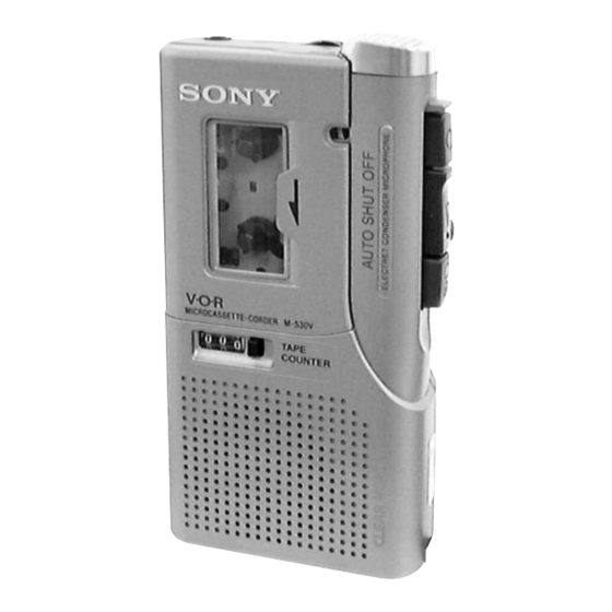
Photo : M-530V
SPECIFICATIONS
ips)
× 4
×
in.) incl. projecting
1/2
7/8
31/32
Model Name Using Similar Mechanism
Tape Transport Mechanism Type
Supplied accessories
AC power adaptor AC-E351 (1) (M-635VK only)
Battery charge adaptor BCA-35E (1) (M-635VK only)
Rechargeable batteries NC-AA, 1.2 V, 600 mAh, Ni-Cd (2) (M-635VK
only)
Microcassette tape MC-30 (1) (M-630V/535V/530V for Europe only)
Batteries R6P (SR) (2) (M-630V for Europe only)
Carrying case (1) (M-630V for Europe only)
Design and specifications are subject to change without notice.
MICROCASSETTE
– 1 –
US Model
Canadian Model
M-530V/535V/630V/635VK
AEP Model
E Model
M-530V/535V/630V
Chinese Model
M-630V
NEW
MZ-530V-99
TM
-CORDER
Advertisement
Chapters
Table of Contents

Related Manuals for Sony M-530V


Summary of Contents for Sony M-530V
- Page 1 Canadian Model Ver 1.0 1999. 02 M-530V/535V/630V/635VK AEP Model E Model M-530V/535V/630V Chinese Model M-630V Photo : M-530V Model Name Using Similar Mechanism Tape Transport Mechanism Type MZ-530V-99 SPECIFICATIONS Tape Supplied accessories y (normal position type) AC power adaptor AC-E351 (1) (M-635VK only)
-
Page 2: Table Of Contents
CRITIQUES POUR LA SÉCURITÉ DE FONCTIONNEMENT. NE circuit board (within 3 times). REMPLACER CES COMPOSANTS QUE PAR DES PIÈCES SONY • Be careful not to apply force on the conductor when soldering DONT LES NUMÉROS SONT DONNÉS DANS CE MANUEL OU or unsoldering. -
Page 3: General
SECTION 1 GENERAL This section is extracted from instruction manual. – 3 –... -
Page 4: Disassembly
SECTION 2 DISASSEMBLY • The equipment can be removed using the following procedure. Lid assy, Cabinet (rear) Main Mechanism Head, cassette assy board deck ceramic Lid, battery case unit Note : Follow the disassembly procedure in the numerical order given. 2-1. -
Page 5: Lid, Battery Case
2-2. LID, BATTERY CASE 3 claws 5 lid, battery case 2-3. CABINET (REAR) ASSY Note : When installing, fit the knobs and switches. 1 screw (1.7x16) 3 screw (B1.7x5), tapping 2 screw (1.7x16) 5 claw 6 cabinet (rear) assy knob switch 4 claws knob... -
Page 6: Main Board
2-4. MAIN BOARD 9 (M1.4x3.0), locking 1 Unsolder the 2 places. 2 Unsolder the 2 places. 0 (M1.4x3.0), locking 3 Unsolder the 4 places. 8 mic assy 4 Unsolder the 2 places. !¡ MAIN board 5 Unsolder the 2 places. 7 Unsolder. -
Page 7: Led Unit
2-6. LED UNIT 1 (1.7), tapping 2 bracket (LED) 3 LED unit 2-7. HEAD, CERAMIC 2 arm (pinch roller) assy 3 M1.4, special head 4 M1.4, special head 5 head, ceramic 1 claw – 7 –... -
Page 8: Mechanical Adjustments
SECTION 3 SECTION 4 MECHANICAL ADJUSTMENTS ELECTRICAL ADJUSTMENTS PRECAUTION Test Tape 1. Clean the following parts with a denatured-alcohol-moistened Tape Speed swab : Type Signal Used for (cm/s) record/playback/erase head pinch roller S-2-A030 3 kHz, – 20 dB Head Azimuth Adjustment rubber belts capstan 2. - Page 9 Tape Speed Adjustment Adjustment Location : First remove the plate, blind. Setting: VOL control : mechanical mid Remove the VOR switch : OFF plate, blind. Procedure: • Reform 2.4 cm/s speed adjustment before 1.2 cm/s speed adjustment mode : playback test tape digital frequency WS-24: tape speed 2.4cm/s...
-
Page 10: Diagrams
SECTION 5 DIAGRAMS • IC Block Diagrams IC101 LA4168ML PAUSE 2.2k Vref R, F SPEED POWER 300k IC501 MM1251BFBE (M-630V/635VK only) – VREF VOLTAGE UP – CIRCUIT – 10 –... -
Page 11: Block Diagram
M-530V/535V/630V/635VK 5-1. BLOCK DIAGRAM REC/PB AMP IC101 (1/2) 630V/635VK RV101 J102 MIC IN S101-4 PRE OUT POWER AMP – (REC/PB) (PLUG IN POWER) IC101 (2/2) ALC CONTROL PWR IN PWR OUT2 Q101 J101 MIC901 530V/535V S101-2 S103 (REC/PB) SP901 HRPE901... -
Page 12: Printed Wiring Board
M-530V/535V/630V/635VK 5-2. PRINTED WIRING BOARD HRPE901 REC/PB/ERASE HEAD (REC/PB) HD– (ERASE) HE– • Semiconductor Location Ref. No. Location Ref. No. Location D102 Q106 (D504) Q107 Q108 IC101 <Q109> (IC501) G-11 Q110 Q111 Q101 Q112 Note: Q102 Q113 • Y : parts extracted from the conductor side. -
Page 13: Schematic Diagram
M-530V/535V/630V/635VK 5-3. SCHEMATIC DIAGRAM • Refer to page 10 for IC Block Diagrams. Note: • All capacitors are in µF unless otherwise noted. pF: µµF • Voltage is dc with respect to ground under no-signal 50 WV or less are not indicated except for electrolytics condition. -
Page 14: Exploded Views
SECTION 6 EXPLODED VIEWS NOTE: Ref. No. Part No. Description Remark Ref. No. Part No. Description Remark • The mechanical parts with no reference • -XX and -X mean standardized parts, so • Accessories and packing materials are A-3021-217-A MAIN BOARD, COMPLETE (630V/635VK) 3-031-371-01 LID, BATTERY CASE (BLACK) (535V/630V:AEP) number in the exploded views are not supplied. -
Page 15: Mechanism Deck Section
6-2. MECHANISM DECK SECTION (MZ-530V-99) M901 HRPE901 Ref. No. Part No. Description Remark Ref. No. Part No. Description Remark 3-029-641-01 SPRING, TORSION 3-028-965-01 SPRING (PINCH ARM), TORSION 3-028-957-01 SPRING (CAM GEAR), TENSION 3-703-816-31 SCREW (M1.4), SPECIAL HEAD 3-028-966-01 GEAR (S-OFF-OW), CAM 3-703-816-73 SCREW (M1.4), SPECIAL HEAD X-3376-230-1 LIMITER ASSY 3-028-960-01 SPRING (AZIMUTH), COMPRESSION... -
Page 16: Electrical Parts List
SECTION 7 MAIN ELECTRICAL PARTS LIST NOTE: • Due to standardization, replacements in • SEMICONDUCTORS The components identified by the parts list may be different from the In each case, u : µ, for example: mark ! or dotted line with mark. parts specified in the diagrams or the uA.. - Page 17 MAIN Ref. No. Part No. Description Remark Ref. No. Part No. Description Remark < TRANSISTOR > R134 1-216-073-00 METAL CHIP 1/10W R135 1-216-025-00 RES,CHIP 1/10W Q101 8-729-800-37 TRANSISTOR 2SD1048-X7 R136 1-216-121-00 RES,CHIP 1/10W Q102 8-729-402-84 TRANSISTOR XN4601 R137 1-216-033-00 METAL CHIP 1/10W Q103 8-729-230-72 TRANSISTOR 2SA1362YG...
- Page 18 M-530V/535V/630V/635VK MAIN Ref. No. Part No. Description Remark Ref. No. Part No. Description Remark < VARIABLE RESISTOR > ACCESSORIES & PACKING MATERIALS ******************************** RV101 1-237-731-21 RES, VAR, CARBON 10K (VOL) RV601 1-223-584-11 RES, ADJ, CARBON 2.2K 1-528-405-31 ADAPTOR, BATTERY CHARGE (BCA-35E) (635VK) RV602 1-223-584-11 RES, ADJ, CARBON 2.2K...
- Page 19 Microcassette tape MC-30 (1) (M-630V/535V/530V for Europe only) 7/16 Tape speed Batteries R6P (SR) (2) (M-530V for Tourist and M-630V for Europe only) 2.4 cm/s ( ips), 1.2 cm/s ( ips) Carrying case (1) (M-530V for Tourist and M-630V for Europe only)
- Page 20 CRITIQUES POUR LA SÉCURITÉ DE FONCTIONNEMENT. NE circuit board (within 3 times). REMPLACER CES COMPOSANTS QUE PAR DES PIÈCES SONY • Be careful not to apply force on the conductor when soldering DONT LES NUMÉROS SONT DONNÉS DANS CE MANUEL OU or unsoldering.
-
Page 21: General
SECTION 1 GENERAL This section is extracted from instruction manual. – 3 –... -
Page 22: Disassembly
SECTION 2 DISASSEMBLY • The equipment can be removed using the following procedure. Lid assy, Cabinet (rear) Main Mechanism Head, cassette assy board deck ceramic (HRPE901) Lid, battery case unit Note : Follow the disassembly procedure in the numerical order given. 2-1. -
Page 23: Lid, Battery Case
2-2. LID, BATTERY CASE 3 claws 4 lid, battery case 2-3. CABINET (REAR) ASSY Note : When installing, fit the knobs and switches. 1 screw (1.7x16) 3 screw (B1.7x5), tapping 2 screw (1.7x16) 5 claw 6 cabinet (rear) assy knob switch 4 claws knob... -
Page 24: Main Board
2-4. MAIN BOARD 9 (M1.4x3.0), locking 1 Unsolder the 2 places. 2 Unsolder the 2 places. 0 (M1.4x3.0), locking 3 Unsolder the 4 places. 8 mic assy 4 Unsolder the 2 places. !¡ MAIN board 5 Unsolder the 2 places. 7 Unsolder. -
Page 25: Led Unit
2-6. LED UNIT 1 (1.7), tapping 2 bracket (LED) 3 LED unit 2-7. HEAD, CERAMIC (HRPE901) 2 arm (pinch roller) assy 3 M1.4, special head 4 M1.4, special head 5 head, ceramic 1 claw (HRPE901) – 7 –... -
Page 26: Mechanical Adjustments
SECTION 3 SECTION 4 MECHANICAL ADJUSTMENTS ELECTRICAL ADJUSTMENTS PRECAUTION Test Tape 1. Clean the following parts with a denatured-alcohol-moistened Tape Speed swab : Type Signal Used for (cm/s) record/playback/erase head pinch roller S-2-A030 3 kHz, – 20 dB Head Azimuth Adjustment rubber belts capstan 2. - Page 27 Tape Speed Adjustment Adjustment Location : First remove the plate, blind. Setting: VOL control : mechanical mid Remove the VOR switch : OFF plate, blind. Procedure: • Reform 1.2 cm/s speed adjustment before 2.4 cm/s speed adjustment mode : playback test tape digital frequency WS-24: tape speed 2.4cm/s...
-
Page 28: Diagrams
SECTION 5 DIAGRAMS • IC Block Diagrams IC101 LA4168ML PAUSE 2.2k Vref R, F SPEED POWER 300k IC501 MM1251BFBE (M-630V/635VK only) – VREF VOLTAGE UP – CIRCUIT – 10 –... -
Page 29: Block Diagram
M-530V/535V/630V/635VK 5-1. BLOCK DIAGRAM REC/PB AMP IC101 (1/2) 630V/635VK RV101 J102 MIC IN S101-4 PRE OUT POWER AMP – (REC/PB) (PLUG IN POWER) IC101 (2/2) ALC CONTROL PWR IN PWR OUT2 Q101 J101 MIC901 530V/535V S101-2 S103 (REC/PB) SP901 HRPE901... -
Page 30: Printed Wiring Board
M-530V/535V/630V/635VK 5-2. PRINTED WIRING BOARD HRPE901 REC/PB/ERASE HEAD (REC/PB) HD– (ERASE) HE– • Semiconductor Location Ref. No. Location Ref. No. Location D102 Q106 (D504) Q107 Q108 IC101 <Q109> (IC501) G-11 Q110 Q111 Q101 Q112 Note: Q102 Q113 • Y : parts extracted from the conductor side. -
Page 31: Schematic Diagram
M-530V/535V/630V/635VK 5-3. SCHEMATIC DIAGRAM • Refer to page 10 for IC Block Diagrams. Note: • All capacitors are in µF unless otherwise noted. pF: µµF • Voltage is dc with respect to ground under no-signal 50 WV or less are not indicated except for electrolytics condition. -
Page 32: Exploded Views
SECTION 6 EXPLODED VIEWS NOTE: Ref. No. Part No. Description Remark Ref. No. Part No. Description Remark • The mechanical parts with no reference • -XX and -X mean standardized parts, so • Accessories and packing materials are A-3021-217-A MAIN BOARD, COMPLETE (630V/635VK) 3-031-371-01 LID, BATTERY CASE (BLACK) (535V/630V:AEP) number in the exploded views are not supplied. -
Page 33: Mechanism Deck Section
6-2. MECHANISM DECK SECTION (MZ-530V-99) M901 HRPE901 Ref. No. Part No. Description Remark Ref. No. Part No. Description Remark 3-029-641-01 SPRING, TORSION 3-028-965-01 SPRING (PINCH ARM), TORSION 3-028-957-01 SPRING (CAM GEAR), TENSION 3-703-816-31 SCREW (M1.4), SPECIAL HEAD 3-028-966-01 GEAR (S-OFF-OW), CAM 3-703-816-73 SCREW (M1.4), SPECIAL HEAD X-3376-230-1 LIMITER ASSY 3-028-960-01 SPRING (AZIMUTH), COMPRESSION... -
Page 34: Electrical Parts List
SECTION 7 MAIN ELECTRICAL PARTS LIST NOTE: • Due to standardization, replacements in • SEMICONDUCTORS The components identified by the parts list may be different from the In each case, u : µ, for example: mark ! or dotted line with mark. parts specified in the diagrams or the uA.. - Page 35 MAIN Ref. No. Part No. Description Remark Ref. No. Part No. Description Remark < TRANSISTOR > R134 1-216-073-00 METAL CHIP 1/10W R135 1-216-025-00 RES,CHIP 1/10W Q101 8-729-800-37 TRANSISTOR 2SD1048-X7 R136 1-216-121-00 RES,CHIP 1/10W Q102 8-729-402-84 TRANSISTOR XN4601 R137 1-216-033-00 METAL CHIP 1/10W Q103 8-729-230-72 TRANSISTOR 2SA1362YG...
- Page 36 M-530V/535V/630V/635VK MAIN Ref. No. Part No. Description Remark Ref. No. Part No. Description Remark < VARIABLE RESISTOR > ACCESSORIES & PACKING MATERIALS ******************************** RV101 1-237-731-21 RES, VAR, CARBON 10K (VOL) RV601 1-223-584-11 RES, ADJ, CARBON 2.2K 1-528-405-31 ADAPTOR, BATTERY CHARGE (BCA-35E) (635VK) RV602 1-223-584-11 RES, ADJ, CARBON 2.2K...
- Page 37 M-530V/535V/630V/635VK US Model Canadian Model SERVICE MANUAL M-530V/535V/630V/635VK AEP Model E Model Ver 1.2 1999. 09 Chinese Model M-530V/535V/630V Tourist Model SUPPLEMENT-1 M-530V File this supplement with the service manual. Subject : • Change of Main Board • Corrections (ECN-MTA00149) Printed wiring board and schematic diagram of new type, and changed parts list are described in this Supplement-1.
- Page 38 M-530V/535V/630V/635VK 1. PRINTED WIRING BOARD TP19 TP13 TP33 TP18 TP32 TP30 TP20 TP14 TP28 TP29 TP39 TP27 TP23 TP26 TP40 TP21 TP36 TP34 TP22 HRPE901 TP35 REC/PB/ERASE HEAD (REC/PB) HD– TP17 TP12 TP15 TP25 (ERASE) HE– TP16 TP11 TP24 • Semiconductor Location Ref.
- Page 39 M-530V/535V/630V/635VK 2. SCHEMATIC DIAGRAM Note: • All capacitors are in µF unless otherwise noted. pF: µµF • Voltage is dc with respect to ground under no-signal 50 WV or less are not indicated except for electrolytics condition. and tantalums. no mark : PB •...
- Page 40 MAIN MAIN 3. ELECTRICAL PARTS LIST NOTE: Ref. No. Part No. Description Remark Ref. No. Part No. Description Remark • Due to standardization, replacements in • SEMICONDUCTORS When indicating parts by reference < COIL > R131 1-216-049-11 RES,CHIP 1/10W the parts list may be different from the In each case, u : µ, for example: number, please include the board.
- Page 41 MAIN Ref. No. Part No. Description Remark R608 1-216-065-11 RES,CHIP 4.7K 1/10W < VARIABLE RESISTOR > RV101 1-237-731-21 RES, VAR, CARBON 10K (VOL) RV601 1-223-584-11 RES, ADJ, CARBON 2.2K RV602 1-223-584-11 RES, ADJ, CARBON 2.2K < SWITCH > S101 1-572-964-11 SWITCH, SLIDE (REC/PB) S102 1-572-688-11 SWITCH, PUSH (1 KEY) (POWER) S103...
- Page 42 • Correction of Exploded View Page 17, 18 NOTE: • Items marked “*” are not stocked since • Color Indication of Appearance Parts • Accessories and packing materials are they are seldom required for routine service. Example : given in the last of this parts list. Some delay should be anticipated KNOB, BALANCE (WHITE) ...
- Page 43 Ref. No. Part No. Description Remark Ref. No. Part No. Description Remark A-3021-217-A MAIN BOARD, COMPLETE (630V/635VK) 3-037-004-01 PLATE, SHIELD A-3021-219-A MAIN BOARD, COMPLETE (530V/535V) 3-031-371-01 LID, BATTERY CASE (BLACK) (535V/630V:AEP) 3-704-197-31 SCREW (M1.4X3.0), LOCKING 3-031-371-11 LID, BATTERY CASE (SILVER) 3-831-441-99 SPACER, KNOB (530V/630V/635VK) 3-034-687-01 TERMINAL (-), BATTERY...
- Page 44 M-530V/535V/630V/635VK • Correction of Electrical Adjustment Page 9 : indicates corrected portion. Note : Following corrections ( ) have been already corrected in the service manual (Part No. 9-926-961-12) and they are only for the service manual (Part No. 9-926-961-11).
Need help?
Do you have a question about the M-530V and is the answer not in the manual?
Questions and answers