Table of Contents
Advertisement
Quick Links
SERVICE MANUAL
S MECHANISM
• Refer to the SERVICE MANUAL of VHS MECHANICAL
ADJUSTMENTS VI for MECHANICAL ADJUSTMENTS.
(9-921-647-11)
System
Format
Video recording system
Video heads
Video signal
General
Power requirements
Power consumption
Operating temperature
SPECIFICATIONS
VHS NTSC standard
Rotary head helical scanning
FM system
Double azimuth four heads
NTSC color, EIA standards
120 V AC, 60 Hz
24 W (US, Canadian)
18 W (Mexican)
5˚C to 40˚C (41˚F to 104˚F)
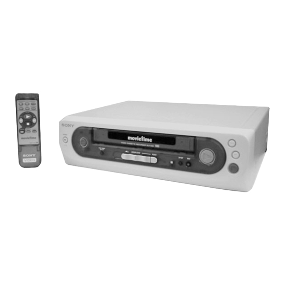
SLV-KS1
Approx. 355 × 96 × 285.5 mm
Dimensions
(w/h/d)
(Approx. 14 × 3
inches) including projecting
parts and controls
Mass
Approx. 3.6 kg (7lb 15oz)
Supplied accessories
Remote control (1)
Size AA (R6) batteries (2)
Audio/video cable (3-phono to 3-phono) (1)
Design and specifications are subject to change without
notice.
VIDEO CASSETTE RECORDER
RMT-V301
US Model
Canadian Model
Mexican Model
× 11
7
1
/
/
8
4
Advertisement
Table of Contents

Related Manuals for Sony SLV-KS1


Summary of Contents for Sony SLV-KS1
- Page 1 SLV-KS1 RMT-V301 SERVICE MANUAL US Model Canadian Model Mexican Model S MECHANISM • Refer to the SERVICE MANUAL of VHS MECHANICAL ADJUSTMENTS VI for MECHANICAL ADJUSTMENTS. (9-921-647-11) SPECIFICATIONS Approx. 355 × 96 × 285.5 mm System Dimensions (w/h/d) Format VHS NTSC standard (Approx.
- Page 2 SONY PARTS WHOSE PART NUMBERS APPEAR AS DE FONCTIONNEMENT. NE REMPLACER CES COM- SHOWN IN THIS MANUAL OR IN SUPPLEMENTS PUB- POSANTS QUE PAR DES PIÈCES SONY DONT LES LISHED BY SONY. NUMÉROS SONT DONNÉS DANS CE MANUEL OU DANS LES SUPPLÉMENTS PUBLIÉS PAR SONY.
-
Page 3: Table Of Contents
TABLE OF CONTENTS Section Title Page Section Title Page SERVICE NOTE ..............4 ADJUSTMENTS 6-1. Mechanical Adjustments ..........6-1 GENERAL 6-2. Electrical Adjustments ........... 6-1 2-1. Pre-Adjustment Preparations ........6-1 Play Timer ..............1-1 2-1-1. Instruments to be Used ..........6-1 Cassette Door Lock (Safety Lock) ........ -
Page 4: Service Note
SERVICE NOTE 1. DISASSEMBLY • This set can be disassembled in the order shown below. Note: Pages in indicated pages in the SERVICE MANUAL. Pages in indicated pages in the VHS MECHANICAL ADJUSTMENT MANUAL VI. Upper Case (Page 2-1) Front Panel Pinch Press Ground Shaft Rear Panel... -
Page 5: General
SLV-KS1 SECTION 1 This section is extracted from instruc- GENERAL tion manual. (3-062-072-11) Step Step Step Turn on your TV Insert your Press to and press your TV’s tape here play! TV/VIDEO* button Press to * The name of this button may be different on your TV. -
Page 6: Connections
Connections Follow the steps below to connect your TV to the VCR. Your TV AUDI O (MONO ) VIDEO LINE IN LINE OUT AUDI O VIDEO AUDIO VIDEO OUT AUDIO IN R VIDEO IN to an AC outlet AUDIO IN L Step Using the supplied audio/video cable, connect one of the yellow plugs to VIDEO of LINE OUT on this VCR, and the other yellow plug to VIDEO of LINE IN on your TV. -
Page 7: Disassembly
SLV-KS1 SECTION 2 DISASSEMBLY Note: Follow the disassembly procedure in the numerical order given. 2-1. UPPER CASE REMOVAL 2-3. REAR PANEL (M) REMOVAL 1 Power cord 7 Rear panel (M) (CN600) 1 Two tapping screws 4 Claw 3 Upper case... -
Page 8: Ma-370 Board Removal
2-5. MA-370 BOARD REMOVAL 1 Five screws (B3) 2 MA-370 board... -
Page 9: Internal Views
2-6. INTERNAL VIEWS Drum assembly (M901) (DZH-0A2A/Z-RP) ACE head block assembly 8-839-049-53 A-6759-620-A FE head 1-500-144-11 Q001 Tape end sensor 8-729-043-84 Q002 Tape top sensor 8-729-043-84 D001 Tape top/end LED 8-719-048-26 Drum assembly (M901) (DZH-0A2A/Z-RP) 8-839-049-53 M902 Capstan motor 1-698-971-11 M903 Cam motor assembly X-3947-577-1... -
Page 10: Circuit Boards Location
2-7. CIRCUIT BOARDS LOCATION QP-1 (KIDS SOUND) MA-370 HEAD AMP, VIDEO, AUDIO, I/O, SERVO/SYSTEM CONTROL, POWER SUPPLY, MODE CONTROL 2-4 E... -
Page 16: Frame Schematic Diagram
SLV-KS1 SECTION 4 PRINTED WIRING BOARDS AND SCHEMATIC DIAGRAMS THIS NOTE IS COMMON FOR PRINTED WIRING For schematic Diagram: • Caution when replacing chip parts. BOARDS AND SCHEMATIC DIAGRAMS. New parts must be attached after removal of chip. (In addition to this, the necessary note is printed Be careful not to heat the minus side of tantalum capacitor, in each block.) - Page 27 SLV-KS1 SECTION 5 INTERFACE, IC PIN FUNCTION DESCRIPTION...
- Page 30 5-4 E...
-
Page 31: Adjustments
SLV-KS1 SECTION 6 ADJUSTMENTS 2-1-3. Set-up of Adjustment During the adjustment, see the Parts Arrangement In this adjustment, NTSC pattern generator is connected with LINE Diagram for Adjustments on Page 6-4. input signal terminal. When check to tuner, connected AERIAL terminal. -
Page 32: Adjusting Sequence
2-1-6. Adjusting Sequence 2-3. SERVO SYSTEM ADJUSTMENT Make the electrical adjustment in the following sequence. 2-3-1. RF Switching Position Adjustment Checking power supply (MA-370 Board) Purpose: Adjust the interval between A ch and B ch of tape playback out- put. Servo system adjustment Improve the interchangeability with other tapes and sets. -
Page 34: Repair Parts List
SLV-KS1 SECTION 7 REPAIR PARTS LIST 7-1. EXPLODED VIEWS The components identified by mark 0 or dotted line with mark 0 are critical for safety. NOTE: Replace only with part number speci- • The mechanical parts with no reference number in •... -
Page 35: Mechanism Chassis Assembly (1)
7-1-2. MECHANISM CHASSIS ASSEMBLY (1) Ref. No. Part No. Description Remark Ref. No. Part No. Description Remark 3-977-509-01 WASHER, THRUST 3-977-514-01 OPENER, LID 3-977-507-01 TABLE, REEL (S) (GRAY) 3-977-441-03 GEAR, PINCH PRESSING 3-977-508-01 TABLE, REEL (T) (BLACK) 3-977-445-02 GEAR, TG8 ARM DRIVING 1-500-144-11 HEAD, FE 3-977-465-01 SPRING, EXTENSION (RVS BRAKE) 3-977-495-01 SHAFT TG2... -
Page 36: Mechanism Chassis Assembly (2)
7-1-3. MECHANISM CHASSIS ASSEMBLY (2) Ref. No. Part No. Description Remark Ref. No. Part No. Description Remark X-3947-581-4 BRAKE ASSY, MAIN (T) A-6750-324-A SHUTTLE (S) BLOCK ASSY 3-977-462-01 SPRING, EXTENTION. (MAIN BRAKE) X-3944-378-1 ROLLER ASSY, GUIDE X-3947-573-1 ARM ASSY, PENDULUM 3-965-178-01 SPRING X-3947-580-5 BRAKE ASSY, MAIN (S) 3-969-632-04 BASE, DRUM... -
Page 37: Mechanism Chassis Assembly (3)
7-1-4. MECHANISM CHASSIS ASSEMBLY (3) M902 M903 Ref. No. Part No. Description Remark Ref. No. Part No. Description Remark 3-977-437-01 RETAINER, CAM MOTOR 3-977-442-03 SLIDER X-3947-584-1 ASSY, REEL DIRECT 3-977-455-01 GEAR, LOADING (T) 3-977-443-01 WASHER, STOPPER 3-977-456-03 SPRING, TORSION (LOAD T) 3-977-438-01 WORM - WHEEL X-3947-579-1 LEVER ASSY, LOADING (T) 3-977-506-01 ARM, LIMITTER SELECTION... -
Page 38: Electrical Parts List
MA-370 7-2. ELECTRICAL PARTS LIST NOTE: The components identified by • Due to standardization, replacements in the • Items marked “*” are not stocked since they mark 0 or dotted line with mark parts list may be different from the parts speci- are seldom required for routine service. - Page 39 MA-370 Ref. No. Part No. Description Remark Ref. No. Part No. Description Remark C247 1-163-037-11 CERAMIC CHIP 0.022uF C514 1-163-009-11 CERAMIC CHIP 0.001uF C248 1-163-809-11 CERAMIC CHIP 0.047uF C249 1-109-982-11 CERAMIC CHIP C561 1-164-232-11 CERAMIC CHIP 0.01uF C250 1-163-809-11 CERAMIC CHIP 0.047uF C562 1-104-664-11 ELECT...
- Page 40 MA-370 Ref. No. Part No. Description Remark Ref. No. Part No. Description Remark D605 8-719-911-19 DIODE 1SS119-25TD JR020 1-216-295-00 METAL CHIP 1/10W D607 8-719-022-97 DIODE D2S4MF JR021 1-216-295-00 METAL CHIP 1/10W JR022 1-216-295-00 METAL CHIP 1/10W D608 8-719-073-18 DIODE S3L20UF34 JR023 1-216-295-00 METAL CHIP 1/10W...
- Page 41 MA-370 Ref. No. Part No. Description Remark Ref. No. Part No. Description Remark JR099 1-216-295-00 METAL CHIP 1/10W < TRANSISTOR > JS303 1-216-295-00 METAL CHIP 1/10W Q101 8-729-043-84 TRANSISTOR PT380F3 (T.SENS) JS363 1-216-296-00 METAL CHIP 1/8W Q102 8-729-043-84 TRANSISTOR PT380F3 (S.SENS) JS364 1-216-296-00 METAL CHIP 1/8W...
- Page 42 MA-370 Ref. No. Part No. Description Remark Ref. No. Part No. Description Remark R188 1-216-069-00 METAL CHIP 6.8K 1/10W R383 1-216-031-00 METAL CHIP 1/10W R189 1-216-061-00 METAL CHIP 3.3K 1/10W R401 1-216-025-91 RES-CHIP 1/10W R190 1-249-417-11 CARBON 1/4W R402 1-249-437-11 CARBON 1/4W R191 1-249-417-11 CARBON...
- Page 43 MA-370 QP-1 Ref. No. Part No. Description Remark Ref. No. Part No. Description Remark 0 R641 1-219-123-11 FUSIBLE 0.47 1/4W < RESISTOR > R642 1-243-858-41 METAL OXIDE R643 1-216-061-00 METAL CHIP 3.3K 1/10W R998 1-216-121-91 RES-CHIP 1/10W R645 1-260-066-91 CARBON 1/2W R999 1-216-049-00 METAL CHIP...
- Page 44 SLV-KS1 Sony Corporation 2000E053022-1F 9-921-761-11 Network Entertainment Group Printed in Japan C 2000. 5 – 66 – Published by Quality Assurance Dept.
Need help?
Do you have a question about the SLV-KS1 and is the answer not in the manual?
Questions and answers