
Related Manuals for IKUSI ONE SAT 118


Summary of Contents for IKUSI ONE SAT 118
- Page 1 Manual de usuario User manual Notice d’utilisation SAT / 118 / 123 REF. 2844 / 2845 / 2846 Amplifi cador con fi ltros programables Programmable multichannel amplifi er Centrale d’amplifi cation Programmable...
-
Page 5: Table Of Contents
Contents General safety instructions Types of notices Basic safety instructions Introduction General description Main features General equipment use Equipment installation and confi guration Installation Power connection Quick menu guide Language selection Manual setting Advanced settings Self-installation Maintenance Equipment care Troubleshooting Technical specifi... -
Page 6: General Safety Instructions
General safety instructions Read all of this user manual carefully before plugging in the equipment. Always have these instructions to hand during installation. Follow all of the instructions and safety notices regarding equipment handling. Types of notices The meaning of the safety notices used in this manual are described below. -
Page 7: Basic Safety Instructions
General safety instructions / Basic safety instructions Basic safety instructions DANGER OF DEATH OR INJURY Do not install the equipment during an electrical storm. This could lead to electrostatic discharge from lightning. DANGER Do not open the equipment. This could lead to electric discharge. ... -
Page 8: Introduction
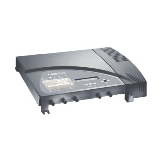
Introduction General description BI-FM input BIII-DAB input VHF-UHF/EXT input ** UHF3 input UHF2 input UHF1 input SAT-IF1 input * Mains connector Control button 10 Screen (LCD) 11 Front panel with cluster map 12 SAT-IF2 input with no amplifi cation * 13 Output 2;... - Page 9 Introduction / Main features Reprogrammable as many times as required. 10 tuneable UHF fi lters with the capacity to process 1 to 5 channels each. Signal processing: Terrestrial inputs with low noise fi gure (< 6 dB). ...
-
Page 10: General Equipment Use
Introduction / General equipment use 1 Test output. VHF output level = 118 dBμV. UHF output level = 123 dBμV. IMD3-60 dB, DIN 45004B (see channel reduction table in Technical Annex) ONE SAT Model Recommended for small and medium-sized installations, comprising 10 UHF fi lters it in- cludes one satellite input and two mixed television-satellite outputs. - Page 11 Introduction / General equipment use This acronym is displayed in the main menu. Select it to go back to the language selection menu. ▲ This symbol is displayed in manual settings and advanced settings and ▼ visually indicates the possibility of moving vertically. This symbol is displayed in manual and advanced settings and always includes a numeric value and visually indicates the gain level.
-
Page 12: Equipment Installation And Confi Guration
Equipment installation and confi guration / Installation Equipment installation and confi guration Only the LCD screen and the button are required to confi gure the equipment. Follow the steps below to install the equipment and confi gure the different parameters. Installation RISK OF EQUIPMENT DAMAGE BI-FM... - Page 13 Equipment installation and confi guration / Power connection Language selection Manual setting Advanced settings Self-installation Filter allocation to aerials (7-0-3) (9-0-1) (10-0-0) (2-5-3) (2-7-1) Mast-head amplifi er power Mast-head amplifi er power General gain BI - BII input BIII-DAB input VHF-UHF/EXT UHF output input...
-
Page 14: Quick Menu Guide
Equipment installation and confi guration / Quick menu guide Quick menu guide Language selection NOTE Over the following pages, the fi eld locating and selection method is primarily indicated by the “vertical button movement” and “press button” icons. However, horizontal button movement can be used to locate and select fi elds, as indicated in the General equipment use section on Page 8. - Page 15 Equipment installation and confi guration / Manual setting For two aerials: Confi guration (9 – 0 – 1) Confi guration (7 – 0 – 3) For three aerials: Confi guration (2 – 5 – 3) Confi guration (2 – 7 – 1) Mast-head amplifi...
- Page 16 Equipment installation and confi guration / Manual setting Gain confi guration: NOTE If AUT is selected, the equipment adjusts the gain automatically and completes gain confi guration for the fi lter selected. If M is selected, you adjust the gain manually. Locate and select the gain confi guration mode AUT / M.
-
Page 17: Advanced Settings
Equipment installation and confi guration / Advanced settings SAT-IF output adjustment LNB power confi guration NOTE There are 5 different confi gurations to select polarisation. Locate and select polarisation: No polarisation: LNB, OFF. 18 V with tones: LNB, 18 V. 18 V without tones: LNB, 18 V. - Page 18 Equipment installation and confi guration / Advanced settings Equipment confi guration cloning NOTE Cloning begins automatically after the following steps. Connect two equipments using a coaxial cable in the Test 1 output of each equipment (see position (15) in the illustration in the General Description section on page 6).
-
Page 19: Self-Installation
Equipment installation and confi guration / Self-installation Specifi c equipment information NOTE Information on the equipment, the pro- gramme version, the manufacturing date, the number of hours operating, the tem- perature and the equipment serial number are displayed on the screen. Restore factory values CAUTION This function will mean that all previous... - Page 20 Equipment installation and confi guration / Self-installation NOTE The equipment displays information on the status of self-installation. Please wait a few seconds until it is completed and AUTOINSTALL COMPLETED is displayed. Select OK to complete self-installation. To manually confi gure the output level of gene- ral gains, see: Adjusting general gains section on Page 14.
-
Page 21: Maintenance
Maintenance Equipment care HANDLING THE INSIDE OF THE EQUIPMENT IS FORBIDDEN Do not dismantle or try to repair the equipment, its accessories or its compo- nents. This will render the warranty null and void. Do not use the power cable if it is damaged. ... -
Page 22: Technical Specifi Cations
Technical specifi cations ONE 118 Model (AFP-201) BI-FM BIII-DAB UHF1 UHF2 UHF3 Inputs Band width 47-108 174-240 470-862 Input confi guration Number of programmable UHF fi lters per input 35 / 55 Gain (switchable) Gain adjustment Noise fi gure <6 <6 <6 50-80... -
Page 23: One 123 Model (Afp-211)
Technical specifi cations / ONE 123 Model (AFP-211) ONE 123 Model (AFP-211) (VHF/ BI-FM BIII-DAB UHF1 UHF2 UHF3 UHF) Inputs 47-240 / Band width 47-108 174-240 470-862 470-862 Input confi guration Number of programmable UHF fi lters per input 40 / 60 Gain (switchable) Gain adjustment... -
Page 24: One Sat Model (Afp-292)
Technical specifi cations / ONE SAT Model (AFP-292) ONE SAT Model (AFP-292) (VHF/ FI-SAT BI-FM BIII-DAB UHF1 UHF2 UHF3 SAT-IF (passive) UHF) Inputs 47-240 / 950- 950- Band width 47-108 174-240 470-862 470-862 2150 2150 Input confi guration Number of programma- ble UHF fi lters per input 35 / 55 Gain... - Page 25 Technical specifi cations / ONE SAT Model (AFP-292) Outputs (2) TV+IF Output level* dBμV 113 / 118 Output level adjustment Return losses >10 Test outputs (2) Operations Mains voltage 230 - 240 V~ Consumption 0.25 A / 25 W Operating temperature -5 to 50 ºC Mains connector IEC C8...
-
Page 26: Technical Annex
Technical annex Output level reduction in broadband amplifi ers BROADBAND TERRESTRIAL TV AMPLIFIERS : The RF output levels specifi ed in this catalogue for IMD3=-60 dB (DIN 45004 B) are applicable when 2 analog TV channels are amplifi ed. If, as is usual, more than 2 TV channels are amplifi ed, such levels have to be reduced according to the following table: Number of Channels (n) -
Page 27: Warranty
During the warranty period, IKUSI is responsible for any faults arising due to material or manufacturing defects and shall repair the receiver or replace it for another corresponding to the state of technology at that time. -
Page 28: Ce Certifi Cate
CE Certifi cate By reproducing the CE marking, IKUSI guarantees equipment compliance with the corresponding harmonised standards. EC-Declaration of Conformity marking We, Manufacturer IKUSI, Angel Iglesias, S.A. Paseo Miramón, 170 E-20009 San Sebastián, Spain declare that the products Programmable Terrestrial&Satellite Multiband Amplifiers... - Page 32 Ángel Iglesias, S.A. Paseo Miramón, 170 20009 San Sebastián, Spain Tel. +34 943 44 88 00 Fax +34 943 44 88 20 ikusi@ikusi.com www.ikusi.com 120108A...
Need help?
Do you have a question about the ONE SAT 118 and is the answer not in the manual?
Questions and answers