
Subscribe to Our Youtube Channel
Related Manuals for elero VarioTec


Summary of Contents for elero VarioTec
- Page 1 VarioTec Operating instructions Please keep these instructions in a safe place! elero GmbH Antriebstechnik Linsenhofer Str. 59–63 D-72660 Beuren info@elero.de www.elero.com 309023 Nr. 18 100.3401/0204...
-
Page 2: Table Of Contents
Risk of injury by electric shock. Warning! Installation/Connection VarioTec ......GB- 5 • All terminal connections to a 230 V network Connection as a drive controller . -
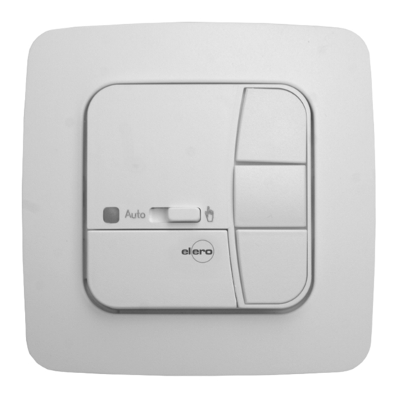
Page 3: Explanation Of Displays And Buttons
UP button sliding switch commands. STOP button Alarm signal The VarioTec device can be operated manually at all times. Auto control light The VarioTec is characterised by its user-friendly operation. DOWN button Cover... -
Page 4: Installation/Connection Variotec
5. Insert the operating device into the frame and plug it into the power supply unit. Note: The encoding switch located on the back of the VarioTec Connection as a group controller device can be used to select group or drive control. -
Page 5: Factory Settings
Explanation of functions Explanation of functions Factory settings Reset button: Press the Reset button (with a ballpoint pen or similar object) to Encoding switch factory setting delete the intermediate position and the ventilation/reverse position. 1. Lower position Alarm signal function ON. POS B: 2. -
Page 6: Selecting Roller Shutter/Awning Or Venetian Blind
Programming menu Drive controller: Programming If the VarioTec device is being used as a drive controller, the drive is directly connected to the VarioTec device, in which case external Programming the intermediate position signals are converted into control commands. Encoding switch 2 must be set to the lower position. -
Page 7: Adjustment To Intermediate Position
General declaration of conformity: Press and hold the Pos V programming button for more than The company elero GmbH hereby declares that the VarioTec device 5 seconds. The ventilation/reverse position is now deleted. complies with the basic requirements and other relevant regulations The control light will flash 3 times briefly. - Page 8 Warnhinweise GB-13 GB-14...
Need help?
Do you have a question about the VarioTec and is the answer not in the manual?
Questions and answers