Table of Contents
Advertisement
Quick Links
Advertisement
Table of Contents

Related Manuals for Varytec FLATBEAM DUO 48x8W RGBW


Summary of Contents for Varytec FLATBEAM DUO 48x8W RGBW
- Page 1 User manual FLATBEAM DUO 48x8W RGBW...
-
Page 2: Table Of Contents
Table of contents Safety instructions ..........................4 1.1. FOR SAFE AND EFFICIENT OPERATION ................4 Before usage ............................ 5 2.1. Carton ............................5 2.2. Unpacking ..........................5 2.3. AC Power ..........................5 Introduction ............................5 3.1. Features ........................... 5 3.2. DMX Channel summery ...................... - Page 3 5.6.8. Setting ..........................15 5.6.9. RGbW White adjust ....................... 16 5.6.10. CAL1 ..........................16 5.6.11. CAL2 ..........................16 5.6.12. Key Lock ........................16 5.7. DMX 512 channel values ....................... 17 DMX Primer ............................ 20 3 / 21...
-
Page 4: Safety Instructions
1. Safety instructions • This device is suitable for indoor use only. • All modifications to the device will void the warranty. • Repairs are to carry out by skilled personnel only. • Use only fuses of the same type and original parts as spare parts. •... -
Page 5: Before Usage
Important: Damages caused by the disregard of this user manual are not subject to warranty. The dealer will not accept liability for any resulting defects or problems. Make sure the electrical connection is carried out by qualified personnel. All electrical and mechanical connections have to be carried out according to the European safety standards. -
Page 6: Dmx Channel Summery
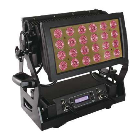
Voltage: 100V – 240V 50Hz~60Hz Power supply: built in and auto switching Size: 508 x 196 x 533mm Net weight: 23kg 3.2. DMX Channel summery The Flatbeam has a total of 7 DMX channel configurations, referred to as “personalities” in this manual and in the fixture onboard control board. -
Page 7: Product Overview
Ar.2d Channel Description Dimmer Green Blue White Ar.2s Channel Description Dimmer Green Blue White Strobe Channel Description Saturation Value (Brightness) 3.3. Product Overview 7 / 21... -
Page 8: Setup
4. Setup 4.1. Power Supply Before plugging in your unit, make sure that the voltage in your area is matching the required voltage of your Flatbeam. This unit has an auto switching PSU which offers a wide range of input voltages. The only thing you have to do before powering up, is to check if the line voltage you are connected to is matching the range of accepted voltages. -
Page 9: Fixture Linking
4.3. Fixture linking You will need a serial data link to run light shows of one or more fixtures using a DMX 512 controller or to run synchronized shows on two or more fixtures set to a master/slave operating mode. The combined number of channels required by all fixtures on a serial data link determines the number of fixtures the data link can support. -
Page 10: Cable Connectors
4.3.3. Cable Connectors Cabling must have a male XLR connector onone end and a female XLR connector on the other end Caution! Do not allow contact between the common and the fixtures chassis ground. Grounding the common can cause a ground loop, and your fixture may perform erratically. Test cables with an ohm meter to verify correct polarity and to make sure the pins are not grounded or shorted to the shield or each other. -
Page 11: Master Slave Fixture Linking
4.3.6. Master Slave fixture linking 1. Connect the (male) 3pin connector side of the DMX cable to the output (female) 3pin connector of the first fixture. 2. Connect the end of the cable coming from the first fixture which will have a (female) 3pin connector to the input connector of the next fixture consisting of a (male) 3 pin connector. -
Page 12: Dmx Addressing With Id Address
2. Press the ENTER button to confirm action. Then press MENU to exit. Deactivate ID addressing in each fixture by setting panel function ID ON/OFF to OFF. 5.4. DMX addressing with ID address 1. Follow intrsuctions ^1 for DMX 512 addressing 2. - Page 13 Button Function MENU Exits from the current menu or function Navigates upwards through the menu list and Increases the numeric value when in a function DOWN Navigates downwards through the menu list and decreases the numeric value when in a function ENTER Enables the currently displayed menu or sets the currently Selected value into the selected function.
-
Page 14: Static Colour
5.6.1. Static Colour Just go into the menu as described. Then you can adjust the Colours red, green, blue and white from 000 to 255. That’s how you can mix the desired static colour. The Strobe value can be set from 0 to 20 Hz. 5.6.2. -
Page 15: Edit Custom
5.6.6. ID Enter the ID address mode to set the ID address. 5.6.7. Edit custom Enter the EDIT mode to edit the custom programs PR.01 to PR.10. Each custom program has 30 steps that can be edited. Each step allows the creation of a scene using RED 0~255, Green 0~255, Blue 0~255, White 0~255, Strobe 0~20, Time 0~255, &... -
Page 16: Rgbw White Adjust
5.6.9. RGbW White adjust RGB TO WHITE is set to YES, then if RGB is set to 255 255 255 the color matches a perfect white as the actual RGB values are adjusted to make white. When it is set to NO, then if RGB is set to 255 255 255 the RGB values are not adjusted and the output is most powerful. -
Page 17: Dmx 512 Channel Values
5.7. DMX 512 channel values 17 / 21... - Page 18 Important! Master Dimmer Channel 1 controls the intensity of the currently projected color. When the slider is at the highest position 255, then the intensity of the output is at the maximum. 18 / 21...
- Page 19 COLOR CORRECTION Channels 2, 3, 4 and 5 control the intensity ratio of each of the red green blue and white LEDs. Channels 1, 2, 3, 4 and 5 can be combined together to create over 4,2 Billion color combinations. Strobe Channel 6 controls the strobe of channels 1 through 4.
-
Page 20: Dmx Primer
6. DMX Primer There are 512 channels in a dmx 512 connection. Channels may be assigned in any manner. A fixture capable of receiving DMX 512 will require one or a number of sequential channels. The user must assign a starting address on the fixture that indicates the first channel reserved in the controller. There are many different types of DMX controllable fixtures and they all may vary in the total number of channels required. - Page 21 Importer: B & K Braun GmbH Industriestraße 2 D-76307 Karlsbad www.bkbraun.com info@bkbraun.com 21 / 21...
Need help?
Do you have a question about the FLATBEAM DUO 48x8W RGBW and is the answer not in the manual?
Questions and answers