Advertisement
Quick Links
Advertisement

Related Manuals for Amprobe AMP-210

Summary of Contents for Amprobe AMP-210
- Page 1 1.800.561.8187 information@itm.com www. .com...
- Page 2 AMP-210 / AMP-210-EUR 600A AC TRMS Clamp Multimeter AMP-220 / AMP-220-EUR 600A AC/DC TRMS Clamp Multimeter AMP-310 / AMP-310-EUR 600A AC TRMS Clamp Multimeter AMP-320 / AMP-320-EUR 600A AC/DC TRMS Clamp Multimeter User Manual 1.800.561.8187 information@itm.com www. .com...
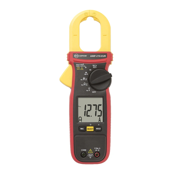
- Page 3 AMP-210 / AMP-210-EUR Series TRMS Clamp Multimeters 1.800.561.8187 information@itm.com www. .com...
- Page 4 AMP-210 / AMP-210-EUR Series TRMS Clamp Multimeters 1.800.561.8187 information@itm.com www. .com...
- Page 5 MAX: MIN: AVG: µF: µA: CAT III 1.800.561.8187 information@itm.com www. .com...
- Page 6 Measurement Category III (CAT III) 1.800.561.8187 information@itm.com www. .com...
- Page 7 1.800.561.8187 information@itm.com www. .com...
- Page 8 Press SELECT button to select the alternative SELECT / measurement function on the rotary switch. Press SELECT button > one second to turn ON or to turn OFF LCD backlight. LCD backlight automatically turns off after approximately 32 seconds. 1.800.561.8187 information@itm.com www.
- Page 9 HOLD / ZERO Press HOLD to freeze the display reading ( displayed) and releases the reading when pressed a second time. Press ZERO (HOLD) > one second to clear last reading from the display ( is displayed) and establish a baseline for applicable selected functions. DC-Zero mode for dc and ac+dc currents.
- Page 10 Note: Non-Contact Voltage Detection: 1.800.561.8187 information@itm.com www. .com...
- Page 11 To avoid electrical shock and injury: Remove Test Leads before making current measurements. Do not hold the Meter anywhere beyond the tactile barrier. Do not use the Meter to measure currents above the maximum rated frequency (400Hz). Circulating currents may cause the magnetic circuits of the Jaws reach hazardous excessive temperatures.
- Page 12 During current measurement keep the jaws away from other current- carrying devices such as transformers, motors or energized wires, as they may negatively influence accuracy of the measurement. To avoid electrical shock and injury: Remove Test Leads before making current measurements. Do not hold the Meter anywhere beyond the tactile barrier.
- Page 13 During current measurement keep the jaws away from other current- carrying devices such as transformers, motors or energized wires, as they may negatively influence accuracy of the measurement. 1.800.561.8187 information@itm.com www. .com...
- Page 14 To avoid false readings that can lead to electrical shock and injury, de- energize the circuit before taking the measurement. To avoid electrical shock when testing resistance/continuity/diode in a circuit, make sure the power to the circuit is turned off and all capacitors are discharged.
- Page 15 To avoid electrical shock and injury: When testing capacitor in a circuit, make sure the power to the circuit is turned off and all capacitors are discharged. When measuring temperature, DO NOT apply the temperature probe to any live conductive parts. Capacitance Temperature The Meter measures temperature in either Celsius (°C) or Fahrenheit (°F).
- Page 16 Correct rotation detection relies on solid signal connection to all three test lead terminals simultaneously. Any loose connection will lead to detection failure and false indication. To verify signal connection and the correct rotation indication, swap any of two signal connections l to check for indication of reverse movement.
- Page 17 Normal mode for the MAINS circuit: Using the Beeper feature on & mode: 1.800.561.8187 information@itm.com www. .com...
- Page 18 ° ° ° ° ° ° ° ° ° ° 1.800.561.8187 information@itm.com www. .com...
- Page 19 ° ° Input Impedance: Frequency: Input Impedance: Frequency: Input Impedance: Response: Audible Threshold: Response time: 1.800.561.8187 information@itm.com www. .com...
- Page 20 Open Circuit Voltage: Test Current: Open Circuit Voltage: -40.0 °C to -10.0 °C ±(1% + 1.5 °C) > -10 °C to 99.9 °C ±(1% + 0.8 °C) 100 °C to 400 °C ±(1% + 1 °C) -40.0 °F to 14.0 °F ±(1% + 3.0 °F) °F °F...
- Page 21 Frequency: 1.800.561.8187 information@itm.com www. .com...
- Page 22 Accuracy: measurement: Voltage Range: Frequency Range: measurement: Voltage Range: Frequency Range: Indication: Detection frequency: Detection antenna: 1.800.561.8187 information@itm.com www. .com...
- Page 23 To avoid shock, injury, or damage to the Meter, disconnect test leads before opening case. Replacing BATTERY follow below steps: 1.800.561.8187 information@itm.com www. .com...
Need help?
Do you have a question about the AMP-210 and is the answer not in the manual?
Questions and answers