
Summary of Contents for Global JUNO-NET
- Page 1 JUNO-NET Fire Alarm Control Panel OPERATION & MAINTENANCE MANUAL REVISION 0.7a 16-04-2004...
-
Page 2: Table Of Contents
JUNO-NET CONTENTS OPERATION SECTION 1 - Description of the fire control panel fascia..........Alarm....................Reset the system................... Sound and silence the alarms..............Read the Fire, Fault, Test and Disabled queues.......... Active Delays..................Lamp Test.................... Perform a fire drill................. Caretaker Test Mode................ -
Page 3: Operation
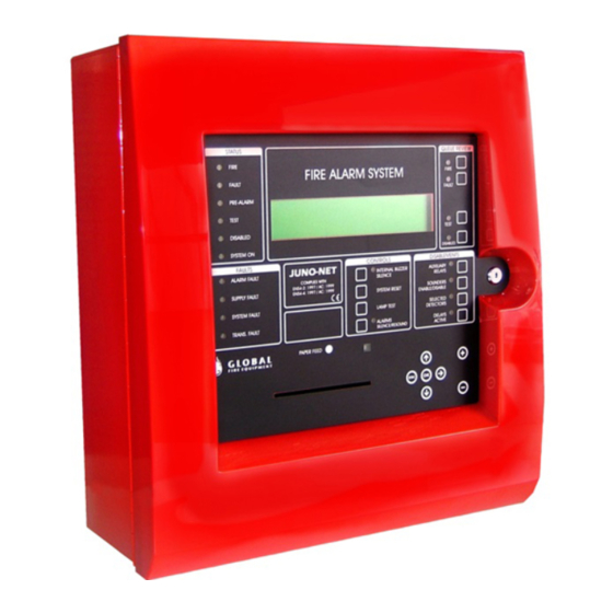
SECTION 1 JUNO-NET OPERATION 1.1 DESCRIPTION OF THE FIRE CONTROL PANEL FASCIA STATUS QUEUE REVIEW FIRE FIRE ALARM SYSTEM FIRE FAULT FAULT PRE-ALARM TEST LCD DISPLAY TEST DISABLED ALARM DISPLAY SYSTEM ON DISABLED FAULTS CONTROLS DISABLEMENTS JUNO-NET ALARM FAULT AUXILIARY... - Page 4 OPERATION JUNO-NET 1.1 DESCRIPTION OF THE FIRE CONTROL PANEL FASCIA (continued...) FIRE BRIGADE ACKNOWLEDGED: If the LED is AMBER it indicates that the transmission has been acknowledged. ALARM SILENCE : Pressing this button will silence all alarm sounders and buzzers during a FIRE condition as well as all buzzers during a FAULT condition.
-
Page 5: Alarm
OPERATION JUNO-NET 1.2 ALARM If the fire alarm control panel signals an ALARM the following events will take place: The sounders, I/O modules and other outputs will operate in accordance with their programming. At the fire control panel, the STATUS - FIRE will illuminate RED. -
Page 6: Reset The System
JUNO-NET OPERATION 1.3 RESET THE SYSTEM This procedure should be used if: STATUS QUEUE REVIEW There has been an alarm and the alarm FIRE FIRE ALARM SYSTEM FIRE condition no longer exists. FAULT FAULT PRE-ALARM LCD DISPLAY TEST There has been a fault and the fault condition... -
Page 7: Read The Fire, Fault, Test And Disabled Queues
JUNO-NET OPERATION 1.5 READ THE FIRE, FAULT, TEST AND DISABLED QUEUES Fire, fault, test, and disabled messages are shown on the LCD display. The LCD has a limited display area. If more messages exist than can be shown on the LCD display the FIRE, FAULT, TEST or DISABLED LEDs illuminate on the QUEUE REVIEW area of the fascia. -
Page 8: Active Delays
JUNO-NET OPERATION 1.6 ACTIVE DELAYS STATUS QUEUE REVIEW FIRE FIRE ALARM SYSTEM FIRE FAULT FAULT PRE-ALARM LCD DISPLAY TEST TEST DISABLED ALARM DISPLAY SYSTEM ON DISABLED FAULTS CONTROLS DISABLEMENTS JUNO-NET ALARM FAULT AUXILIARY ALARM SILENCE RELAYS MANUFACTURED TO THE SUPPLY FAULT... -
Page 9: Lamp Test
JUNO-NET OPERATION 1.7 LAMP TEST This tests that all LEDs on the fascia are functioning, that the buzzer sounds properly and that the LCD display is fully functional. STATUS QUEUE REVIEW FIRE FIRE ALARM SYSTEM FIRE FAULT FAULT PRE-ALARM LCD DISPLAY... -
Page 10: Perform A Fire Drill
JUNO-NET OPERATION 1.8 PERFORM A FIRE DRILL To start the fire drill press the SOUND ALARMS button The following will occur: STATUS QUEUE REVIEW All sounders turn on FIRE FIRE ALARM SYSTEM FIRE FAULT FAULT PRE-ALARM The SOUND ALARMS illuminates RED... -
Page 11: Caretaker Test Mode
OPERATION JUNO-NET 1.9 CARETAKER TEST MODE (One-Man Walk-Through Test) Entry and Exit of Caretaker Test Mode Press the QUEUE REVIEW - TEST button first, then the CONTROLS - LAMP TEST button momentarily. (The FAULTS - PROC FAULT LED will light momentarily, this is OK). - Page 12 OPERATION JUNO-NET 1.9 CARETAKER TEST MODE (continued...) Logging Individual detector tests are not logged (they would fill the log very quickly) Entry to Caretaker Test Mode is logged Devices Under Test All detectors and callpoints in all Zones will be put into test mode...
-
Page 13: Disablements
JUNO-NET OPERATION 1.10 DISABLEMENTS STATUS QUEUE REVIEW FIRE FIRE ALARM SYSTEM FIRE FAULT FAULT PRE-ALARM LCD DISPLAY TEST TEST DISABLED ALARM DISPLAY SYSTEM ON DISABLED FAULTS CONTROLS DISABLEMENTS JUNO-NET ALARM FAULT AUXILIARY ALARM SILENCE RELAYS MANUFACTURED TO THE SUPPLY FAULT... -
Page 14: Auxiliary Relays
JUNO-NET OPERATION 1.10 DISABLEMENTS (continued...) 1.10.2 AUXILIARY RELAYS The AUXILIARY RELAYS DISABLEMENT button enables and disables all relay and I/O module outputs. This means that those outputs will remain unchanged if a fire or fault occurs. The outputs that are controlled by this button include the normally energised FAULT relay, the FAULT I/O group, the EVAC relay as well as the I/O modules fitted to the analogue loops and, of course, the auxiliary relays. -
Page 15: If The Panel Displays A Fault
JUNO-NET OPERATION 1.11 IF THE PANEL DISPLAYS A FAULT If the system detects a fault, the STATUS - FAULT will light up AMBER. STATUS QUEUE REVIEW FIRE FIRE ALARM SYSTEM FIRE FAULT FAULT CALL THE MAINTENANCE ENGINEER PRE-ALARM LCD DISPLAY... -
Page 16: Maintenance
SECTION 2 JUNO-NET MAINTENANCE 2.1 PRINTER PAPER REPLACEMENT This procedure describes how to replace the paper when it runs out. Use of any paper not supplied by the manufacturer of this fire alarm control panel may result in shortened printer life and/or fading prints. Do not leave the paper in bright sunlight for long periods. -
Page 17: Sim Card Replacement
TAKE SUITABLE ESD PRECAUTIONS WHEN REMOVING OR INSTALLING PRINTED ENSURE THAT THE POWER IS TURNED OFF CIRCUIT BOARDS. SIM CARD JUNO-NET MOTHERBOARD (BACK VIEW) SIM CARD CONNECTOR DISPLAY The SIM CARD is mounted on the back of the main board. -
Page 18: Main Control Board Fuse
TAKE SUITABLE ESD PRECAUTIONS WHEN 2.3 MAIN BOARD CONTROL FUSES REMOVING OR INSTALLING PRINTED CIRCUIT BOARDS. The location, function and rating of the fuse on the main control board is given below. JUNO-NET MOTHERBOARD (BACK VIEW) WARNING ALWAYS REMOVE POWER FROM THE DISPLAY PANEL BEFORE REPLACING FUSES. -
Page 19: Battery Voltage And Charger Checks
MAINTENANCE JUNO-NET 2.6 BATTERY VOLTAGE AND CHARGER CHECKS On the main panel and sub-panels (if fitted) measure the battery voltage. This should be 28.5V +/- 0.2V. Switch off the primary supply and check that the battery voltage does not drop significantly. Carry out a test on a detector or manual callpoint with the primary supply disconnected to ensure that the batteries are healthy. -
Page 20: Use Of Programming Functions For Maintenance
MAINTENANCE JUNO-NET 2.7 USE OF PROGRAMMING FUNCTIONS FOR MAINTENANCE The following programming functions can be used to check that the panel is operating correctly. Note that to use these functions the installer needs to have granted ‘User Access’ to the following functions. - Page 21 JUNO-NET MAINTENANCE 1-5 Read/Clear Autostart Count Every time the Main Panel has a Master Reset or it’s power is cycled the Autostart count is incremented. SYSTEM RESETs from the front panel button do not increment the Autostart count. 7-1 Device Count, Type & Value Use this function to check that all Sub-panels are present and that all devices are present.
- Page 22 JUNO-NET MAINTENANCE 7-3 Sounders on Test Activation This function allows you to choose an audible confirmation that a device has detected a fire. The audible confirmation consists of a 1 second period of sounder operation. The settings selected by this function are used by ‘7-4 Test Zones’...
- Page 23 JUNO-NET MAINTENANCE 7-6 Light LED on device This function is used to confirm the physical location of a specific detector. For each Sub-panel only one detector LED can be lit at any one time. Select the device and SWITCHED ON and press ENTER. The device will typically take a few seconds to respond.
-
Page 24: Getting Into Programming Mode
JUNO-NET MAINTENANCE 2.8 GETTING INTO PROGRAMMING MODE . Programming mode is accessed via the miniature infra-red keypad (IR Keypad) or by connecting a PC (PS2) keyboard to the Main Panel. It is also possible to upload and download settings to a PC but to do this you must first enter the panel programming mode. - Page 25 JUNO-NET MAINTENANCE Connecting A PS2 PC Keyboard To The Main Panel JUNO-NET MOTHERBOARD (BACK VIEW) QUAD UART J-NET-QUART: QUAD UART SIM CARD CONNECTOR STANDOFFS (4) FOR LOOPCARD LOOPCARD HEADER DISPLAY LOOPCARD HEADER MASTER RESET PRINTER CONNECTOR PS2 PC KEYBOARD ADAPTOR...
- Page 26 JUNO-NET MAINTENANCE The IR Keypad is typically the most convenient method to program the system. The sensor for the IR Keypad is just below the SOUND ALARMS button on the Main Panel and on a Repeater. Each time a key is pressed on the IR Keypad the Main Panel will beep.
- Page 27 JUNO-NET MAINTENANCE Logging In To enter programming mode you need to log in. The Main Panel must be powered up and must have initialised itself i.e. NOT be showing the ‘INITIALISING’ message. Press ENTER on the IR Keypad (or keyboard). You must now input your unique customer access code (supplied with the panel).
-
Page 28: Logbook
MAINTENANCE JUNO-NET 2.9 LOGBOOK In accordance with EN54 part 14, it is the user's responsibility to maintain a logbook and to record all events resulting from or affecting the system. The logbook should be kept in a place accessible to authorised persons (preferably near the control panel). -
Page 29: Event Data Sheet
MAINTENANCE JUNO-NET 2.10 EVENT DATA SHEET DATE DATE TIME EVENT ACTION REQUIRED INITIALS COMPLETED OPERATION & MAINTENANCE MANUAL REVISION 0.7a 16-04-2004...
Need help?
Do you have a question about the JUNO-NET and is the answer not in the manual?
Questions and answers