
Related Manuals for A-Maize-Ing Heat NRP620-9


Summary of Contents for A-Maize-Ing Heat NRP620-9
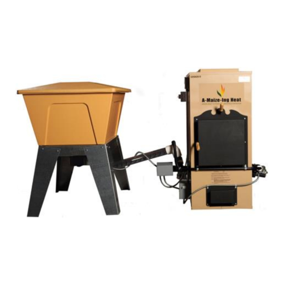
- Page 1 INSTALLATION MANUAL MODEL NRP620-9 FURNACE MODEL 14 BIN 899 South Prairie Lane - P.O. Box 500 Marshfield, MO 65706 PHONE 417-859-6067 FAX 417-859-2109...
- Page 2 This page intentionally left blank NRPIM620-9-20131212 Rev 1 Page 2 of 24...
-
Page 3: Table Of Contents
Table of Contents SAFETY INSTRUCTIONS........................4 INSTALLATION AND LOCATION CONSIDERATIONS................5 Installation Configurations ......................5 Required Tools ..........................5 FURNACE CLEARANCES AND ACCESSIBILITY ................. 6 Combustion Air Requirements ......................7 Venting .............................. 8 Important Vent Installation Requirements ................... 8 Listed Chimney ..........................9 Masonry Chimney .......................... -
Page 4: Safety Instructions
SAFETY INSTRUCTIONS ALL INFORMATION ON THIS PAGE MUST BE READ AND UNDERSTOOD BEFORE INSTALLATION Do not install or use this appliance unless the instructions in this manual are read and understood. This appliance must be installed in accordance with all local codes. Installation must be performed by a qualified installer, according to federal, state, provincial any individual or firm that is engaged in and is and local codes. -
Page 5: Installation And Location Considerations
Installation Configurations IMPORTANT The A-Maize-Ing Heat ® furnace is for use as a primary heat source. This unit is not designed to be installed as an add-on furnace. If you plan to use the A-Maize-Ing Heat ® furnace in conjunction with another furnace, install safety measures to prevent air back feed from one furnace to the other. -
Page 6: Furnace Clearances And Accessibility
Front 30” Rear-most surface 18” The A-Maize-Ing Heat ® furnace can be installed on a combustible floor if a non-combustible material is placed directly under the ash removal door and chimney connector. The mat is to extend at least 16” in front of and 8” to each side of the ash removal drawer and 2” either side of the chimney connector. -
Page 7: Combustion Air Requirements
18” on either side and 18” from the back of the furnace to the wall. The A-Maize-Ing Heat ® furnace is for use as a primary heat source. The A-Maize-Ing Heat ® furnace should be installed with the metal hot air plenum connected to metal hot air duct work and metal cold air return plenum joined to return air system. -
Page 8: Venting
Canadian installation may also use a 6” (minimum) metal flue pipe using sheet metal screws. Do not connect the A-Maize-Ing Heat ® furnace to any chimney flue servicing any other heating appliance, as recommended by the Nation Fire Prevention Association. All chimney connections must meet the approval of the local building inspector and fire marshal and conform to all local, state, provincial and national codes. -
Page 9: Listed Chimney
The following procedure for measuring and setting the proper chimney draft is probably the most important installation procedure to follow for the proper operation of the A-Maize-Ing Heat ® furnace. The A-Maize-Ing Heat ® furnace requires 0.02-0.04 inches water column draft (chimney draft) on low fire, to assure proper operation. - Page 10 NRPIM620-9-20131212 Rev 1 Page 10 of 24...
- Page 11 NRPIM620-9-20131212 Rev 1 Page 11 of 24...
-
Page 12: Furnace Unpacking And Set Up
FURNACE UNPACKING AND SET UP Your furnace was shipped from the factory with a “FURNACE PACKAGE” packing list. That document includes the part number and serial number. Locate that list and check the contents of the packaging to ensure all items were delivered. The items you will have are in the list below. FURNACE HOPPER HOPPER LID... - Page 13 NRPIM620-9-20131212 Rev 1 Page 13 of 24...
-
Page 14: Storage Bin
STORAGE BIN After removal of shipping container, position storage bin, on storage bin base, at desired angle for installation. For bolt together - fabricated metal hopper stand, see page 22. Install auger assembly by sliding auger boot (with clamp) under bin outlet; align elbow on bin auger tube directly over furnace fuel inlet. -
Page 15: Vibrator Mounting Instructions
VIBRATOR MOUNTING INSTRUCTIONS 1. Drill two 3/16” mounting holes 2 inches apart in the center of the long angle of the hopper bin. (See figure 1) 2. Mount vibrator to the hopper using the holes drilled. Open face of J box facing away from hopper body. -
Page 16: Thermostat Wiring
THERMOSTAT WIRING Connect thermostat wires to “R” and “G” terminals located on the relay, mounted on the furnace control box. Note: There is also a “C” terminal on the relay. Positively identify these terminals before connecting the thermostat wire. Connecting a thermostat wire to the “C” terminal will permanently damage the relay. -
Page 17: Electrical Wiring
ELECTRICAL WIRING WARNING For your personal safety, turn off electrical power at service entrance before making any electrical connections. All electrical work must conform to your local codes and ordinances or with the National Electrical Code. If you are not familiar with wiring and codes in general, have a competent electrician do this job. -
Page 18: Burner Lighting
BURNER LIGHTING NOTE: If the burner has been used, all leftover ash and clinkers must be thoroughly removed from the burner pot before following the lighting instructions. **IMPORTANT** On the initial lighting of the furnace, add approximately 2-3 cups of biomass fuel to the hopper. As the fuel feeds into the auger, add only small amounts until the fire is established and the feeding system is working properly. -
Page 19: Operation
OPERATION After the fire has been established in the burner pot and operating temperature has been reached (See burner lighting pg. 18) you need only to set the thermostat to the desired temperature. The thermostat will turn the furnace bin auger motors and combustion blower, on and off, to sustain the desired temperature. -
Page 20: Clinker Buildup
CLINKER BUILDUP The A-Maize-Ing Heat ® furnace feeds biomass fuel into the bottom of the burner, therefore creating the most efficient fuel consumption. The residual ash and clinkers are then spilled over the top of the burner ring, falling into the ash pan below. This process essentially cleans the burner chamber. -
Page 21: Power Failure Considerations
The low fire timer is located inside the electrical box where the On/Off/Start toggle switch is located. The Variable Btu timer is set to 15 seconds “ON” and 15 seconds “OFF”. The furnace should run for 24 hours before adjustments are made to ensure the unit temperature is stable. This furnace is equipped with an automatic/manual fan switch. -
Page 22: Storage Bin - Model 14
Storage Bin - Model 14 KEY # PART NUMBER PART DESCRIPTION PART DESCRIPTION 7520 BIN LID 7500 BIN CAVITY 7510 BIN BASE NRPIM620-9-20131212 Rev 1 Page 22 of 24... - Page 23 This page intentionally left blank NRPIM620-9-20131212 Rev 1 Page 23 of 24...
- Page 24 899 South Prairie Lane - P.O. Box 500 Marshfield, MO 65706 PHONE 417-859-6067 FAX 417-859-2109 NRPIM620-9-20131212 Rev 1 Page 24 of 24...
Need help?
Do you have a question about the NRP620-9 and is the answer not in the manual?
Questions and answers