
Related Manuals for A-Maize-Ing Heat LDJ620-9


Summary of Contents for A-Maize-Ing Heat LDJ620-9
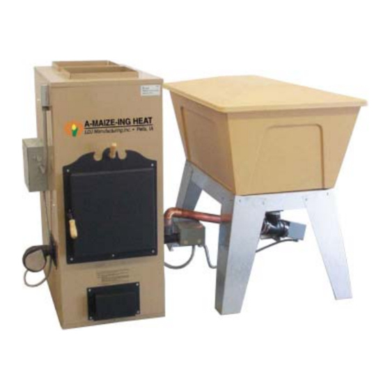
- Page 1 Model LDJ620-9 Furnace Model LDJ620-10 Furnace Model 14 Bin LDJ620_E01_R03_2006.03...
- Page 2 Furnace tested and certified by Underwriters Laboratories A-MAIZE-ING HEAT®, and A-MAIZE-ING HEAT® Logo are registered trademarks of LDJ Manufacturing, Inc. in the U.S. and/or other countries. No part of this manual may be reproduced in any form or by any means, electronic or mechanical, including photocopying, recording, or by any information storage and retrieval systems, without the express written consent of LDJ Manufacturing, Inc.
-
Page 3: Table Of Contents
Annual Maintenance ........... 19 2005.08.29 PTC Models LDJ620-9 and LDJ620-10... - Page 4 Mechanical / Electrical ..........23 Wiring Diagram: LDJ620-9 100,000 BTU Furnace ....... 24 Wiring Diagram: LDJ620-10 165,000 BTU Variable Rate Furnace .
-
Page 5: Warranty
LDJ Manufacturing, Inc. within 30 days of date of purchase, warranty claims on your unit ® may be denied. All warranty claims must be reported to the nearest A-MAIZE-ING HEAT dealer. I S C L A I M E R O F I A B I L I T Y The foregoing warranty constitutes the only warranty made by LDJ Manufacturing, Inc. -
Page 6: Safety Instructions
If you have any questions about this product or its installation, please contact us: Address LDJ Manufacturing, Inc. 1833 Hwy 163 Pella, Iowa 50219 Phone 641 • 620 • 9412 866 • 535 • 7667 641 • 620 • 8302 Website www.cornheat.com Email info@ldj-products.com Models LDJ620-9 and LDJ620-10 LDJ620_E01_R03_2006.03... -
Page 7: Installation And Location Considerations
O C A T I O N O N S I D E R A T I O N S ® Failure to install the A-MAIZE-ING HEAT furnace according to the guidelines and instructions contained within this manual may result in serious injury or death, property damage, or voiding of the warranty. -
Page 8: Combustion Air Requirements
• Any horizontal runs of connector pipe should A listed chimney must be rated for a solid-fuel have a minimum rise of 1/4" per foot of run to burning appliance and must comply with NFPA Models LDJ620-9 and LDJ620-10 LDJ620_E01_R03_2006.03... -
Page 9: Barometric Draft Controls
• Remove the other two screws from beneath the pallet. Step 4: Insert burner auger assembly (1) into burner auger tube (2). Step 3: Remove auger motor assembly and hardware package from ash pan drawer. LDJ620_E01_R03_2006.03 Models LDJ620-9 and LDJ620-10... -
Page 10: Unpacking And Setup - Storage Bin
Step 3: Position storage bin (4) on top of base (5). Make sure it is level and fitted against base at all corners. Step 2: Assemble base rails (1) and legs (2) together with sixteen 1/4"-20 x 1/2" bolts (3) and nuts. Models LDJ620-9 and LDJ620-10 LDJ620_E01_R03_2006.03... -
Page 11: Ducting
(9). Ducting IMPORTANT: The hot and cold air furnace ® connections to the A-MAIZE-ING HEAT furnace must not be less than 196 square inches. Any reduction in size of the connections will restrict air movement through the heat exchanger, resulting in overheating and operational problems with the furnace. -
Page 12: Chimney Vent
(3); do not fully tighten. Step 5: Check level of unit and tighten screws. Step 6: Drill a 1/4" hole into the flue connection pipe at a location between the furnace flue connection and the barometic draft control. Models LDJ620-9 and LDJ620-10 LDJ620_E01_R03_2006.03... - Page 13 Step 10: At the top of the unit, connect the hoses to it. • Connect the all white hose to the port marked HIGH (6). • Connect the white hose with the red line to the port marked LOW (7). LDJ620_E01_R03_2006.03 Models LDJ620-9 and LDJ620-10...
-
Page 14: Electrical Connections
• “R” - 24V power supply to thermostat • “W” - Heat signal from thermostat • “G” - Fan full time signal from thermostat • “Y” - A/C signal from thermostat • “C” - 24V common Models LDJ620-9 and LDJ620-10 LDJ620_E01_R03_2006.03... -
Page 15: Operation
(variable BTU output), always light it with the furnace set for 100,000 BTU output. After the furnace has run for thirty minutes, make the desired adjustments to the output. Refer to “Variable BTU Timer (LDJ620-10 only)” on page 17 for more information. LDJ620_E01_R03_2006.03 Models LDJ620-9 and LDJ620-10... - Page 16 (the auger motors will not turn until the furnace has reached operating temperature). Keep the switch in the START position for 5 to 10 minutes, or until you see a good even fire. Models LDJ620-9 and LDJ620-10 LDJ620_E01_R03_2006.03...
-
Page 17: Draft Adjustment
• High (black wire #1) All units are shipped from the factory set to the medium speed. The blower speed can be changed by accessing the 10"x10" control box on the left side of the furnace. Change blower LDJ620_E01_R03_2006.03 Models LDJ620-9 and LDJ620-10... -
Page 18: Clinker Buildup
Only adjust this opening when the combustion blower is running. Its adjustment should yield an intense fire that consumes the fuel at the same rate it is augered in. Models LDJ620-9 and LDJ620-10 LDJ620_E01_R03_2006.03... -
Page 19: Variable Btu Timer (Ldj620-10 Only)
BTU Output Green Arrow Red Arrow Combustion Gate 165,000 full to half open 132,000 full to half open 100,000 half to one quarter open 90,000 half to one quarter open 80,000 half to one quarter open LDJ620_E01_R03_2006.03 Models LDJ620-9 and LDJ620-10... -
Page 20: Maintenance
If the ashes are disposed of by burying in soil or otherwise dispensed, they should be retained in the closed container until all clinkers have thoroughly cooled. Models LDJ620-9 and LDJ620-10 LDJ620_E01_R03_2006.03... -
Page 21: Monthly Maintenance
“burning through”. • Inspect Motors Clean, oil, and inspect all blower and auger motors. This includes the burner fan (6), main blower fan (accessed through filter door), burner auger (7), and storage bin auger (8). LDJ620_E01_R03_2006.03 Models LDJ620-9 and LDJ620-10... -
Page 22: Troubleshooting
Fire goes out Chimney draft too high; clinkers are building up. Furnace inefficient and has too much Wet or dirty corn; not enough combustion air; not enough draft; not enough OFF time during low fire operation. Models LDJ620-9 and LDJ620-10 LDJ620_E01_R03_2006.03... -
Page 23: Poor Combustion
Corn cob or stalk is stuck in auger; furnace Clean/repair as necessary. has smoked back through the auger tube causing a build up of sticky residue. Burn auger has stopped, forcing hopper Clean/repair as necessary. auger to bind up. LDJ620_E01_R03_2006.03 Models LDJ620-9 and LDJ620-10... -
Page 24: Inefficient Operation And/Or Operating Too Hot
Not enough time between idle cycles Try changing timer — if set at 2 & 6, (indicated by fire pushing out the top). change to 2 & 7 (experimentation may be necessary). Models LDJ620-9 and LDJ620-10 LDJ620_E01_R03_2006.03... -
Page 25: Mechanical / Electrical
Blower for furnace operation (usu- Restart fire in burn pot. ally ‘MED’ motor speed) won’t run until fan control switch senses higher temperature. Fan relay contacts defective. Check fan relay. Blower motor defective. Replace blower motor. LDJ620_E01_R03_2006.03 Models LDJ620-9 and LDJ620-10... -
Page 26: Wiring Diagram: Ldj620-9 100,000 Btu Furnace
Heat Relay (HR) Bin Auger BLUE BLUE Motor 210°F Relay Furnace Auger Low Limit Motor Switch H-BK Closes on temp. rise H-BK Low Fire Timer/Relay (LF) START timer START Heat Control Switch Combustion Blower Motor Models LDJ620-9 and LDJ620-10 LDJ620_E01_R03_2006.03... -
Page 27: Wiring Diagram: Ldj620-10 165,000 Btu Variable Rate Furnace
High Fire Timer/Relay (HF) Low Limit Switch H-BK Bin Auger timer Motor Closes on temp. rise Furnace Auger H-BK Motor Low Fire START Timer/Relay (LF) timer START Heat Control Switch Combustion Blower Motor LDJ620_E01_R03_2006.03 Models LDJ620-9 and LDJ620-10... -
Page 28: Repair Parts
Burn Pot Auger Motor - 6 rpm — 3180 Lock Collar 1980 Bolt, 1/4" x 1/2" Self Tapping 3200 Burn Pot Auger Flighting 2070 Screw - Sheet Metal, #10 x 1-3/4" 3000 Auger Support 1410 6" x 6" Box Models LDJ620-9 and LDJ620-10 LDJ620_E01_R03_2006.03... -
Page 29: Hopper Bin Auger
Bin Auger Motor - 4 rpm — 1410 6" x 6" Box A-3070 Auger Support 5000 Lag Bolt - 1/4" x 1" 7530 Rubber Tee A-7540 Bin Auger Tube 1480 Conduit Fitting A-1550 Flex Conduit LDJ620_E01_R03_2006.03 Models LDJ620-9 and LDJ620-10... -
Page 30: Storage Bin - Model 14
Furnace Installation and Owners Manual Storage Bin - Model 14 Part Part Description Quantity Used Number LDJ620-9 LDJ620-10 7520 Bin Lid 7500 Bin Cavity 7510 Bin Base 7520 Shutoff Valve Models LDJ620-9 and LDJ620-10 LDJ620_E01_R03_2006.03... -
Page 31: Heat Exchanger
Quantity Used Number LDJ620-9 LDJ620-10 5700 Burner Heat Shield 5680 Heat Deflector 5660 Side Heat Shield 5640 Top Heat Shield A-5720 Heat Exchanger 2200 Wooden Handle 2040 Bolt - Shoulder, 5/16" x 1" 2020 Nut, 1/4" LDJ620_E01_R03_2006.03 Models LDJ620-9 and LDJ620-10... -
Page 32: Furnace Cabinet
Furnace Installation and Owners Manual Furnace Cabinet BACK FRONT Models LDJ620-9 and LDJ620-10 LDJ620_E01_R03_2006.03... - Page 33 Bank Side Panel 6240 Right Side Panel 6260 Left Side Panel A-6180 Furnace Top 6400 Trim Ring A-4260 Filter Rack 6300 Top Rear Panel A-6340 Filter Access Door 6420 Auger Hole Trim 2180 Fan Sealant, 1/2" thick LDJ620_E01_R03_2006.03 Models LDJ620-9 and LDJ620-10...
-
Page 34: Furnace Blower
Housing Supports - Both Sides 8122420 Vibration Pads — Screw - Hex Head, #10-24 x 7/8" — Nut, #10-24 — Screw - Hex Head, #10-24 x 3/4" — Screw - Hex Head, 1/4-20" x 1/2" 4M098 Motor Models LDJ620-9 and LDJ620-10 LDJ620_E01_R03_2006.03... - Page 35 Furnace Installation and Owners Manual This page intentionally left blank. LDJ620_E01_R03_2006.03 Models LDJ620-9 and LDJ620-10...
-
Page 36: Addendum
Furnace Installation and Owners Manual D D E N D U M Venting Information Models LDJ620-9 and LDJ620-10 LDJ620_E01_R03_2006.03... - Page 37 Furnace Installation and Owners Manual LDJ620_E01_R03_2006.03 Models LDJ620-9 and LDJ620-10...
-
Page 38: Barometric Draft Control Information
Seal with high temperature RTV silicone or high temperature foil tape UL listed for the temperature of the application. For proper settings and operation of the burner and the draft combustion testing instrumentation and draft gauges must be used. Models LDJ620-9 and LDJ620-10 LDJ620_E01_R03_2006.03... - Page 39 In mild weather when less heat is needed, or the fire is to be banked, close ash pit draft door partly or entirely. If desired, a check damper also can be used when banking the fire. Page 2 PN 02702600 Rev A 10/00 LDJ620_E01_R03_2006.03 Models LDJ620-9 and LDJ620-10...
-
Page 40: Ducting Information
Furnace Installation and Owners Manual Ducting Information Models LDJ620-9 and LDJ620-10 LDJ620_E01_R03_2006.03... - Page 41 Duct system installations that use the house structure or building framing (e.g., building cavities, closets, raised-floor air handler plenums, platform returns, wall stud spaces, panned floor joists) as supply or return ducts can be relatively LDJ620_E01_R03_2006.03 Models LDJ620-9 and LDJ620-10...
- Page 42 Consequently, if used, it must be leakage. Screws should be used to mechanically fasten all properly installed. joints. When located in an unconditioned space, sheet metal ducts must be insulated with either an interior duct liner or exterior insulation. Models LDJ620-9 and LDJ620-10 LDJ620_E01_R03_2006.03...
- Page 43 Use mastic, cork rope or tape, or caulk to permanently seal with installation or removal of the register. unused holes, seams, wire penetrations, and refrigerant and condensate line penetrations in the air handler cabinet. Use approved pressure-sensitive tapes to seal access panels. LDJ620_E01_R03_2006.03 Models LDJ620-9 and LDJ620-10...
- Page 44 Pressure-sensitive metallic tape with butyl adhesive (not cut the outer jacket. meeting UL Standard 181) can be used to seal metal-to-metal connections. Cork tape can be used to seal gaps where refrigerant lines penetrate the air handler unit cabinet. Models LDJ620-9 and LDJ620-10 LDJ620_E01_R03_2006.03...
- Page 45 Furnace Installation and Owners Manual LDJ620_E01_R03_2006.03 Models LDJ620-9 and LDJ620-10...
- Page 46 Furnace Installation and Owners Manual This page intentionally left blank. Models LDJ620-9 and LDJ620-10 LDJ620_E01_R03_2006.03...
Need help?
Do you have a question about the LDJ620-9 and is the answer not in the manual?
Questions and answers