
Related Manuals for WTI RSM-8


Summary of Contents for WTI RSM-8
- Page 1 WTI Part No. 13662 Rev. A RSM Series Remote Site Managers Models Covered: RSM-8 RSM-16 RSM-16DC RSM-32 RSM-32DC User's Guide...
-
Page 3: Warnings And Cautions
Warnings and Cautions: Installation Instructions Secure Racking If Secure Racked units are installed in a closed or multi-unit rack assembly, they may require further evaluation by Certification Agencies. The following items must be considered. 1. The ambient within the rack may be greater than room ambient. Installation should be such that the amount of air flow required for safe operation is not compromised. -
Page 4: Industry Canada
RSM Series; Remote Site Managers - User’s Guide FCC Part 15 Regulation This equipment has been tested and found to comply with the limits for a Class A digital device, pursuant to part 15 of the FCC Rules. These limits are designed to provide reasonable protection against harmful interference when the equipment is operated in a commercial environment. -
Page 5: Table Of Contents
Table of Contents Introduction ............1-1 Unit Description . - Page 6 RSM Series; Remote Site Managers - User’s Guide The Status Screens ........... . . 6-1 6.1.
- Page 7 List of Figures 2.1. Instrument Front Panel (Model RSM-8 Shown) ....... 2-1 2.2.
- Page 8 RSM Series; Remote Site Managers - User’s Guide...
-
Page 9: Introduction
1. Introduction The RSM-8, RSM-16, RSM-16DC, RSM-32 and RSM-32DC Remote Site Managers provide in-band and out-of-band access to RS-232 console ports and maintenance ports on UNIX servers, routers and any other network element that includes a serial console port. System administrators can access the RSM via TCP/IP network, using SSH or Telnet, or out-of-band via modem or local terminal. -
Page 10: Typographic Conventions
User's Guide, all of these units are referred to as the "RSM." Note however that these units differ as described below: • RSM-8: 8 Serial Ports, 100 to 240 VAC, 50/60 Hz, 5 Watts • RSM-16: 16 Serial Ports, 100 to 240 VAC, 50/60 Hz, 5 Watts •... -
Page 11: Unit Description
Remote CONNECTIONS CLEAR Site Manager Figure 2.1: Instrument Front Panel (Model RSM-8 Shown) CLEAR: Restarts the RSM without changing user-selected parameter settings. Note: When Clear is pressed, all ports will be disconnected. ON: Lights when AC Power is applied. -
Page 12: Instrument Back Panel (Model Rsm-8)
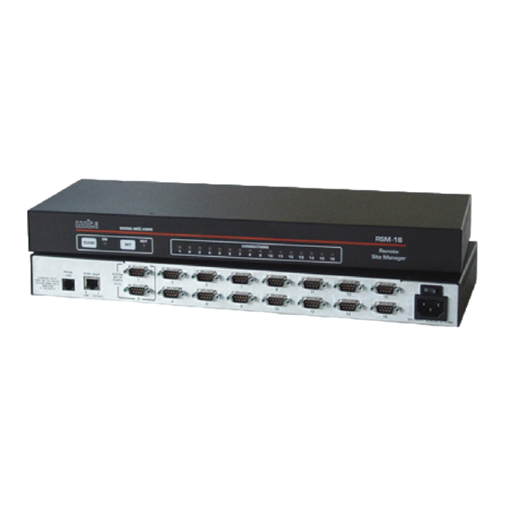
RSM Series; Remote Site Managers - User’s Guide PHONE 10/100BaseT SYSTEM SETUP PORTS LINE (DTE) LINK ACTIVITY Figure 2.2: Instrument Back Panel (Model RSM-8) PHONE 10/100BaseT SYSTEM LINE SETUP PORTS (DTE) LINK ACTIVITY Figure 2.3: Instrument Back Panel (Model RSM-16) -
Page 13: Back Panel
When connecting a PC or other DTE device use a null modem cable. • RSM-8 units include 8 Serial Ports. • RSM-16 and RSM-16DC units include 16 Serial Ports. • RSM-32 and RSM-32DC units include 32 Serial Ports. - Page 14 RSM Series; Remote Site Managers - User’s Guide...
-
Page 15: Getting Started
Refer to the safety precautions listed at the beginning of this User’s Guide and in Section 4, and then connect the unit to an appropriate power source. Note that RSM-8, RSM-16 and RSM-32 units are designed for 100 to 240 VAC, 50/60 Hz operation and feature an auto sensing power supply; while RSM-16DC and RSM-32DC models are designed for -48 VDC operation. -
Page 16: Communicating With The Rsm
RSM Series; Remote Site Managers - User’s Guide 3.2. Communicating with the RSM When properly installed and configured, the RSM will allow command mode access via Telnet, Web Browser, SSH client, modem, or local PC. However, in order to ensure security, both Telnet and Web Browser access are disabled in the default state. -
Page 17: The Port Status Screen - Text Interface (Rsm-8 Shown)
Free Pass | (undefined) Free Pass | (undefined) Free Pass | MODEM Free Modem | Enter /H for command menu. RSM> Figure 3.1: The Port Status Screen - Text Interface (RSM-8 Shown) Figure 3.2: The Home Screen - Web Interface... - Page 18 RSM Series; Remote Site Managers - User’s Guide Username / Password Prompt: A message will be displayed, which prompts you to enter your username (Login) and password.. The default username is "super" (all lower case, no quotes), and the default password is also "super".
- Page 19 User’s Guide for important information regarding advanced configuration capabilities and more detailed operation instructions. If you have further questions regarding the RSM unit, please contact WTI Customer Support as described in Appendix C.
- Page 20 RSM Series; Remote Site Managers - User’s Guide...
-
Page 21: Hardware Installation
4. Hardware Installation 4.1. Connecting Power to the RSM Unit The RSM is available in both AC and DC powered versions. When connecting AC or DC power to the RSM, proceed as follows: CAUTIONS: • Before attempting to install this unit, please review the warnings and cautions listed at the front of the user's guide. -
Page 22: Connecting The Network Cable
RSM Series; Remote Site Managers - User’s Guide 4.2. Connecting the Network Cable The Network Port is an RJ45, 10/100BaseT Ethernet Jack, for connection to a TCP/IP network. Note that the RSM features a default IP Address (192.168.168.168.) Providing that you are communicating with the unit from a node on the same subnet, this allows you to contact the RSM without first accessing command mode to assign an IP address. -
Page 23: Configuration
5. Configuration 5.1. Communicating with the RSM Unit In order to configure the RSM, you must first connect to the unit, and access command mode. Note that, the RSM offers two separate configuration interfaces; the Web Browser Interface and the Text Interface. In addition, the RSM also offers three different methods for accessing command mode;... - Page 24 RSM Series; Remote Site Managers - User’s Guide In order to use the Text Interface, your installation must include: • Access via Network: The RSM must be connected to your TCP/IP Network, and your PC must include a communications program (such as HyperTerminal.) •...
-
Page 25: The Port Status Screen (Text Interface; Rsm-8 Shown)
Modem | Enter /H for command menu. RSM> Figure 5.1: The Port Status Screen (Text Interface; RSM-8 Shown) Login / Password Prompt: A message will be displayed, which prompts you to enter a username (login name) and password. The default username is "super" (all lower case, no quotes), and the default password is also "super". -
Page 26: The Web Browser Interface
RSM Series; Remote Site Managers - User’s Guide Figure 5.2: The Home Screen (Web Browser Interface) 5.1.2. The Web Browser Interface The Web Browser Interface consists of a series of web forms, which can be used to select configuration parameters and enable/disable RSM operating functions, by clicking on radio buttons and/or entering text into designated fields. -
Page 27: System Setup Ports
Confi guration 5.2. System SetUp Ports Serial Ports 1 and 2 are reserved as SetUp Ports, and will always permit password protected access to Supervisor commands. Therefore, Ports 1 and 2 cannot be configured as Buffer Mode Port or Passive Mode Ports, because these port modes do not permit access to command mode. -
Page 28: The System Parameters Menu (Text Interface)
RSM Series; Remote Site Managers - User’s Guide SYSTEM PARAMETERS: 1. User Directory 2. Site-ID: 3. Real Time Clock: 06/03/2006 00:26:06 4. Invalid Access Lockout: 5. Audit Log: On - Without Syslog 6. Callback Security: On - Callback (Without Password Prompt) 7. -
Page 29: Defining System Parameters
Confi guration 5.4. Defining System Parameters The System Parameters menus are used to define the Site ID Message, set the system clock and calendar, and configure the Invalid Access Lockout feature and Callback feature. In the Text Interface, the System Parameters menu is also used to create and manage user accounts and passwords. -
Page 30: The Real Time Clock And Calendar
RSM Series; Remote Site Managers - User’s Guide • Audit Log: Enables and configures the Audit Log feature, as described in Section 5.4.3. (Default = On - Without Syslog.) • Callback Security: Enables / configures the Callback Security Function as described in Section 5.4.4. In order for this feature to function, a Callback number must also be defined for each desired user account as described in Section 5.6. - Page 31 Confi guration • NTP Enable: When enabled, the RSM will contact an NTP server (defined via the NTP IP Address prompts) once a day, and update its clock based on the NTP server time and selected Time Zone. (Default = Off.) Notes: •...
-
Page 32: The Invalid Access Lockout Feature
RSM Series; Remote Site Managers - User’s Guide 5.4.2. The Invalid Access Lockout Feature When properly configured and enabled, the Invalid Access Lockout feature will watch all login attempts made at all RSM ports. If a given port exceeds the selected number of invalid attempts, then that port will be automatically disabled for a user-defined length of time. -
Page 33: The Audit Log
Confi guration The Invalid Access menus allow you to select the following: • Lockout Enable: Enables/Disables the Invalid Access Lockout feature. (Default = On.) • Lockout Attempts: The number of invalid attempts required to activate the Invalid Access Lockout feature. (Default = 9.) •... -
Page 34: Callback Security
RSM Series; Remote Site Managers - User’s Guide 5.4.4. Callback Security The Callback function provides an additional layer of security when callers attempt to access command mode via modem. When this function is properly configured, modem users will not be granted immediate access to command mode upon entering a valid password;... - Page 35 Confi guration On - Callback ONLY (Without Password Prompt): Callbacks will ◆ be performed for user accounts that include a Callback Number, and the username/password prompt will not be displayed when the user’s modem answers. Accounts that do not include a Callback Number will not be able to access command mode via an RSM modem port.
-
Page 36: User Accounts
RSM Series; Remote Site Managers - User’s Guide 5.5. User Accounts Prior to accessing command mode or establishing a Telnet Direct Connection, you will be prompted to enter a username (login) and password. The username and password entered at login determine which port(s) you will be allowed to connect and what type of commands you will be allowed to execute. -
Page 37: Port Access
Confi guration In most cases, a password with Supervisor Access can be entered at any port, allowing the user to invoke Supervisor level commands. However, if you wish to completely deny a specific port’s access to Supervisor commands (even with a password that normally permits them), the Port Parameters menus can disable Supervisor commands at ports 3 and above, and the Network Port. -
Page 38: The Add User Menu (Text Interface; Rsm-8 Shown)
(undefined) (undefined) MODEM 5. Callback Phone #: Enter: #<CR> to select, <ESC> to return to previous menu ... Figure 5.5: The Add User Menu (Text Interface; RSM-8 Shown) Figure 5.6: The Add User Menu (Web Browser Interface; RSM-8 Shown) 5-16... -
Page 39: Viewing User Accounts
Confi guration 5.6.1. Viewing User Accounts The "View User Directory" option allows you to view details about each account, including the ports the account is allowed to access and whether or not the account is allowed to invoke Supervisor commands. The View User option will not display actual passwords, and instead, the password field will read either "defined"... -
Page 40: Modifying User Accounts
RSM Series; Remote Site Managers - User’s Guide • Port Access: Determines which port(s) this account will be allowed to create connections with. (Default = All Ports Off.) • Callback Number: Assigns a number that will be called when this user attempts to access command mode via modem at an RSM port, where the Callback Security Function has been enabled as described in Section 5.4.4. -
Page 41: Deleting User Accounts
Confi guration 5.6.4. Deleting User Accounts This function is used to delete individual user accounts. Note that the Delete User function is only available to users who have accessed command mode using a password that permits Supervisor Level commands. To delete an existing user account, proceed as follows: •... -
Page 42: Port Configuration Menu (Text Interface)
RSM Series; Remote Site Managers - User’s Guide PORT PARAMETERS #03: COMMUNICATION SETTING PORT MODE PARAMETERS 1. Baud Rate: 9600 21. Port Name: 2. Bits/Parity: 8-None 22. Port Mode: Passive 3. Stop Bits: 23. DTR Output: Pulse 4. Handshake: RTS/CTS 24. -
Page 43: Port Configuration
Up String, Reset String, and Initialization String. The Modem Mode is not available at the Network Port and is the default mode for the internal modem port (The Modem Port is Port 9 on RSM-8 units, Port 17 on RSM-16 and RSM-16DC units, and Port 33 on RSM-32 and RSM-32DC units.) -
Page 44: Rs232 Port Configuration Menus
RSM Series; Remote Site Managers - User’s Guide 5.7.2. RS232 Port Configuration Menus The Port Configuration Menus are used to select communications parameters and enable/disable options for each RS232 port. • Text Interface: Type /P n and then press [Enter] (Where n is the number or name of the desired RS232 Serial Port.) The Port Parameters menu will be displayed as shown in Figure 5.7. - Page 45 Confi guration General Parameters: • Supervisor Mode: Permits/denies port access to supervisor commands. When enabled (Permit), the port will be allowed to invoke supervisor commands, providing the unit is accessed using an account that permits them. If disabled (Deny), the port may not invoke Supervisor commands. (Default = Permit).
- Page 46 RSM Series; Remote Site Managers - User’s Guide • Inactivity Timeout: Enables and selects the Timeout Period for this port. If enabled, the port will disconnect when no additional data activity is detected for the duration of the timeout period. When the port is set for Any-to-Any Mode, Passive Mode, or Buffer Mode, the default setting is "Off."...
- Page 47 Confi guration Depending on the Port Mode selected, the RSM will also display the additional prompts listed in this section. In the Text Interface, these parameters are accessible via a submenu, which will only be active when the appropriate port mode is selected, and in the Web Browser Interface, fields will be "grayed out"...
- Page 48 RSM Series; Remote Site Managers - User’s Guide Network Services: • Direct Connect: Direct Connect allows users to access the RSM and automatically create a connection between the Network Port and a specific RS232 port by including the appropriate Telnet port number in the connect command (e.g.
- Page 49 Confi guration • Syslog: The Syslog feature is used to create records of each buffer event. As event records are created, they are sent to a Syslog Daemon, at an IP address defined via the Network Parameters menu. For more information, please refer to Section 9.
-
Page 50: Configuring The Internal Modem
Port Selector Menu. Use the Port Selector Menu, to select the Modem Port as follows: ▪ RSM-8 Units: Click on the down arrow to display the drop down menu, highlight port 9 and then click on the "Select Port" button. -
Page 51: Network Port Configuration Menu
Confi guration 5.7.3. Network Port Configuration Menu The Network Parameters Menus are used to select parameters and options for the Network Port and also allow you to implement IP Security features, which can restrict access based on the user’s IP Address. Although the Web Browser Interface and Text Interface allow definition of essentially the same parameters, parameters are arranged differently in the two interfaces. -
Page 52: Network Parameters Menu (Supervisor Mode Only)
RSM Series; Remote Site Managers - User’s Guide NETWORK PARAMETERS: COMMUNICATION SETTING SERVERS AND CLIENTS IP Address: 192.168.168.168 21. Telnet Access: Subnet Mask: 255.255.255.0 22. SSH Access: Gateway Addr: 207.212.30.1 23. Web Access: DHCP: 24. SYSLOG IP addr: (undefined) IP Security: 25. -
Page 53: Network Parameters Menu (Web Browser Interface)
Confi guration Figure 5.11: Network Parameters Menu (Web Browser Interface) Network Parameters In the Text Interface, these parameters are accessed via the Network Configuration menu (Figure 5.9.) In the Web Browser Interface, these parameters can be found by first clicking the "Network Configuration" link, and then Clicking the "Network Parameters"... - Page 54 RSM Series; Remote Site Managers - User’s Guide • Web Access: Enables/disables the Web Browser Interface. When disabled, users will not be allowed to contact the unit via the Web Browser Interface. (Default = Off.) • SSH Access: Enables/disables SSH communication with the RSM. (Default = On.) •...
-
Page 55: Network Port Parameters Menu (Web Browser Interface)
Confi guration Figure 5.12: Network Port Parameters Menu (Web Browser Interface) • Inactivity Timeout: Enables and selects the Inactivity Timeout period for the Network Port. If enabled, and the port does not receive or transmit data for the specified time period, the port will disconnect. (Default = 5 Minutes). - Page 56 RSM Series; Remote Site Managers - User’s Guide IP Security As described in Section 5.7.4, the IP Security function allows you to restrict command mode access based on the user’s IP address. In the Text Interface, IP Security parameters are defined via item 8 in the Network Configuration menu (Figure 5.9.) In the Web Browser Interface, these parameters are found by clicking the "Network Configuration"...
-
Page 57: Snmp Parameters Menu (Web Browser Interface)
Confi guration Figure 5.13: SNMP Parameters Menu (Web Browser Interface) SNMP Parameters In the Text Interface, SNMP parameters are found in the Network Configuration menu (Figure 5.9.) In the Web Browser Interface, SNMP parameters can be found by first clicking the "Network Configuration" link, and then clicking the "SNMP Parameters"... - Page 58 RSM Series; Remote Site Managers - User’s Guide TACACS Parameters To access the TACACS Configuration Menus, proceed as follows: • Text Interface: Type /N and press [Enter] to access the Network Configuration Menu. From the Network Configuration Menu, type 27 and press [Enter] to display the TACACS Configuration Menu.
- Page 59 Confi guration RADIUS Parameters To access the RADIUS Configuration Menus, proceed as follows: • Text Interface: Type /N and press [Enter] to access the Network Configuration Menu. From the Network Configuration Menu, type 28 and press [Enter] to display the RADIUS Configuration Menu. •...
-
Page 60: Implementing Ip Security
RSM Series; Remote Site Managers - User’s Guide 5.7.4. Implementing IP Security The RSM can restrict unauthorized IP addresses from establishing an inbound Telnet connection to the unit. This allows the user to grant Telnet access to only a specific group of IP addresses, or block a particular IP address. In the default state, the RSM accepts incoming IP connections from all hosts. -
Page 61: Ip Security Menu (Text Interface)
Confi guration IP SECURITY: CLIENT LIST FOR “hosts.allow” FILE: CLIENT LIST FOR “hosts.deny” FILE: Enter: #<CR> to select menu, <ESC> for previous menu ... Figure 5.14: IP Security Menu (Text Interface) Figure 5.15: IP Security Menu (Web Browser Interface) 5-39... -
Page 62: Adding Ip Addresses To The Allow And Deny Lists
RSM Series; Remote Site Managers - User’s Guide 5.7.4.1. Adding IP Addresses to the Allow and Deny Lists To add an IP Address to the Allow or Deny list, and begin configuring the IP Security feature, proceed as follows. Notes: •... -
Page 63: Linux Operators And Wild Cards
Confi guration 5.7.4.2. Linux Operators and Wild Cards In addition to merely entering a specific IP address or partial IP address in the Allow or Deny list, you may also use any standard Linux operator or wild card. In most cases, the only operator used is "EXCEPT" and the only wild card used is "ALL,"... -
Page 64: Ip Security Examples
RSM Series; Remote Site Managers - User’s Guide 5.7.4.3. IP Security Examples Mostly Closed: Access is denied by default and the only clients allowed, are those explicitly listed in the Allow list. To deny access to all clients except 192.255.255.192 and 168.112.112.05, the Allow and Deny lists would be defined as follows: •... -
Page 65: Copying Parameters To Several Rs-232 Ports (Text Interface Only)
Confi guration COPY PORT PARAMETERS: COMMUNICATION SETTING PORT MODE PARAMETERS 1. Baud Rate: 21. Port Name: 2. Bits/Parity: 22. Port Mode: 3. Stop Bits: 23. DTR Output: 4. Handshake: 24. Buffer Params: 25. Modem Params: GENERAL PARAMETERS NETWORK SERVICES 11. Supervisor Mode: 31. -
Page 66: Save User Selected Parameters
RSM Series; Remote Site Managers - User’s Guide Invoke the /CP command at the command prompt; the menu shown in Figure 5.16 will be displayed. The following options are available: Copy to All Ports: Type /CP [Enter]. Copy to a Range of Ports: Type /CP m-n [Enter]. Where m and n are port numbers that specify the desired range. -
Page 67: The Status Screens
Pass | (undefined) Free Pass | (undefined) Free Pass | (undefined) Free Pass | (undefined) Free Pass | MODEM Free Modem | Enter /H for command menu. RSM> Figure 6.1: Port Status Screen (Sample Data Shown - RSM-8 Unit Shown) -
Page 68: The Port Diagnostics Screen (/Sd)
RSM Series; Remote Site Managers - User’s Guide The Port Status Screen lists the following items: • Port: The Port Number. • Name: The user-defined name for each port. • Username: The username that was entered in order to access command mode via this port. -
Page 69: Port Diagnostics Screen (Rsm-8 Shown)
57.6K | 8N1 | RTS Modem | Enter /H for command menu. RSM> Figure 6.2: Port Diagnostics Screen (RSM-8 Shown) • Status: The connect status for each port. When the port is connected, this column will list the number of the ◆... -
Page 70: The Network Status Screen (/Sn)
RSM Series; Remote Site Managers - User’s Guide NETWORK STATUS: MAC Address: 00-09-9b-00-b7-fa PORT|TCP PORT|STATUS| USERNAME |PORT|TCP PORT|STATUS| USERNAME ---------------------------------------------------------------------------- 23|Active|super |N17 | | Free | 23|Active|super |N18 | | Free | | Free | |N19 | | Free | | Free | |N20 | | Free |... -
Page 71: The Port Parameters Screens (/W)
The Status Screens • Status: The status for each TCP port. If the Status Column reads "Active," this indicates the port has ◆ accessed command mode. If this Telnet session is connected to an RS232 Port, this column will ◆ read "C-nn,"... -
Page 72: Port Parameters Screen (Rs232 Port Shown)
RSM Series; Remote Site Managers - User’s Guide PORT PARAMETERS #03: COMMUNICATION SETTING PORT MODE PARAMETERS 1. Baud Rate: 9600 21. Port Name: 2. Bits/Parity: 8-None 22. Port Mode: Passive 3. Stop Bits: 23. DTR Output: Pulse 4. Handshake: RTS/CTS 24. -
Page 73: Operation
7. Operation This section discusses the procedures for connecting and disconnecting ports, and describes the various port modes. Note: The Web Browser Interface cannot be used to connect or disconnect ports. In order to connect or disconnect ports, you must access command mode via the Text Interface. - Page 74 RSM Series; Remote Site Managers - User’s Guide To Connect ports, proceed as follows: Access command mode via the Text Interface. Invoke the /C command to connect the desired ports. Resident Connect: To connect your resident port to another port, type /C xx [Enter].
-
Page 75: Disconnecting Ports
Operation 7.1.1.2. Disconnecting Ports There are three different methods for disconnecting ports, the Resident Disconnect, the Third Party Disconnect, and the No Activity Timeout. Providing the Timeout feature is enabled, a No Activity Timeout will disconnect resident ports or third party ports. Note: The "DTR Output"... - Page 76 RSM Series; Remote Site Managers - User’s Guide The /D (Disconnect) command can only be invoked by accounts and ports that permit Supervisor commands. The /D command can specify both connected ports, or either of the two ports. For example, if Port 1 is your resident port, any of the following commands can be used to disconnect Port 3 from Port 4: /D 3 4 [Enter] /D 3 [Enter]...
-
Page 77: Defining Hunt Groups
Operation 7.1.2. Defining Hunt Groups A Hunt Group creates a situation where the RSM will scan a group of similarly named ports and connect to the first available port in the group. Hunt Groups are created by assigning identical or similar names to two or more ports. Hunt Groups can be defined using Any-to-Any, Passive, Buffer, or Modem Mode Ports. -
Page 78: Passive Mode
RSM Series; Remote Site Managers - User’s Guide Hunt Group Example 1: Ports 1 and 2 are Modem Mode ports, and modems are installed at both ports. Port 1 is named "MODEM1" and Port 2 is named "MODEM2". Your resident port is Port 4. To connect to the first available Modem, type /C MODEM* [Enter]. -
Page 79: Buffer Mode
Operation 7.3. Buffer Mode The Buffer Mode allows collection of data from various devices without the requirement that all devices use the same communication parameters (e.g. baud rate, parity, etc.). In addition, Buffer Mode ports can also be configured to support the SYSLOG and SNMP Trap functions, as described in Sections 9 and 10. -
Page 80: Port Buffers
RSM Series; Remote Site Managers - User’s Guide To clear data from any port buffer (with or without reading it first), access command mode via the text interface, using an account and port that permit Supervisor commands, then issue the /E (Erase Buffer) command using the following format: /E xx [Enter] Where xx is the number of the port buffer to be cleared. -
Page 81: Modem Mode
Operation 7.4. Modem Mode The Modem Mode provides features specifically related to modem communication. A Modem Mode Port can perform all functions normally available in Any-to-Any Mode. The Modem Mode is available to all RSM ports except the Network Port, and is the default port mode at the Internal Modem port. - Page 82 RSM Series; Remote Site Managers - User’s Guide 7-10...
-
Page 83: Telnet & Ssh Functions
8. Telnet & SSH Functions 8.1. Network Port Numbers Whenever an inbound Telnet or SSH session connects to an RSM RS232 Port, the Port Status Screen and Port Diagnostics Screen will indicate that the RS232 port is presently connected to Port "Nn" (where "N" indicates a network connection, and "n"... -
Page 84: The Direct Connect Feature
RSM Series; Remote Site Managers - User’s Guide 8.3. The Direct Connect Feature The Direct Connect feature allows you to initiate a Telnet, SSH or Raw Socket session with the RSM and make an immediate connection to a specific RS232 Port of your choice, without first being presented with the command interface. -
Page 85: Configuration
Telnet & SSH Functions 8.3.2. Configuration The Direct Connect Function is configured on a per port basis using the Port Configuration Menus (/P nn), item 13, "Direct Connect". The following options are available: Direct Connect OFF: Direct Connect disabled at this port. (Default) Direct Connect ON - NO PASSWORD: The Direct Connect feature is enabled at this port, but no password is required in order to connect to the port. -
Page 86: Connecting To An Rs232 Port Using Direct Connect
Connecting to an RS232 Port using Direct Connect Direct Connect TCP port numbers are as follows: Standard Telnet Direct Connection (with Password): RSM-8: • Serial Ports: TCP port numbers 2101 through 2108. • Internal Modem Port: TCP port number 2109. - Page 87 Telnet & SSH Functions Raw Socket Direct Connection (with Password): RSM-8: • Serial Ports: TCP port numbers 3101 through 3108. • Internal Modem Port: TCP port number 3109. RSM-16 & RSM-16DC: • Serial Ports: TCP port numbers 3101 through 3116.
-
Page 88: Terminating A Direct Connect Session
RSM Series; Remote Site Managers - User’s Guide 8.3.4. Terminating a Direct Connect Session To terminate a Direct Connect session, use the client program’s "disconnect" feature. The following will occur immediately upon a client initiated disconnect: The Network port is disconnected from the RS232 Port. The Network session is terminated. -
Page 89: The Syslog Feature
9. The Syslog Feature The Syslog feature can create time-stamped log records of each buffer event. As these event records are created, they are sent to a Syslog Daemon, located at an IP address defined via the Network Parameters menu. Note: •... - Page 90 RSM Series; Remote Site Managers - User’s Guide Port Parameters Menu: Access the Port Parameters Menu for the desired port as described in Section 5.7.2, and then set the following parameters: Port Mode: Set the Port Mode to "Buffer." Syslog Function: Enable the Syslog Function. The Syslog Function allows you to select either "On - Not Connected"...
-
Page 91: Criteria For Generating A Syslog Message
The Syslog Feature 9.2. Criteria for Generating a Syslog Message Once the RSM is properly configured, Syslog messages will be generated as follows: Data Terminated by NULL Character: Syslog will generate a message whenever a properly configured Buffer Mode Port receives data or text terminated by a NULL character (0x00). -
Page 92: Testing Syslog Configuration
RSM Series; Remote Site Managers - User’s Guide 9.3. Testing Syslog Configuration After you have configured the RSM as described in Section 9.1, the /TEST command can be used to make certain that the function is properly set up. To test the Syslog function, type /TEST, press [Enter], then follow the instructions in the resulting submenu. -
Page 93: Snmp Traps
10. SNMP Traps SNMP is an acronym for "Simple Network Management Protocol". The SNMP Trap function allows Buffer Mode Ports to send a message to two different SNMP Managers, indicating the amount of data currently stored in buffer memory. Note: •... -
Page 94: Snmp Trap Message
RSM Series; Remote Site Managers - User’s Guide Network Parameters Menu: Access the Network Parameters Menu as described in Section 5.7.3. Set the following: Enable: SNMP Access must be enabled in order for SNMP traps to function. SNMP Contact: (Optional.) SNMP Location: (Optional.) SNMP Managers 1 and 2: Consult your network administrator to determine the IP address(es) for the SNMP Manager(s), then... -
Page 95: Testing The Snmp Trap Function
SNMP Traps 10.4. Testing the SNMP Trap Function After you have finished setting up the SNMP Trap function, it is recommended to test the configuration to ensure that it is working correctly. To test configuration of the SNMP Trap function, proceed as follows: Configure the SNMP Trap function as described in Section 10.1. - Page 96 RSM Series; Remote Site Managers - User’s Guide 10-4...
-
Page 97: Saving And Restoring Configuration Parameters
11. Saving and Restoring Configuration Parameters Once the RSM is properly configured, parameters can be downloaded and saved as an ASCII text file. Later, if the configuration is accidentally altered, the saved parameters can be uploaded to automatically reconfigure the unit without the need to manually assign each parameter. -
Page 98: Restoring Saved Parameters
RSM Series; Remote Site Managers - User’s Guide The RSM will send a series of ASCII command lines which specify currently selected parameters. The last line of the file should end with a "/G-00" command. When the download is complete, press [Enter] to return to the command prompt. -
Page 99: Upgrading Rsm Firmware
Obtain the update file. Firmware modifications can either be mailed to the customer on a CDR, or downloaded from WTI. Place the upgrade CDR in your disk drive or copy the file to your hard drive. Access Text Interface command mode via Serial Port, Telnet or SSH client session, using a username/password and port that permit Supervisor commands. - Page 100 (Default = 192.168.168.168) or access command mode via Serial Port 1 or 2 or via Modem. When firmware upgrades are available, WTI will provide the necessary files via download or mailed CDR. At that time, an updated Users Guide or addendum will also be available.
-
Page 101: Command Reference Guide
13. Command Reference Guide 13.1. Command Conventions Most commands described in this section conform to the following conventions: • Text Interface: Commands discussed in this section, can only be invoked via the Text Interface. These commands cannot be invoked via the Web Browser Interface. -
Page 102: Command Summary
RSM Series; Remote Site Managers - User’s Guide 13.2. Command Summary Command Availability Function Command Syntax Supervisor Non-Super. Resident Disconnect /A [search text] [Enter] Display Audit Log /C <x> [x] [Enter] Connect X /CP [Enter] Copy RS232 Port Parameters /CP [x,y,z] [Enter] /CP [x-z] [Enter] /D[/Y] <x>... -
Page 103: Command Set
Command Reference Guide 13.3. Command Set This Section provides information on all Text Interface commands, sorted alphabetically by command. Resident Disconnect Sequence The Resident Disconnect Sequence is used to disconnect your resident port from another port as described in Section 5.7. Although the default Resident Disconnect Sequence is ^X ([Ctrl] plus [X]), the command can be redefined via the Port Configuration Menus as described in Section 5.7.2. - Page 104 RSM Series; Remote Site Managers - User’s Guide Connect Establishes a bidirectional connection between two ports. For more information, see Section 7.1. There are two types of connections: • Resident Connect: If the /C command specifies only one port, your resident port will be connected to the specified port.
- Page 105 Command Reference Guide Third Party Disconnect Invoke the /D command at your resident port to disconnect two other ports. Note that the /D command cannot disconnect your resident port. Availability: Supervisor Only Format: /D[/Y] <x> [x] [Enter] Where: (Optional) suppresses the "Sure?" prompt. Is the number or name of the port(s) to be disconnected.
- Page 106 RSM Series; Remote Site Managers - User’s Guide Set System Parameters Displays a menu which is used to define the Site ID message, create user accounts, set the system clock, and configure and enable the Invalid Access Lockout feature. Note that all functions provided by the /F command are also available via the Web Browser Interface in the "System Parameters"...
- Page 107 Command Reference Guide Display Site ID Displays the Site I.D. message. Availability: Supervisor / Non-Supervisor Format: /J [Enter] Response: Displays Site I.D. Message. Send SSH Key Instructs the RSM to provide you with a public SSH key for validation purposes. This public key can then be provided to your SSH client, in order to prevent the SSH client from warning you that the user is not recognized when you attempt to create an SSH connection.
- Page 108 RSM Series; Remote Site Managers - User’s Guide Set RS232 Port Parameters Displays a series of menus used to select options and parameters for the RS232 ports. Note that all functions provided by the /P command are also available via the Web Browser Interface in the "Serial Port" menu. Section 5.7.2 describes the procedure for defining port parameters.
- Page 109 Command Reference Guide Display Port Status Displays the Port Status Screen (Figure 6.1), which summarizes conditions and parameters for all ports. For more information, please refer to Section 6.1. Availability: Supervisor / Non-Supervisor Format: /S [Enter] Response: Displays Port Status Screen. Display Port Diagnostics Provides detailed information regarding the status of each port.
-
Page 110: Save Parameters
RSM Series; Remote Site Managers - User’s Guide Save Parameters Sends RSM configuration parameters to an ASCII text file as described in Section 11. Availability: Supervisor Only Format: /U [Enter] Response: The RSM will send a series of command lines. Upgrade Firmware When new versions of the RSM firmware become available, this command is used to update existing firmware as described in Section 12. - Page 111 Command Reference Guide Display Port Parameters (Who) Displays configuration information for an individual port, but does not allow the user to change parameters. Accounts that do not permit Supervisor commands can only display parameters for their resident port. For more information, please refer to Section 6.4.
- Page 112 RSM Series; Remote Site Managers - User’s Guide 13-12...
-
Page 113: Rs232 Port Interface
A. RS232 Port Interface Figure A.1: RS232 Port Interface DCD and DTR hardware lines function as follows: When connected: If either port is set for Modem Mode, the DTR output at either port reflects the DCD input at the other end. If neither port is set for Modem Mode, DTR output is held high (active). -
Page 114: Specifications
Width: 19.00" (48.3 cm) Depth: 8.75" (22.2 cm) Rack Mounts Included. Shipping Weight: Models RSM-8, RSM-16 & RSM-16DC: 6 lbs. (2.7 Kg.) Models RSM-32 & RSM-32DC: 12 Lbs. (5.5 Kg.) Operating Temperature: 32°F to 122°F (0°C to 50°C) Storage Temperature: -4°F to 128°F (-20°C to 70°C) Humidity: 10 to 90% RH, Non-Condensing Venting: Side vents are used to dissipate heat generated within the unit. -
Page 115: Customer Service
If the unit should need to be returned for factory repair it must be accompanied by a Return Authorization number from Customer Service. WTI Customer Service 5 Sterling Irvine, California 92618... - Page 116 RSM Series; Remote Site Managers - User’s Guide Trademark and Copyright Information WTI and Western Telematic are trademarks of Western Telematic Inc.. All other product names mentioned in this publication are trademarks or registered trademarks of their respective companies. Information and descriptions contained herein are the property of Western Telematic Inc..
-
Page 117: Index
Index Configuration 5-1 to 5-44 Restoring 11-2 Accept Break Saving 11-1, 13-10 Network Port 5-33 Configuration Menus Serial Port 5-24 Confirmation Prompt 13-1 Accounting Port 5-37 Connecting Ports 7-1 to 7-2, 13-4 Activity LEDs Copying Parameters 5-43 to 5-44, 13-4 AC Powered Units Customer Service Apx-3... - Page 118 RSM Series; Remote Site Managers - User’s Guide Network Port 2-3, 4-2, 5-31 Accept Break 5-33 Gateway Address 5-31 Command Echo 5-33 General Parameters 5-7 to 5-9 DHCP 5-31 Gateway Address 5-31 Handshake Mode Inactivity Timeout 5-33 Serial Port 5-22 IP Address 5-31 Hang-Up String...
- Page 119 Index Specifications Apx-2 Quick Start Guide 3-1 to 3-6 Encryption SSH Access 5-32 RADIUS Parameters 5-37 SSH Communication 5-1, 5-2 Raw Socket Access SSH Functions 8-1 to 8-4 Network Port 5-32 SSH Key 13-7 Raw Socket Connections Standard Telnet Protocol RDY Indicator Static Route 5-34...
- Page 120 RSM Series; Remote Site Managers - User’s Guide View Users 5-17 Web Access 5-32 Web Browser Interface 5-4 to 5-5 Who Command 6-5 to 6-6, 13-11 XON/XOFF 5-22 Index-4...
- Page 122 5 Sterling • Irvine • California 92618 (949) 586-9950 • Toll Free: 1-800-854-7226 Fax: (949) 583-9514 • http://www.wti.com...
Need help?
Do you have a question about the RSM-8 and is the answer not in the manual?
Questions and answers