
Related Manuals for WTI VMR-16HD20-1


Summary of Contents for WTI VMR-16HD20-1
- Page 1 WTI Part No. 14102 Rev. K VMR Series Managed Power Controllers NPS Series Network Power Switches User's Guide...
-
Page 2: Warnings And Cautions
Warnings and Cautions: Installation Instructions Secure Racking If Secure Racked units are installed in a closed or multi-unit rack assembly, they may require further evaluation by Certification Agencies. The following items must be considered. The ambient within the rack may be greater than room ambient. Installation should be such that the amount of air flow required for safe operation is not compromised. - Page 3 VMR or NPS to power for bench testing and initial start up and is adequate for applications that only require 15 Amps. For 20-Amp power switching applications, please refer to the WTI Power Cable guide supplied with the unit, or use appropriate 20-Amp cables.
-
Page 4: Agency Approvals
Agency Approvals FCC Part 15 Regulation This equipment has been tested and found to comply with the limits for a Class A digital device, pursuant to Part 15 of the FCC rules. These limits are designed to provide reasonable protection against harmful interference in a residential installation. This equipment generates, uses, and can radiate radio frequency energy, and if not installed and used in accordance with the instructions, may cause harmful interference to radio communications. - Page 5 Table of Contents 1. Introduction ............. 1-1 2. Unit Description .
- Page 6 Table of Contents 6. Configuration Options ........... . 6-1 6.1.
- Page 7 Table of Contents 7. Reboot Options ............7-1 7.1.
- Page 8 Table of Contents 13. Operation via SNMP ........... . . 13-1 13.1.
- Page 9 VMR Standard Series - Front Panel (Model VMR-16HD20-1 Shown) ....2-1 2.2. VMR Standard Series - Back Panel (Model VMR-16HD20-1 Shown) ....2-2 2.3.
-
Page 10: Introduction
1. Introduction WTI’s VMR series Managed Power Controllers and NPS series Network Power Switches allow secure, remote management of AC powered rack mount equipment via SSL, SSH, SNMP , web browser, telnet, external modem or local terminal. Both VMR and NPS... - Page 11 VMR/NPS units include the WTI Enterprise Management Utility (WMU,) which allows you to manage multiple WTI units via a single menu. For more information on the Enterprise Management Utility, please refer to the WMU User’s Guide, which can be downloaded from the WTI web site at: http://www.wti.com/t-product-manuals.aspx.
-
Page 12: Unit Description
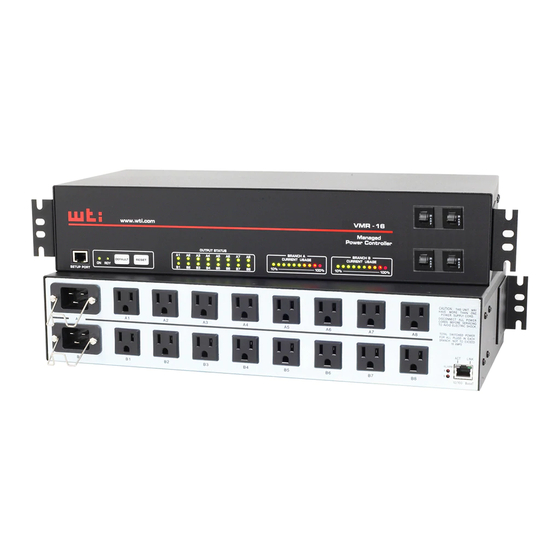
SETUP PORT 3 4 5 Figure 2.1: VMR Standard Series - Front Panel (Model VMR-16HD20-1 Shown) As shown in Figure 2.1, the VMR Series Front Panel includes the following components: SetUp Port: An RJ45 RS232 serial port (DCE configuration) used for connection to a local terminal or external modem, as described in Section 4.3. -
Page 13: Vmr Standard Series - Back Panel
LINK ALARM 10/100 BaseT Figure 2.2: VMR Standard Series - Back Panel (Model VMR-16HD20-1 Shown) 2.2. VMR Standard Series - Back Panel As shown in Figure 2.2, the VMR Series Back Panel includes the following components: Power Circuit A - Power Inlet: An IEC320-C20 AC inlet which supplies power to VMR control functions and Circuit “A”... -
Page 14: Vmr-Hd4D Series - Front Panel
Unit Description A1 A2 VMR-HD www.wti.com B1 B2 100% STATUS PLUG CURRENT USAGE 4 5 6 7 Figure 2.3: VMR-HD4D Series - Front Panel (Model VMR-HD4D32 Shown) 2.3. VMR-HD4D Series - Front Panel As shown in Figure 2.3, the VMR-HD4D Series Front Panel includes the following components: Branch B Circuit Breakers: Two circuit breakers, which protect Branch B. -
Page 15: Vmr-Hd4D Series - Back Panel
Unit Description LINK SETUP PORT 10/100 BaseT Figure 2.4: VMR-HD4D Series - Back Panel (Model VMR-HD4D32 Shown) 2.4. VMR-HD4D Series - Back Panel As shown in Figure 2.4, the VMR-HD4D Series Back Panel includes the following components: Power Circuit A - Power Inlet: Supplies power to VMR control functions and Circuit "A"... -
Page 16: Vmr-Hd4D-8 Series - Front Panel
Unit Description VMR-HD www.wti.com PLUG STATUS SYSTEM STATUS CURRENT USAGE CURRENT USAGE 100% 100% 2 3 4 5 6 7 Figure 2.5: VMR-HD4D-8 Series - Front Panel 2.5. VMR-HD4D-8 Series - Front Panel As shown in Figure 2.5, the VMR-HD4D-8 Series Front Panel includes the following... -
Page 17: Vmr-Hd4D-8 Series - Back Panel
Unit Description Figure 2.6: VMR-HD4D-8 Series - Back Panel 2.6. VMR-HD4D-8 Series - Back Panel As shown in Figure 2.6, the VMR-HD4D-8 Series Back Panel includes the following components: Power Inlets: Each inlet provides power to the two switched outlets on the corresponding branch. Notes: • VMR-HD4D30-8 units feature attached power supply cables with NEMA L6-30P Plugs. -
Page 18: Vmr-12B Series - Front Panel
LINK OUTPUT STATUS SYSTEM CURRENT USAGE CURRENT USAGE STATUS BRANCH A BRANCH B www.wti.com DEFAULT RESET 100% 100% B1 B2 B3 B4 B5 B6 10/100 BaseT SETUP PORT 1 2 3 4 5 6 7 Figure 2.7: VMR-12B Series - Front Panel (Model VMR-HD4D32-12B Shown) 2.7. -
Page 19: Vmr-12B Series - Back Panel
Unit Description Figure 2.8: VMR Series - Back Panel (Model VMR-HD4D32-12B Shown) 2.8. VMR-12B Series - Back Panel As shown in Figure 2.8, the VMR-12B Series Back Panel includes the following components: Power Circuit A - Power Inlet: An IEC320-C20 AC inlet which supplies power to VMR control functions and Circuit “A”... -
Page 20: Nps Series - Front Panel
Unit Description NPS-16 www.wti.com Network Power Switch A1 - A4 A5 - A8 OUTPUT STATUS DEFAULT RESET B1 - B4 B5 - B8 SETUP PORT 3 4 5 Figure 2.9: NPS Series - Front Panel (Model NPS-16HD20-1 Shown) 2.9. NPS Series - Front Panel As shown in Figure 2.9, the NPS Series Front Panel includes the following components:... -
Page 21: Nps Series - Back Panel
Unit Description LINK ALARM 10/100 BaseT Figure 2.10: NPS Series - Back Panel (Model NPS-16HD20-1 Shown) 2.10. NPS Series - Back Panel As shown in Figure 2.10, the NPS Series Back Panel includes the following components: Power Circuit A - Power Inlet: An IEC320-C20 AC inlet which supplies power to NPS control functions and the Circuit “A”... -
Page 22: Additional Button Functions
Unit Description 2.11. Additional Button Functions The Default and Reset buttons on the VMR or NPS front panel can be used to perform the functions described below: Notes: • All Front Panel Button functions can also be disabled via the System Parameters menu, as described in Section 6.2. • When the VMR or NPS is reset to factory defaults, all user-defined configuration parameters will be cleared, and the default “super” user account will also be restored. -
Page 23: Getting Started
VMR-HD4D-8 Series units include 10/100/1000Base-T Ethernet Ports, while all other VMR/NPS Models include 10/100Base-T Ethernet Ports. • Setup Port: Use the DX9F-WTI Adapter supplied with the unit to connect your PC COM port to the VMR or NPS SetUp Port. -
Page 24: Communicating With The Vmr Or Nps
Getting Started 3.2. Communicating with the VMR or NPS In order to ensure security, both Telnet and Web Browser Access are disabled when the VMR or NPS is shipped from the factory. To enable Telnet and/or Web Browser access, please refer to Section 6.8. When properly installed and configured, the VMR or NPS will allow command mode access via Telnet, Web Browser, SSH client, modem, or local PC. - Page 25 Getting Started Username / Password Prompt: A message will be displayed, which prompts you to enter your username and password. The default username is “super” (all lower case, no quotes), and the default password is also “super”. If a valid username and password are entered, the VMR or NPS will display either the Main Menu (Web Browser Interface) or the Port Status Screen (SSH, Telnet, or Modem.) Notes: • The default Username is "super".
-
Page 26: The Wmu Enterprise Management Solution
When installed at your network operation center or support facility, the WMU eliminates the need to individually access WTI units in order to perform firmware updates, control power switching functions, edit user accounts and perform other management and control functions. -
Page 27: Hardware Installation
4. Hardware Installation 4.1. Connecting the Power Supply Cables 4.1.1. Installing the Power Supply Cable Keepers The VMR/NPS includes cable keepers, which are designed to prevent the power supply cables from being accidentally disconnected from the unit. • VMR-8HD & NPS-8HD Series Units: The cable keepers for these units must be installed by the user. -
Page 28: Connect The Vmr Or Nps To Your Power Supply
4.3.1. Connecting a Local PC Use the DX9F-WTI Adapter supplied with the unit to connect your PC COM port to the VMR/NPS Setup Port. Make certain that the Serial Port Mode is set to “Normal” as described in Section 6.7. -
Page 29: Connecting The Network Cable
VMR/NPS Series units also include an Emergency Shut Off function, that can be used to immediately shut off all VMR/NPS power outlets in case of emergency. For more information regarding the Emergency Shut Off feature, please contact WTI Tech Support at service@wti.com. -
Page 30: Basic Operation
5. Basic Operation 5.1. Communicating with the VMR/NPS Unit In order to control and configure the VMR/NPS, you must first connect to the unit, and access command mode. Note that, the VMR/NPS offers two separate command interfaces; the Web Browser Interface and the Text Interface. In addition, the VMR/NPS also offers three different methods for accessing command mode;... - Page 31 Basic Operation To access command mode via the Text Interface, proceed as follows: Note: When communicating with the unit for the first time, you will not be able to contact the unit via Telnet, until you have accessed command mode, via Local PC or SSH Client, and used the Network Parameters Menu to enable Telnet as described in Section 6.8. Contact the VMR/NPS Unit: Via Local PC: Start your communications program and press [Enter]. Wait for the connect message, then proceed to Step 2. Via Network: The VMR/NPS includes a default IP address (192.168.168.168) and a default subnet mask (255.255.255.0.) This allows you to contact the unit from any network node on the same subnet, without first assigning an IP Address to the unit.
-
Page 32: The Web Browser Interface
When installed at your network operation center or support facility, the WMU eliminates the need to individually access WTI units in order to perform firmware updates, control power switching functions, edit user accounts and perform other management and control functions. -
Page 33: Controlling Power - Web Browser Interface
Basic Operation 5.2. Controlling Power - Web Browser Interface When using the Web Browser Interface, switching commands are invoked via the Plug Control Screen and Plug Group Control Screen. 5.2.1. The Plug Control Screen - Web Browser Interface The Plug Control Screen lists the On/Off status of the VMR/NPS Series unit's Switched Outlets and is used to control switching and rebooting of the outlets. -
Page 34: The Plug Group Control Screen - Web Browser Interface
Basic Operation 5.2.2. The Plug Group Control Screen - Web Browser Interface The Plug Group Control Screen is used to send switching and reboot commands to the user-defined Plug Groups. As described in Section 6.5, Plug Groups allow you to specify a group of outlets that are dedicated to a similar purpose or client, and then direct switching commands to the group, rather than switching one plug at a time. -
Page 35: Controlling Power - Text Interface
Basic Operation 5.3. Controlling Power - Text Interface When using the Text Interface, all power switching functions are performed by invoking simple, ASCII commands. ASCII commands are also used to display status screens and to log out of command mode. The Text Interface includes a Help Menu, which summarizes all available commands. -
Page 36: Switching And Reboot Commands - Text Interface
Basic Operation 5.3.2. Switching and Reboot Commands - Text Interface These commands can be used to switch or reboot the VMR/NPS Series unit’s switched plugs, and can also be used to set plugs to the user-defined Power-Up Default values. Plugs may be specified by name or number. Notes: • If an asterisk appears in the "Status" column for any given plug, this indicates that the plug is currently busy, processing a previously issued command. - Page 37 Basic Operation Switch Plug(s) Off: To power-off a plug or Plug Group, type /OFF n and press [Enter]. Where "n" is the number or name of the desired plug or Plug Group. Note that the “/OFF” command can also be entered as “/OF”. For example: /OFF 2 [Enter] or /OF ROUTER [Enter] Reboot Plug(s): To initiate a Boot cycle, type /BOOT n and press [Enter].
-
Page 38: Applying Commands To Several Plugs - Text Interface
Basic Operation 5.3.2.1. Applying Commands to Several Plugs - Text Interface As described below, switching and reboot commands can be applied to only one Switched AC Outlet, or to an assortment of outlets. Note: When switching and reboot operations are initiated, Boot/Sequence Delay times and user-defined Plug Priority values will be applied as described in Section 6.6. Switch Several Plugs: To apply a command to several plugs, enter the numbers or names for the plugs, separated by a "plus sign"... -
Page 39: The Automated Mode
Basic Operation 5.4. The Automated Mode The Automated Mode allows the VMR/NPS to execute switching and reboot commands, without displaying menus or generating response messages. Automated Mode is designed to allow the VMR/NPS to be controlled by a device which can generate commands to control power switching functions without human intervention. -
Page 40: Manual Operation
VMR/NPS Series units also include an Emergency Shut Off function, that can be used to immediately shut off all power outlets on an VMR/NPS Series unit in case of emergency. For more information regarding the Emergency Shut Off feature, please contact WTI Tech Support at service@wti.com. -
Page 41: Configuration Menus
6. Configuration Options This section describes the basic configuration procedure for VMR/NPS Series units. 6.1. Configuration Menus Although the Web Browser Interface and Text Interface provide two separate means for selecting parameters, both interfaces allow access to the same set of basic parameters, and parameters selected via one interface will also be applied to the other. -
Page 42: Defining System Parameters
Configuration Options 6.2. Defining System Parameters The System Parameters menus are used to define the Site ID Message, set the system clock and calendar, and configure the Invalid Access Lockout feature and Callback feature. To access the System Parameters menu via the Text Interface, type /F and press [Enter]. - Page 43 Configuration Options • Temperature Calibration: Used to calibrate the unit's internal temperature sensing abilities. To calibrate the temperature, place a thermometer inside your equipment rack, in a location that usually experiences the highest temperature. After a few minutes, take a reading from the thermometer, and then key the reading into the configuration menu.
- Page 44 Scripting Options: Provides access to parameters that are used to set up the VRM/NPS unit for running various scripts as described in Section 6.2.6. Notes: • The functions provided by the Scripting Options menu are intended for use in applications where scripts are employed to control VMR/NPS operation. Improper use of Scripting Options menu functions can cause the VMR/ NPS unit to become unresponsive. Prior to attempting to use the functions provided by the Scripting Options menu, please contact WTI Technical Support as described in Appendix C in this User's Guide. • In the Text Interface, the Scripting Options submenu is accessed via item 12. To access the Scripting Options parameters via the Web Browser Interface, place the cursor over the "General Parameters" link, wait for the flyout menu to appear, then click on the "Scripting Options" link. • Power Configuration: (VMR Only) In the Web Browser Interface, the Voltage Calibration parameter, Power Factor parameter and Power Efficiency parameter are defined via the System Parameters Menu.
-
Page 45: The Real Time Clock And Calendar
Configuration Options • Login Banner: Allows definition of a banner/message that will be displayed when a valid username and password are entered during log in. The Login Banner can be used to post legal warning regarding unauthorized access to the unit or to display other user-defined information or instructions. - Page 46 Configuration Options • Primary NTP Address: Defines the IP address or domain name (up to 64 characters long) for the primary NTP server. (Default = undefined.) Notes: • In order to use domain names for web addresses, DNS parameters must first be defined as described in Section 6.8.4. • The Web Browser Interface includes two separate fields that are allowed to define both an IPv4 protocol and IPv6 protocol format Primary NTP Address and Secondary NTP Address. • When the Primary NTP Address and Secondary NTP Address are defined via the Text Interface, the VMR/NPS will display a prompt that instructs the user to select IPv4 or IPv6 protocol. • The VMR/NPS allows parameters for both IPv4 and IPv6 protocols to be defined and saved. • Secondary NTP Address: Defines the IP address or domain name (up to 64 characters long) for the secondary, fallback NTP Server.
-
Page 47: The Invalid Access Lockout Feature
Configuration Options 6.2.2. The Invalid Access Lockout Feature When properly configured and enabled, the Invalid Access Lockout feature can watch all login attempts made via SSH connection, Telnet connection, web browser or the serial SetUp Port. If the counter for any of these exceeds the user-defined threshold for maximum invalid attempts, then the corresponding port or protocol will be automatically disabled for the length of time specified by the Lockout Duration parameter. - Page 48 Configuration Options • SSH Protection: Enables/Disables and configures the Invalid Access function for SSH connections. When this item is enabled and excessive Invalid Access Attempts via SSH are detected, then the VMR/NPS will lock out the offending MAC address for the user-defined SSH Lockout Duration Period or until the /UL command is issued.
- Page 49 Configuration Options • Web Protection: Enables/Disables and configures the Invalid Access function for Web connections. When this item is enabled and excessive Invalid Access Attempts via Web are detected, then the VMR/NPS will lock out the offending MAC address for the user-defined Web Lockout Duration Period or until the /UL command is issued.
-
Page 50: Syslog Messages
Configuration Options 6.2.3. Log Configuration This feature allows you to create records of command activity, alarm actions, temperature readings and current and power consumption for the VMR/NPS unit. The Log features are enabled and configured via the System Parameters Menus. • Audit Log: Creates a record of all power switching at the VMR/NPS unit, including reboots and switching caused by Load Shedding, Load Shedding Recovery, Ping No Answer Reboots and Scheduled Reboots. -
Page 51: The Temperature Log (Nps Units Only)
Configuration Options 6.2.3.2. The Temperature Log (NPS Units Only) The System Parameters menu allows you to either enable or disable the Temperature Log. When the Temperature Log is disabled, NPS units will not log temperature readings. In the default state, the Temperature Log is enabled. Note: The Temperature Log is not available on VMR units; instead, temperature values for the VMR unit can be displayed in the Text Interface via the Current Metering Log or in the Web Browser Interface via the Current Metering... -
Page 52: Current Metering Log Display Options (Vmr Only)
Configuration Options • Current Metering Log and Power Metering Log: (VMR Only) The Current Metering Log and Power Metering Log can be displayed or downloaded via either the Text Interface or Web Browser Interface. When the Current Metering Log is selected via the Text Interface, the VMR/NPS will also offer the option to erase Current Metering Log data. -
Page 53: Callback Security
Configuration Options 6.2.4. Callback Security The Callback function provides an additional layer of security when callers attempt to access command mode via modem. When this function is properly configured, modem users will not be granted immediate access to command mode upon entering a valid password;... -
Page 54: Power Source Configuration (Vmr Only)
Configuration Options • Callback Attempts: The number of times that the VMR/NPS will attempt to contact the Callback number. (Default = 3 attempts.) • Callback Delay: The amount of time that the VMR/NPS will wait between Callback attempts. (Default = 30 seconds.) Notes: • After configuring and enabling Callback Security, you must then define a callback phone number for each desired user account (as described in... -
Page 55: Scripting Options
Scripting Options The Scripting Options submenu provides access to parameters that are used to set up the VMR/NPS unit for running various scripts. Notes: • The functions provided by the Scripting Options menu are intended for use in applications where scripts are employed to control VMR/NPS operation. Improper use of Scripting Options menu functions can cause the VMR/ NPS unit to become unresponsive. Prior to attempting to use the functions provided by the Scripting Options menu, please contact WTI Technical Support as described in Appendix C in this User's Guide. • To access Scripting Options parameters via the Text Interface, first type /F and press [Enter] to display the System Parameters Menu, then key in the number for the Scripting Options item and press [Enter]. • To access the Scripting Options parameters via the Web Browser Interface, place the cursor over the "General Parameters" link, wait for the flyout menu to appear, then click on the "Scripting Options" link. The Scripting Options menu allows the following parameters to be defined: • Command Confirmation: Enables/Disables the Command Confirmation feature. - Page 56 • IPS Mode: This parameter sets up the VMR/NPS for use with command scripts that were written for WTI's IPS Series Remote Reboot Switches. When the IPS Mode is enabled, the "IPS" command prompt will be displayed in the Text Mode, User Accounts will not allow definition of a Username, and only the "password"...
-
Page 57: Automated Mode
Configuration Options • Reverse DNS: Determines the manner in which ARP requests are handled. When enabled (On,) the unit will check an external DNS in order to resolve domain names. When disabled (Off,) the unit will not check an external DNS when resolving domain names. - Page 58 Configuration Options To enable/disable the Automated Mode, go to the System Parameters menu (see Section 6.2,) and then set the “Automated Mode” option to “On”. When Automated Mode is enabled, VMR/NPS functions will change as follows: All Password Security Suppressed: When a user attempts to access command mode, the password prompt will not be displayed at either the Setup Port or Network Port.
-
Page 59: User Accounts
Configuration Options 6.3. User Accounts Each time you attempt to access command mode, you will be prompted to enter a username and password. The username/password entered at login determine which outlet(s) you will be allowed to control and what type of commands you will be allowed to invoke. -
Page 60: Granting Plug Access
Configuration Options 6.3.2. Granting Plug Access Each account can be granted access to a different selection of power outlets (plugs) and plug groups. When accounts are created, the Plug Access parameter and the Plug Group Access parameter in the Add User menu or Modify User menu are used to grant or deny access to each plug or plug group. -
Page 61: Managing User Accounts
Configuration Options 6.4. Managing User Accounts The User Directory function is employed to create new accounts, display parameters for existing accounts, modify accounts and delete accounts. Up to 128 different user accounts can be created. The "User Directory" function is only available when you have logged into command mode using an account that permits Administrator commands. - Page 62 Configuration Options • Authorization Keys: This item can be used to assign an SSH Authorization Key to the user account, view assigned authorization keys or delete assigned authorization keys. When a valid authorization key is assigned to a given user, that user will be able to access VMR/NPS command mode without entering a password.
- Page 63 Configuration Options • Service Access: Determines whether this account will be able to access command mode via Serial Port, Telnet/SSH or Web and whether or not the account will be allowed to initiate outbound connections. For example, if Telnet/SSH Access is disabled for this account, then this account will not be able to access command mode via Telnet or SSH.
-
Page 64: Modifying User Accounts
Configuration Options 6.4.3. Modifying User Accounts The "Edit User Directory" function allows you to edit existing accounts in order to change parameters, plug access rights or Administrator Command capability. Note that the Edit/Modify User function is only available when you have accessed command mode using a password that permits Administrator Level commands. -
Page 65: The Plug Group Directory
Configuration Options 6.5. The Plug Group Directory The Plug Group Directory allows you to designate "groups" of plugs that are dedicated to a similar function, and will most likely be switched or rebooted all at the same time or controlled by the same type of user account. For example, an individual equipment rack might include an assortment of devices that belong to different departments or clients. -
Page 66: Adding Plug Groups
Configuration Options 6.5.2. Adding Plug Groups The "Add Plug Group to Directory" option allows you to create new Plug Groups and assign plug access rights to each group. The Add Plug Group function is only available when you have accessed command mode using a password that permits Administrator Level commands. -
Page 67: Defining Plug Parameters
Configuration Options 6.6. Defining Plug Parameters The Plug Parameters Menu is used to define Plug Names, boot/sequence delay times and Power Up Default values for each VMR/NPS Switched AC Outlets. Note that this function is only available when you have accessed command mode using a password that permits Administrator Level commands. -
Page 68: The Boot Priority Parameter
Configuration Options 6.6.1. The Boot Priority Parameter Normally, when an "On" or "Reboot" command is invoked, the VMR/NPS will switch on its plugs in their default, numeric order. Although in many cases, the default, numeric order will work fine, there are other cases where an individual device (such as a router) must be switched on first, in order to support a second device that will be switched on later. -
Page 69: Example 2: Change Plug A5 To Priority 2
Configuration Options 6.6.1.2. Example 2: Change Plug A5 to Priority 2 In the second Example shown in Figure 6.2, we start out with Boot Priorities for the plugs set as they were at the end of Example 1; Plug A3 is first, Plug A1 is second, Plug A2 is third, Plug A4 is fourth, and Plug A6 is sixth. -
Page 70: Serial Port Configuration
• Handshake Mode: XON/XOFF, RTS/CTS (hardware), Both, or None. (Default = RTS/CTS). General Parameters: • Administrator Mode: In WTI console server products, this parameter is used to permit or deny port access to Administrator level accounts. In VMR/NPS products, Administrator access to the serial port cannot be disabled. - Page 71 Configuration Options • Accept Break: Determines whether the port will accept breaks received from the attached device. When enabled, breaks received at the port will be passed to any port that this port is connected to. When disabled, breaks will be refused at this port.
- Page 72 Configuration Options Reset/No Dialtone Scaler: Determines the number of Periodic Modem Reset sequences that must occur in order to initiate a No Dialtone Check. If this parameter is set to "0," then the No Dialtone Alarm will not function. When both this parameter and the Reset/No Dialtone Interval are set to a value from 1 to 99 and the No Dialtone Alarm is enabled, the VMR/NPS will initiate a No Dialtone Check after a time period equal to the defined Reset/No Dialtone Interval value multiplied by the Reset/No Dialtone Scaler value.
- Page 73 Configuration Options PPP Phone Number: The phone number for the line that will be used for PPP communication. (Default = undefined) User Name: The user name for the ISP account that will be used for PPP communication. (Default = undefined) Password: The password for the ISP count that will be used for PPP ...
-
Page 74: Network Configuration
Configuration Options 6.8. Network Configuration The Network Parameters Menus are used to select parameters and options for the Network Port and also allow you to implement IP Security features, which can restrict access based on the user’s IP Address. Although the Web Browser Interface and Text Interface allow definition of essentially the same parameters, parameters are arranged differently in the two interfaces. - Page 75 Configuration Options The Network Configuration Menus: The Network Configuration menus allow you to define both IPv4 parameters and IPv6 parameters for the Ethernet Port. Although there are slight differences in the manner in which the Web Interface and Text Interface Network are organized, both interfaces provide access to essentially the same set of network parameters (with a few noted exceptions.) Since the network configuration menus must allow definition of network parameters for...
-
Page 76: Network Port Parameters
Configuration Options 6.8.1. Network Port Parameters Note: The IP Address, Subnet Mask, Subnet Prefix, Gateway Address and DHCP status cannot be changed via the Web Browser Interface. In order to change these parameters, you must access the VMR/NPS via the Text Interface. • IP Address: (Defaults: IPv4 = 192.168.168.168; IPv6 = undefined) • Subnet Mask: (IPv4 Only; Default = 255.255.255.0) • Subnet Prefix: (IPv6 Only; Default = undefined) • Gateway Address: (Default = undefined.) • DHCP: Enables/Disables Dynamic Host Configuration Protocol. When this option is "On", the VMR/NPS will perform a DHCP request. - Page 77 Configuration Options • Sequence Disconnect: Enables/Disables and configures the Resident Disconnect command. Offers the option to either disable the Sequence Disconnect, or select a one character, or three character command format. (Default = One Character). Notes: • The One Character Disconnect is intended for situations where the destination port should not receive the disconnect command. When the Three Character format is selected, the disconnect sequence will pass through to the destination port prior to breaking the connection. • When Three Character format is selected, the Resident Disconnect uses the format "[Enter]LLL[Enter]", where L is the selected Logoff Character.
- Page 78 Configuration Options • SSH Access: Enables/disables SSH communication. (Default = On.) Note: In the Text Interface, the SSH Access submenu also allows you to select the SSH Port and other parameters. In the Web Browser Interface, some of these parameters are set via the Shared Network Parameters menu. • SSH Port: Selects the TCP/IP port number that will be used for SSH connections. Note: In the Text Interface, this option is defined via the SSH Access submenu. (Default = 22.) • SSH Security Level: (Text Interface Only) Sets the SSH Security Level to either Normal or High.
- Page 79 Configuration Options • HTTP Port: Selects the TCP/IP port number that will be used for Web Access. (Default = 80.) Notes: • In the Text Interface, the HTTP Port parameter is accessed via the Web Access submenu. • In the Web Browser Interface, the HTTP Port parameter is accessed via the Web Access menu. • HTTPS Access: Enables/disables HTTPS communication. For instructions on setting up SSL encryption, please refer to Section 14. (Default = On.) Notes: • In the Text Interface, the HTTPS Access parameter is accessed via a Web Access submenu.
- Page 80 Configuration Options • Trace Method: Enables/disables the Web Trace Method. (Default = Off) Notes: • In the Text Interface, the Trace Method parameter is accessed via the Web Access submenu. • In the Web Browser Interface, the Trace Method parameter is accessed via the Web Access menu. • SYSLOG Addresses: Defines the IP addresses for the Syslog Daemon(s) that will receive log records generated by the VMR/NPS. Allows definition of IP addresses for both a primary Syslog Daemon and an optional secondary Syslog Daemon.
- Page 81 Configuration Options • Multiple Logins: (Text Interface Only) If the VMR/NPS is installed in an environment that does not include communication via an open network (local communication only), then the Multiple Logins parameter can be used to determine whether or not multiple users will be able to communicate with the unit at the same time.
-
Page 82: Ip Tables
The DNS Parameters menu is used to select IPv4 or IPv6 format IP addresses for Domain Name Servers. When web and network addresses are entered, the Domain Name Server interprets domain names (e.g., www.wti.com), and translates them into IP addresses. Note that if you don't define at least one DNS server, then IP addresses must be used, rather than domain names. -
Page 83: Snmp Traps
Configuration Options 6.8.4.2. DDNS Parameters The DDNS Parameters menu is used to select parameters and define hosts for Dynamic DNS services. The DDNS Parameters menu includes the following parameters:: • Services: This item is used to set the service type to either Dyn or None. (Default = None) • Host Name: The IP Address for the DDNS Service. - Page 84 Configuration Options • Authentication / Privacy: Configures the Authentication and Privacy features for SNMPv3 communication. The Authentication / Privacy parameter offers two options, which function as follows: Auth/noPriv: An SNMPv3 username and password will be required at log in, but encryption will not be used. (Default Setting.) Auth/Priv: An SNMPv3 username and password will be required at log in, and all messages will be sent using encryption.
-
Page 85: Snmp Trap Parameters
Configuration Options 6.8.6. SNMP Trap Parameters These menus are used to select parameters that will be used when SNMP traps are sent. For more information on SNMP Traps, please refer to Section 12. In the Text Interface, the SNMP Trap Parameters menu is accessed via the Network Configuration menu. -
Page 86: Ldap Parameters
Configuration Options 6.8.7. LDAP Parameters The VMR/NPS supports LDAP (Lightweight Directory Access Protocol,) which allows authentication via the "Active Directory" network Directory Service. When LDAP is enabled and properly configured, command access rights can be granted to new users without the need to define individual new accounts at each VMR/NPS unit, and existing users can also be removed without the need to delete the account from each VMR/NPS unit. - Page 87 • LDAP Group Setup: Provides access to a submenu, which is used to define LDAP Groups as described in the Sections 6.8.7.1 through 6.8.7.4. • Debug: This option is used to assist WTI Technical Support personnel with the diagnosis of LDAP issues. (Default = Off) • Ping Test: Allows you to ping IP addresses or domain names that have been...
-
Page 88: Adding Ldap Groups
Configuration Options 6.8.7.1. Adding LDAP Groups Once you have defined users and passwords via your LDAP server, and assigned users to LDAP Groups, you must then grant command and port access rights to each LDAP Group at each individual VMR/NPS unit. In order to Add an LDAP Group, you must access the VMR/NPS command mode using a password that permits Administrator Level commands. -
Page 89: Modifying Ldap Groups
Configuration Options 6.8.7.3. Modifying LDAP Groups If you want to modify an existing LDAP Group in order to change parameters or plug access rights, the "Modify LDAP Group" function can be used to reconfigure group parameters. To Modify an existing LDAP Group, you must access the VMR/ NPS command mode using a password that permits access to Administrator Level commands. -
Page 90: Tacacs Parameters
Configuration Options 6.8.8. TACACS Parameters The TACACS Configuration Menus offer the following options: • Enable: Enables/disables the TACACS feature at the Network Port. (Default = Off) • Primary Address: Defines the IP address or domain name (up to 64 characters) for your primary TACACS server. (Default = undefined) • Secondary Address: Defines the IP address or domain name (up to 64 characters) for your secondary, fallback TACACS server (if present.) (Default = undefined) • Secret Word: Defines the shared TACACS Secret Word for both TACACS servers. - Page 91 Configuration Options Port Access: Determines the default Port Access setting for new TACACS users. The Port Access setting determines whether or not the account will be allowed to connect to the serial Setup Port. (Defaults; Administrator and SuperUser = Always Enabled, User = Disabled) Note: ViewOnly level accounts cannot be granted access to the Setup Port.
- Page 92 Configuration Options Current/Power Metering: (VMR Only) Selects the default enable/disable status for the Current/Power Metering setting. When Current/Power Metering is disabled, an account will not be able to view current or power readings or display current or power history. Note that in order for accounts to be able to display these logs, Current and Power Metering must be enabled via the Systems Parameters menu as described in Section 6.2.
-
Page 93: Radius Parameters
Configuration Options 6.8.9. RADIUS Parameters Notes: • In the Text Interface, the IPv4 and IPv6 RADIUS Parameters menus are accessed via the Network Configuration menu as described in Section 6.8. • In the Web Browser Interface, both IPv4 and IPv6 parameters are defined via a single RADIUS Parameters menu, which is accessed via the flyout menus under the Network Configuration link. The RADIUS Configuration Menus offer the following options: • Enable: Enables/Disables the RADIUS feature at the Network Port. (Default = Off) • Primary Host: Defines the IP address or domain name for your primary RADIUS server. -
Page 94: Dictionary Support For Radius
The RADIUS dictionary file, "dictionary.wti" is included on the CDROM along with this user's guide. To install the dictionary file on your RADIUS server, please refer to the documentation provided with your server;... - Page 95 Configuration Options • WTI-Plug-Access - Determines which plug(s) the user will be allowed to access. This command provides an argument that consists of a character string, with one character for each the VMR/NPS's switched outlets. The following options are available:...
-
Page 96: Email Messaging Parameters
Configuration Options 6.8.10. Email Messaging Parameters The Email Messaging menu is used to define parameters for email messages that the VMR/NPS can send to notify you when an alarm is triggered. To define email message parameters, you must access the VMR/NPS Command Mode using a password that permits access to Administrator Level commands. -
Page 97: Save User Selected Parameters
Configuration Options 6.9. Save User Selected Parameters It is strongly recommended to save all user-defined parameters to a file as described in Section 15. This will allow quick recovery in the event of accidental deletion or reconfiguration of port parameters. When changing configuration parameters via the Text Interface, make certain that the VMR/NPS has saved the newly defined parameters before exiting from command mode. -
Page 98: Reboot Options
7. Reboot Options In addition to performing reboot cycles in response to commands, the VMR/NPS can also be configured to automatically reboot outlets when an attached device does not respond to a Ping command (Ping-No-Answer Reboot) or according to a user defined schedule (Scheduled Reboot.) • Ping-No-Answer Reboot: When the Ping-No-Answer feature is enabled, the VMR/ NPS will Ping a user selected IP address at regular intervals. -
Page 99: Ping-No-Answer Reboot
Reboot Options 7.1. Ping-No-Answer Reboot A Ping-No-Answer Reboot can be used to reboot one or more outlets when an attached device does not respond to a Ping Command. In addition, the Ping-No-Answer Reboot feature can also be configured to send an email, Syslog Message or SNMP Trap to notify you whenever a Ping-No-Answer Reboot occurs. - Page 100 Reboot Options • Ping Delay After PNA Action: Determines how long the VMR/NPS will wait to send additional Ping commands, after a Ping-No-Answer Reboot has been initiated. Typically, this option is used to allow time for a device to fully "wake up" after a Ping-No-Answer Reboot before attempting to Ping the device again.
-
Page 101: Viewing Ping-No-Answer Reboot Profiles
Reboot Options • Ping Test: Sends a test Ping command to the IP Address defined for this Ping-No- Answer Reboot. Notes: • In order for the Ping Test function to work properly, your network and/or firewall as well as the device at the target IP address must be configured to allow ping commands. • After you have finished defining or editing Ping-No-Answer Reboot parameters, make certain to save the changes before proceeding. In the Web Browser Interface, click on the "Add Ping No Answer" button to save parameters; in the Text Interface, press the [Esc] key several times until the MPC displays the "Saving Configuration" message and the cursor returns to the command prompt. 7.1.2. Viewing Ping-No-Answer Reboot Profiles After you have defined one or more Ping-No-Answer Reboot profiles, you can review the parameters selected for each profile using the View Ping-No-Answer feature. -
Page 102: Scheduled Reboot
Reboot Options 7.2. Scheduled Reboot The Scheduled Reboot feature can be used to reboot one or more outlets according to a user-defined schedule, or to automatically turn outlets Off and then On according to a user defined schedule. In order to configure a Scheduled Reboot, you must access command mode using a password that permits access to Administrator level commands. -
Page 103: Viewing Scheduled Reboot Actions
Reboot Options • Plug Access: Determines which outlet(s) this Scheduled Reboot action will be applied to. In the Text Interface, outlets are selected by typing 9, pressing [Enter] and then following the instructions in the resulting submenu. In the Web Browser Interface, outlets are designated by clicking on the "plus"... -
Page 104: Alarm Configuration
8. Alarm Configuration When properly configured, VMR and NPS units can monitor rack temperature, ping command response and other factors at network installation sites. In addition to the monitoring abilities listed above, VMR series units can also measure and record current, power and voltage conditions. -
Page 105: The Over Current Alarms (Vmr Only)
Alarm Configuration 8.1. The Over Current Alarms (VMR Only) The Over Current Alarms are designed to inform you when current consumption reaches or exceeds user-defined levels. Depending on the specific VMR model, VMR units can have up to four Over Current Alarms (two sets of two alarms): • The Over Current Line (Initial) Alarm • The Over Current Line (Critical) Alarm • The Over Current Branch (Initial) Alarm... - Page 106 Alarm Configuration To configure the Over Current Alarms, access the VMR command mode using a password that permits Administrator Level commands, and then use the Alarm Configuration menu to select the desired alarm feature. Note that the configuration menus for both Over Current Alarms offer essentially the same set of parameters, but the parameters defined for each alarm are separate.
-
Page 107: Over Current Alarms - Load Shedding And Auto Recovery
Alarm Configuration • Subject: This parameter is used to define the text that will appear in the "Subject" field for all email notification messages generated by the alarm. (Defaults = "Alarm: Over Current (Initial)" or "Alarm: Over Current (Critical)") • Load Shedding: Provides access to a submenu which is used to configure and enable the Load Shedding feature for the Over Current Alarm. - Page 108 Alarm Configuration • Line Input A: Defines the Load Shedding actions that will be executed when an Over Current Branch Alarm is triggered at Line Input "A". • Line Input B: Defines the Load Shedding actions that will be executed when an Over Current Branch Alarm is triggered at Line Input "B". • Fuse A1-A4: Defines the Load Shedding actions that will be executed when an Over Current Branch Alarm is triggered at Fuses A1 through A4.
-
Page 109: The Over Temperature Alarms
Alarm Configuration 8.2. The Over Temperature Alarms The Over Temperature Alarms are designed to inform you when the temperature level inside your equipment rack reaches or exceeds certain user-defined levels. There are two separate Over Temperature Alarms; the Initial Threshold alarm and the Critical Threshold Alarm. - Page 110 Alarm Configuration • Alarm Set Threshold: The trigger level for this alarm. When temperature exceeds the Alarm Set Threshold, the VMR/NPS can send an alarm (if enabled) and/or begin Load Shedding (if enabled.) For more information on Load Shedding for the Over Temperature Alarm, please refer to Section 8.2.1.
-
Page 111: Over Temperature Alarms - Load Shedding And Auto Recovery
Alarm Configuration 8.2.1. Over Temperature Alarms - Load Shedding and Auto Recovery For Over Temperature Alarms, the Load Shedding feature is used to switch specific, user-defined plugs On or Off whenever temperature exceeds the Alarm Set Threshold value. This allows the VMR/NPS to automatically shut off non-essential devices in order to reduce the temperature generated within the rack, or automatically switch On devices such as fans or cooling systems in order to dissipate heat. -
Page 112: The Circuit Breaker Open Alarm
Alarm Configuration 8.3. The Circuit Breaker Open Alarm The Circuit Breaker Alarm is intended to provide notification in the event that one of the VMR/NPS's circuit breakers is opened. When a circuit breaker is open, the VMR/NPS can provide prompt notification via Email, Syslog Message or SNMP Trap. Notes: • The Circuit Breaker Open Alarm is not applicable to some VMR models. - Page 113 Alarm Configuration • Address 1, 2, and 3: These parameters are used to select which of the three email addresses defined via the "Email Messages" menu (see Section 6.8.10) will receive the email alarm notification messages generated by this alarm. The Address parameters can be used to select one, or any combination of the addresses defined via the Email Messages menu.
-
Page 114: The Lost Voltage (Line In) Alarm
Alarm Configuration 8.4. The Lost Voltage (Line In) Alarm The Lost Voltage (Line In) Alarm can provide notification after the power supply to the VMR/NPS unit has been interrupted. Notes: • The Lost Voltage (Line In) alarm is only available on VMR/NPS units that include two input power lines. • The Lost Voltage (Line In) alarm will provide notification when one of the available power supplies is lost or disconnected. This alarm will not function if all input power to the VMR/NPS unit is lost. To provide notification when all input power is lost and restored, please use the Power Cycle Alarm as described in Section 8.7. • In order for the VMR/NPS to provide alarm notification via Email, communication parameters must first be defined as described in Section 6.8.10. -
Page 115: The Ping-No-Answer Alarm
Alarm Configuration • Email Message: Enables/Disables email notification for this alarm. (Default = On.) • Address 1, 2, and 3: These parameters are used to select which of the three email addresses defined via the "Email Messages" menu (see Section 5.8.10) will receive the email alarm notification messages generated by this alarm. The Address parameters can be used to select one, or any combination of the addresses defined via the Email Messages menu. - Page 116 Alarm Configuration To configure the Ping-No-Answer Alarm, you must access the VMR/NPS command mode using a password that permits Administrator Level commands. The Ping-No- Answer alarm configuration menu offers the following parameters: • Trigger Enable: Enables/Disables the trigger for this alarm. When disabled, this alarm will be suppressed.
-
Page 117: The Serial Port Invalid Access Lockout Alarm
Alarm Configuration 8.6. The Serial Port Invalid Access Lockout Alarm The Serial Port Invalid Access Lockout Alarm can provide notification when the VMR/ NPS has locked the serial SetUp Port due to repeated, invalid attempts to access command mode. Normally, the Invalid Access Lockout feature (discussed in Section 6.2.2) can lock the serial SetUp Port whenever the unit detects that a user- defined threshold for invalid access attempts at the SetUp Port is exceeded. - Page 118 Alarm Configuration • Resend Delay: Determines how long the VMR/NPS will wait to resend an email message generated by this alarm, when the initial attempt to send the notification was unsuccessful. (Default = 60 Minutes.) • Notify Upon Clear: When this item is enabled, the VMR/NPS will send additional notification when the situation that caused the alarm has been corrected.
-
Page 119: The Power Cycle Alarm
Alarm Configuration 8.7. The Power Cycle Alarm The Power Cycle Alarm can provide notification when all input power to the VMR/NPS unit is lost and then restored. When the power supply is lost and then restored, the VMR/NPS can provide notification via Email, Syslog Message or SNMP Trap. Notes: • This alarm will not function when only one power input line is disconnected. -
Page 120: The Plug Current Alarm (Vmr Only)
Alarm Configuration 8.8. The Plug Current Alarm (VMR Only) The Plug Current Alarm allows you to monitor current consumption at each of the VMR's switched outlets and generate an alarm when current exceeds a user-defined "High" threshold or falls below a user-defined "Low" threshold. The Plug Current Alarm can also be applied to user-defined Plug Groups in order to generate an alarm when total current consumption for the given Plug Group rises too high or falls too low. - Page 121 Alarm Configuration • Plug Thresholds: Defines current consumption level(s) that will trigger alarm(s) at each switched outlet. The Plug Thresholds can be configured to trigger an alarm when current consumption rises above a user-defined "High" value and/or when current consumption falls below a user-defined "Low" value. This allows you to define a "normal"...
- Page 122 Alarm Configuration • Email Message: Enables/Disables email notification for this alarm. (Default = On.) • Address 1, 2, and 3: These parameters are used to select which of the three email addresses defined via the "Email Messages" menu (see Section 6.8.10) will receive the email alarm notification messages generated by this alarm. The Address parameters can be used to select one, or any combination of the addresses defined via the Email Messages menu.
-
Page 123: The Emergency Shutoff Alarm
Alarm Configuration 8.9. The Emergency Shutoff Alarm The Emergency Shutoff Alarm can provide notification when the VMR/NPS Emergency Shutoff feature is triggered. Notes: • In order for the VMR/NPS to provide alarm notification via Email, communication parameters must first be defined as described in Section 6.8.10. • In order for the VMR/NPS to provide alarm notification via Syslog Message, Syslog parameters must first be defined and Syslog Messages must be enabled as described in Section 6.8 and Section 11. • In order for the VMR/NPS to provide alarm notification via SNMP Trap, SNMP parameters must first be defined, and SNMP Traps must be enabled as described in Section 6.8.6 and Section 12. To configure the Emergency Shutoff Alarm, you must access the VMR/NPS command mode using a password that permits Administrator Level commands. - Page 124 Alarm Configuration • Email Message: Enables/Disables email notification for this alarm. (Default = On) • Address 1, 2, and 3: These parameters are used to select which of the three email addresses defined via the "Email Messages" menu (see Section 6.8.10) will receive the email alarm notification messages generated by this alarm. The Address parameters can be used to select one, or any combination of the addresses defined via the Email Messages menu.
-
Page 125: The No Dialtone Alarm
Alarm Configuration 8.10. The No Dialtone Alarm The No Dialtone Alarm enables the VMR/NPS to monitor a telephone line connected to an external modem installed at the VMR/NPS Setup Port, and then provide notification if the VMR/NPS detects that the phone line is dead or no dialtone is present. If the No Dialtone Alarm is enabled and the VMR/NPS determines that there is no dialtone signal, the No Dialtone Alarm can provide notification via email using a network connection. - Page 126 Alarm Configuration • Notify Upon Clear: When this item is enabled, the VMR/NPS will send additional notification when the situation that caused the alarm has been corrected. For example, when Notify Upon Clear is enabled, the VMR/NPS will send initial notification when it detects that the dialtone for the external modem has been lost, and then send a second notification when it determines that the dialtone has been restored.
-
Page 127: The Status Screens
[Enter]. To display the Product Status Screen via the Web Browser Interface, click on the "Product Status" link. Note: The Information provided by the Product Status Screen is intended mainly to assist WTI support personnel with the diagnosis of user equipment problems. 9.2. The Network Status Screen The Network Status screen shows activity at the VMR/NPS's 16 virtual network ports. To view the Network Status Screen, you must access command mode using a password that permits access to Administrator Level commands. -
Page 128: The Plug Status Screen
The Status Screens 9.3. The Plug Status Screen The Plug Status screen shows the On/Off status of the VMR/NPS's switched outlets. Note: • When the Plug Status Screen is viewed by an "Administrator" or "SuperUser" level account, all VMR/NPS plugs are listed. When the Plug Status Screen is viewed by a "User" or "ViewOnly" level account, the screen will list only the outlets that are allowed by that account. • Section 6.6 describes the procedure for configuring the plug parameters that are listed in the Plug Status Screen. To display the Plug Status Screen via the Text Interface, type /S and press [Enter]. To display the Plug Status Screen via the Web Browser Interface, click on the "Plug Status"... -
Page 129: The Plug Group Status Screen
The Status Screens 9.4. The Plug Group Status Screen The Plug Group Status screen shows the configuration details and On/Off status for the VMR/NPS's user-defined Plug Groups. Notes: • Current and Power Monitoring features are not available on NPS units. • When the Plug Group Status Screen is viewed by an "Administrator" or "SuperUser" level account, all VMR/NPS plugs and plug groups are listed. When the Plug Status Screen is viewed by a "User" or "ViewOnly" level account, the screen will list only the plug groups that are allowed by that account. • The procedure for defining parameters for individual plugs is described in Section 6.6. The procedure for defining Plug Groups is described in Section 6.5. • In order to display the Plug Group Status screen, you must first define at least one Plug Group as described in Section 6.5. -
Page 130: The Current Metering Status Screen
The Status Screens 9.5. The Current Metering Status Screen The Current Metering Status screen is primarily intended to be used to display up-to- date readings for Amps, Watts, Voltage and temperature for VMR Series unit. In NPS Series units, the Current Metering Status Screen will only include temperature and voltage information. -
Page 131: The Current History Screen (Vmr Only)
The Status Screens 9.6. The Current History Screen (VMR Only) The Current History Screen displays current, voltage and temperature readings as a function of time. In the Web Browser Interface, the Current History can be displayed as a graph or downloaded in ASCII, CSV or XML format. In the Text Interface, the Current History can be displayed as straight ASCII data, or can be downloaded in CSV or XML format. -
Page 132: The Power Range Status Screen (Vmr Only)
The Status Screens 9.7. The Power Range Status Screen (VMR Only) The Power Range Status Screen can be used to display power consumption readings over a user-selected period of time, for the VMR unit as well as any optional remote VMR units that may be connected. -
Page 133: The Power History Screen (Vmr Only)
The Status Screens 9.8. The Power History Screen (VMR Only) The Power History Screen shows power consumption versus time. To view the Power History Screen, access the VMR command mode using an account that permits access to Administrator or SuperUser level commands, and then proceed as follows: Note: The Power History Screen is not available on NPS units. -
Page 134: The Port Diagnostics Screen
The Status Screens 9.9. The Port Diagnostics Screen The Port Diagnostics Screen provides more detailed information about the VMR/NPS's Serial Port. To display the Port Diagnostics Screen, access the Text Interface command mode and type /SD [Enter]. Note: The Port Diagnostics Screen is only available via the Text Interface. 9.10. Alias Status Screen The Alias Status Screen lists user defined IP alias for the VMR/NPS's Serial Port. -
Page 135: The Event Logs
The Status Screens 9.13. The Event Logs The Event Logs can be used to review recent user activity, alarm events and temperature trends that have been recorded by the VMR/NPS unit. In order to view, download or erase the event logs, you must access command mode using a password that permits Administrator or SuperUser level commands. -
Page 136: Ssh Encryption
10. SSH Encryption In addition to standard Telnet protocol, the VMR/NPS also supports SSH connections, which provide secure, encrypted access via network. In order to communicate with the VMR/NPS using SSH protocol, your network node must include an appropriate SSH client. Note that when the /K (Send SSH Key) command is invoked, the VMR/NPS can also provide you with a public SSH key, which can be used to streamline connection to the VMR/NPS when using SSH protocol. - Page 137 11. Syslog Messages The Syslog feature can create log records of each Alarm Event. As these event records are created, they are sent to a Syslog Daemon, located at an IP address defined via the Network Parameters menu. 11.1. Configuration If you wish to employ this feature, you must set the real-time clock and calendar via the System Parameters Menu, and define the IP address for the Syslog Daemon via the Network Port Configuration menu.
- Page 138 12. SNMP Traps The SNMP Trap function allows the VMR/NPS to send Alarm Notification messages to two different SNMP managers, each time one of the Alarms discussed in Section 8 is triggered. Note: • The SNMP feature cannot be configured via the SNMP Manager. • SNMP reading ability is limited to the System Group. • The SNMP feature includes the ability to be polled by an SNMP Manager. • Once SNMP Trap Parameters have been defined, SNMP Traps will be sent each time an Alarm is triggered. For more information on Alarm Configuration, please refer to Section 8.
-
Page 139: Operation Via Snmp
The VMR/NPS’s SNMP Agent supports various configuration, control, status and event notification capabilities. Managed objects are described in WTI-MPC-VMR-MIB.txt, which can be found in the user's guide archive on the WTI web site at: http://www.wti.com/manuals.htm The WTI-MPC-VMR-MIB.txt document can be compiled for use with your SNMP client. -
Page 140: Configuration Via Snmp
Operation via SNMP 13.3. Configuration via SNMP VMR/NPS User accounts can be viewed, created, modified, and deleted via SNMP . User accounts are arranged in a table of 128 rows, and indexed 1-128. User account parameters, as seen through the SNMP , are summarized below. Note: Current and Power Monitoring features are not available on NPS units. -
Page 141: Viewing Users
Operation via SNMP 13.3.1. Viewing Users To view users, issue a GET request on any of the user parameters for the index corresponding to the desired user. 13.3.2. Adding Users For an empty index, issue a SET request on the desired parameters. Minimum requirement is a username and password to create a user, all other parameters will be set to defaults if not specified. -
Page 142: Plug Control Via Snmp
Operation via SNMP 13.4. Plug Control via SNMP 13.4.1. Plug Status/Control ON, OFF, BOOT, and DEFAULT commands can be issued for plugs via SNMP . Plugs are arranged in a table of N rows, where N is the number of plugs in the system. Plug parameters are described below. -
Page 143: Plug Group Status/Control
Operation via SNMP 13.4.2. Plug Group Status/Control ON, OFF, BOOT, and DEFAULT commands can be issued for plug groups via SNMP . Plug groups are arranged in a table of 54 rows, one row for each plug group in the system. -
Page 144: Viewing Vmr/Nps Status Via Snmp
Operation via SNMP 13.5. Viewing VMR/NPS Status via SNMP Status of various components of the VMR/NPS can be retrieved via SNMP . 13.5.1. System Status - Ethernet Port Mac Addresses The Mac Address for the Ethernet Port can be displayed using the command below: • environmentUnitTable::environmentMacEth0 The Mac Address for Ethernet Port 0. -
Page 145: Alarm Status
• alarmTables::alarmNoDialtone - Displays the status of the No Dialtone Alarm. • alarmTables::alarmEmergencyShutoff - Displays the status of the Emergency Shut Off feature. For more information regarding the Emergency Shut Off feature, please contact WTI Tech Support at service@wti.com. 13-7... -
Page 146: Sending Traps Via Snmp
Operation via SNMP 13.6. Sending Traps via SNMP Traps that report various unit conditions can be sent to an SNMP Management Station from the VMR/NPS. The following traps are currently supported. • WarmStart Trap – Trap indicating a warm start • ColdStart Trap –... - Page 147 • emergencyShutoffSetTrap - Indicates that an emergency shut off has been implemented. For more information regarding the Emergency Shut Off feature, please contact WTI Tech Support at service@wti.com. • emergencyShutoffClearTrap - Indicates that an emergency shut off has been cleared. For more information regarding the Emergency Shut Off feature, please contact WTI Tech Support at service@wti.com.
-
Page 148: Creating Web Certificates
14. Creating Web Certificates There are two different types of HTTPS security certificates: "Self Signed" certificates and "Signed" certificates. Note: SSL/TLS parameters cannot be defined via the Web Browser Interface. In order to set up SSL/TLS encryption, you must contact the VMR/NPS via the Text Interface. Self Signed certificates can be created by the VMR/NPS, without the need to go to an outside service. The principal disadvantage of Self Signed certificates, is that when you access the VMR/NPS command mode via the Web Browser Interface, the browser will display a message which warns that the connection might be unsafe. -
Page 149: Creating A Self Signed Certificate
Creating Web Certificates 14.1. Creating a Self Signed Certificate To create a Self Signed certificate, access the Text interface using a password that permits access to Administrator level commands and then proceed as follows: Type /N and press [Enter] to display the Eth0/IPv4 (Shared) Network Parameters menu. -
Page 150: Creating A Signed Certificate
Creating Web Certificates After you have defined parameters 5 through 11, type 12 and press [Enter] to access the CSR Commands menu. From the CSR Commands Menu, type 1 and press [Enter] to generate a Certificate Signing Request. This will overwrite any existing certificate, and create a new Self Signed certificate. - Page 151 After the configuration has been saved, test the signed certificate by accessing the VMR/NPS via the Web Browser Interface, using an HTTPS connection. For example, if the common name has been defined as "service.wti.com", then you would enter "https://service.wti.com" in your web browser's address field.
-
Page 152: Downloading The Server Private Key
Creating Web Certificates 14.3. Downloading the Server Private Key When configuring the VMR/NPS's SSL/TLS encryption feature (or setting up other security/authentication features), it is recommended to download and save the Server Private Key. To download the Server Private Key, access the Text interface using a password that permits access to Administrator level commands and then proceed as follows: Type /N and press [Enter] to display the Eth0/IPv4 (Shared) Network... -
Page 153: Saving And Restoring Configuration Parameters
15. Saving and Restoring Configuration Parameters Once the VMR/NPS is properly configured, parameters can be downloaded and saved as an ASCII text file. Later, if the configuration is accidentally altered, the saved parameters can be uploaded to automatically reconfigure the unit without the need to manually assign each parameter. -
Page 154: Downloading & Saving Parameters Via Web Browser Interface
Saving and Restoring Configuration Parameters 15.1.2. Downloading & Saving Parameters via Web Browser Interface The Web Browser Interface also includes a download function that can be used to save VMR/NPS parameters to an XML format file on your PC or laptop. To save parameters via the Web Browser Interface, proceed as follows: Notes: • Although VMR/NPS parameters can be saved to a file via either the Text... -
Page 155: Restoring Previously Saved Parameters
Saving and Restoring Configuration Parameters 15.3. Restoring Previously Saved Parameters If you make a mistake while configuring the VMR/NPS unit, and wish to return to the previously saved parameters, the Text Interface's "Reboot System" command (/I) offers the option to reinitialize the VMR/NPS unit using previously backed up parameters. This allows you to reset the unit to previously saved parameters, even after you have changed parameters and saved them. -
Page 156: Upgrading Vmr/Nps Firmware
WTI units from a single interface. For a description of the process for managing firmware updates via the WMU, please refer to the WMU user's guide, which can be downloaded from the WTI User's Guide Archive at: http://www.wti.com/t-product-manuals.aspx Note that in order to use the WMU software, the firmware version for the VMR/NPS must be at least v1.48 or higher. - Page 157 Start FTP/SFTP Servers for Slip Stream Upgrade: This option will upgrade only the WTI Management Utility, without updating the VMR/NPS's operating firmware. To update the WTI Management Utility only, type 4 and press [Enter]. Note that after any of the above options is selected, the VMR/NPS will start the receiving servers and wait for an FTP/SFTP client to make a connection and upload a valid firmware binary image.
- Page 158 VMR/NPS’s default IP address (Default = 192.168.168.168) or access command mode via Serial Port 1 or 2 or via Modem. When firmware upgrades are available, WTI will provide the necessary files. At that time, an updated Users Guide or addendum will also be available.
-
Page 159: Command Reference Guide
17. Command Reference Guide 17.1. Command Conventions Most commands described in this section conform to the following conventions: • Text Interface: Commands discussed in this section, can only be invoked via the Text Interface. These commands cannot be invoked via the Web Browser Interface. • Slash Character: Most VMR/NPS Text Interface commands begin with the Slash Character (/). -
Page 160: Command Summary
Command Reference Guide 17.2. Command Summary Function Command Syntax Command Access Level Admin. SuperUser User ViewOnly Display /S [s] [Enter] Plug Status X X X X /SD [Enter] Port Diagnostics X X X X /W [n] [Enter] Port Parameters (Who) X X X... -
Page 161: Command Set
Command Reference Guide 17.3. Command Set This section provides information on all Text Interface commands. 17.3.1. Display Commands Display Plug Status Screen Displays the Plug Status Screen, which lists the current On/Off state, plug number, plug name, Boot/Sequence Delay value and Default On/Off value for each plug. more information, please refer to Section 9.3. - Page 162 Command Reference Guide Display Port Parameters (Who) Displays configuration information for the serial Setup Port, but does not allow parameters to be changed. Availability: Administrator, SuperUser, User, ViewOnly Format: /W [x] [Enter] Where x is the port number or name. To display parameters for the Network Port, enter an "N".
- Page 163 Command Reference Guide IP Alias Status Displays the Alias Status Screen, which lists currently selected port name, alias IP address and Direct Connect status for the VMR/NPS's serial port. For more information, please refer to Section 9.10. Availability: Administrator, SuperUser, User, ViewOnly Format: /SA [Enter] Help Displays a Help Screen, which lists all available Text Interface commands along with a...
- Page 164 Command Reference Guide Current Metering Status Displays the Current Metering Status Screen, which lists current, voltage and power readings, and also lists the trigger settings for the Over Temperature Alarm and the Over Current Alarm. For more information on Current Metering, please refer to Section 9.5. For more information on Alarm Configuration, please refer to Section 8.
- Page 165 Command Reference Guide Alarm Status Screen Lists all available user-defined alarms and indicates whether or not each alarm has been triggered as described in Section 9.11. The resulting screen will display "Yes" (or 1) for alarms that have been triggered or "No" (or 0) for alarms that have not been triggered. If desired, the /AS command line can also include an optional alarm argument that will cause the unit to display the status of one individual alarm as shown in the table below: Alarm Name...
-
Page 166: Control Commands
Command Reference Guide 17.3.2. Control Commands Exit Command Mode Exits command mode. When issued at the Network Port, also ends the Telnet session. Note: If the /X command is invoked from within a configuration menu, recently defined parameters may not be saved. In order to make certain that parameters are saved, always press the [Esc] key to exit from all configuration menus and then wait until "Saving Configuration" message has been displayed and the cursor has returned to the command prompt before issuing the /X command. Availability: Administrator, SuperUser, User, ViewOnly Format: /X [Enter] Connect to Serial Port When the RJ-45 SetUp Port has been configured as a Normal Mode Port as described in Section 6.7, the /C command can be used to create a connection between the Network port and the serial SetUp Port. - Page 167 Command Reference Guide /BOOT Initiate Boot Cycle Initiates a boot cycle at the selected plug(s) or Plug Group(s). When a Boot cycle is performed, the VMR/NPS will first switch the selected plug(s) Off, then pause for the user-defined Boot/Sequence Delay Period, then switch the plug(s) back on. The /BOOT command can also be entered as /BO.
- Page 168 Command Reference Guide Switch Plug(s) ON Switches selected plugs(s) or Plug Group(s) On, as described in Section 5.3. When the /ON command is used to switch more than one plug, Boot/Sequence Delay Period will be applied as described in Section 6.6.1. Notes: • When this command is invoked in Administrator Mode or SuperUser Mode, it can be applied to all VMR/NPS plugs and Plug Groups. When this command...
- Page 169 Command Reference Guide /OFF Switch Plug(s) OFF Switches selected plugs(s) or Plug Group(s) Off, as described in Section 5.3. When the /OFF command is used to switch more than one plug, Boot/Sequence Delay Period will be applied as described in Section 6.6. The /OFF command can also be entered as /OF.
- Page 170 Command Reference Guide Send Parameters to File Sends all VMR/NPS configuration parameters to an ASCII text file as described in Section 15. This allows you to back up the configuration of your VMR/NPS unit. Availability: Administrator Format: /U [Enter] Send SSH Key Instructs the VMR/NPS to provide you with a public SSH key for validation purposes.
- Page 171 Command Reference Guide /TELNET Outbound Telnet Creates an outbound Telnet connection. Notes: • In order for the /TELNET command to function, Telnet/SSH and Outbound Service Access must be enabled for your user account as described in Section 6.4. In addition, Telnet Access and Outbound Access must also be enabled via the Network Parameters menu, as described in Section 6.8.1. • If you have logged in via the Network Port, the /TELNET command will not function. Availability: Administrator, SuperUser, User Format: /TELNET <ip> [port] [raw] [Enter] Where: Is the target IP address.
-
Page 172: Configuration Commands
Command Reference Guide 17.3.3. Configuration Commands Set System Parameters Displays a menu which is used to define general parameters for the VMR/NPS unit. Note that all functions provided by the /F command are also available via the Web Browser Interface. For more information, please refer to Section 6.2. Availability: Administrator Format: /F [Enter] Set Serial Port Parameters... - Page 173 Command Reference Guide Network Port Parameters - IPv4 Displays a menu which is used to select IPv4 parameters for the Network Port. Note that all functions provided by the /N command are also available via the Web Browser Interface. For more information, please refer to Section 6.8. Availability: Administrator Format: /N [Enter] Network Selection Menu - IPv4/IPv6...
- Page 174 Command Reference Guide Reboot System (Default) Reinitializes the VMR/NPS unit and offers the option to keep user-defined parameters or reset to default parameters. As described in Section 6.9.1, the /I command can also be used to restore the unit to previously saved parameters. When the /I command is invoked, the unit will offer the following reboot options: • Reboot Only (Do NOT default parameters) • Reboot & Default (Keep IP Parameters & SSH Keys)
- Page 175 Appendix A. Specifications Physical/Environmental: VMR-4HS Series: Width: 19” (48.3 cm) (Including Rack Brackets) Depth: 6.5” (16.5 cm) Height: 1.75” (4.5 cm) One Rack U VMR-8HS Series, VMR-8HD Series, VMR-HD4D Series, NPS-8HS Series, NPS-8HD Series, NPS-8H20-ATS Series: Width: 19” (48.3 cm) (Including Rack Brackets) Depth: 8.7” (22.1 cm) Height: 1.75” (4.5 cm) One Rack U VMR-HD4D-8 Series: Width: 19”...
-
Page 176: B.1. Setup Port (Rs232)
Appendix B. Interface Descriptions RJ-45 Pin No. Request to Send Ready Out Data Out Ground Pin 8 Pin 1 Data In Carrier Detect Clear to Send Figure B.1: RS232 SetUp Port Interface B.1. SetUp Port (RS232) DCD and DTR hardware lines function as follows: When connected: If either port is set for Modem Mode, the DTR output at either port reflects the DCD input at the other end. -
Page 177: C. Customer Service
If the unit should need to be returned for factory repair it must be accompanied by a Return Authorization number from Customer Service. WTI Customer Service 5 Sterling Irvine, California 92618 Local Phone: (949) 586-9950... - Page 178 Appendices Trademark and Copyright Information WTI and Western Telematic are trademarks of Western Telematic Inc.. All other product names mentioned in this publication are trademarks or registered trademarks of their respective companies. Information and descriptions contained herein are property of Western Telematic, Inc..
Need help?
Do you have a question about the VMR-16HD20-1 and is the answer not in the manual?
Questions and answers