
Related Manuals for WTI TSM-8


Summary of Contents for WTI TSM-8
- Page 1 WTI Part No. 14023 Rev. J TSM Series Serial Console Servers RSM Series Remote Site Managers RSM-8R8 Series Remote Site Managers with Power Control User's Guide...
-
Page 2: Installation Instructions
Warnings and Cautions: Installation Instructions Secure Racking If Secure Racked units are installed in a closed or multi-unit rack assembly, they may require further evaluation by Certification Agencies. The following items must be considered. The ambient within the rack may be greater than room ambient. Installation should be such that the amount of air flow required for safe operation is not compromised. - Page 3 Warnings and Cautions Disconnect Power If any of the following events are noted, immediately disconnect the unit from the outlet and contact qualified service personnel: If the power cord becomes frayed or damaged. If liquid has been spilled into the device or if the device has been exposed to rain or water.
- Page 4 Agency Approvals FCC Part 15 Regulation This equipment has been tested and found to comply with the limits for a Class A digital device, pursuant to part 15 of the FCC Rules. These limits are designed to provide reasonable protection against harmful interference when the equipment is operated in a commercial environment.
-
Page 5: Table Of Contents
Table of Contents 1. Introduction ............. 1-1 2. Unit Description . - Page 6 Table of Contents 5. Basic Configuration (continued) 5.5. Managing User Accounts ..........5-23 5.5.1.
- Page 7 Table of Contents 7. Alarm Configuration ............7-1 7.1.
- Page 8 Table of Contents 9. Operation (continued) 9.3. Controlling Power - Text Interface (RSM-8R8 Series Units Only) ....9-14 9.3.1. The Port and Plug Status Screen - Text Interface ..... . 9-14 9.3.2.
- Page 9 Table of Contents 16. Upgrading TSM/RSM Firmware ..........16-1 16.1.
- Page 10 Instrument Back Panel (Model TSM-8 Shown) ........
-
Page 11: Introduction
1. Introduction This User's Guide covers three WTI product lines: TSM Series Serial Console Servers, RSM Series Remote Site Managers and RSM-8R8 Series Remote Site Managers with Power Control. All three of these product lines are designed to simplify the process of remotely managing vital network elements located at distant network equipment sites and off-site facilities. - Page 12 TSM/RSM units include the WTI Device Management Utility (DMU,) which allows you to manage multiple WTI units via a single menu. For more information on the Management Utility, please refer to the DMU User’s Guide, which can be downloaded from the WTI web site at: http://www.wti.com/t-product-manuals.aspx.
-
Page 13: Unit Description
ACITIVITY LEDs: A series of LEDs, which will light when a CTS signal is detected, and will flash during data transmission to indicate activity at the corresponding port. • TSM-8 series units include 8 Activity LEDs • TSM-24 series units include 24 Activity LEDs • TSM-40 series units include 40 Activity LEDs. -
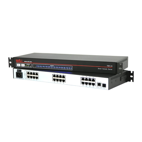
Page 14: Back Panel (Tsm Series)
SETUP LINK PORT 100 - 120V ~ Ethernet 10/100 PHONE 50/60Hz 0.1-0.06A Figure 2.2: Instrument Back Panel (Model TSM-8 Shown) SETUP PORT LINK 100 - 120V ~ 50/60Hz 0.1-0.06A Ethernet 10/100 PHONE Figure 2.3: Instrument Back Panel (Model TSM-24 Shown) - Page 15 PC or other DTE device, please refer to Section 4.5 and Appendix B and Appendix C. • TSM-8 series units include 8 Serial Ports. • TSM-24 series units include 24 Serial Ports. • TSM-40 series units include 40 Serial Ports.
-
Page 16: Back Panel (Tsm-Dps Series And Tsm-Dpe Series)
Unit Description SETUP PORT 100 - 120V ~ 50/60Hz 0.1-0.06A PHONE LINE Ethernet Figure 2.5: Instrument Back Panel (Model TSM-24-DPE) SETUP PORT 100 - 120V ~ 50/60Hz 0.1-0.06A PHONE Ethernet Figure 2.6: Instrument Back Panel (Model TSM-40-DPE) 2.3. Back Panel (TSM-DPS Series and TSM-DPE Series) As shown in Figures 2.5 and 2.6, the TSM-DPS series and TSM-DPE series Back Panel includes the following components: Power Inlets: Two IEC-320-C14 inlets, for connection to your primary and... -
Page 17: Front Panel (Rsm Series)
Unit Description RSM-8 www.wti.com Remote ACTIVITY CLEAR Site Manager Figure 2.7: Instrument Front Panel (Model RSM-8 Shown) 2.4. Front Panel (RSM Series) As shown in Figure 2.7, the RSM front panel includes the following components: CLEAR: Can be used to restart the RSM operating system as described in ... -
Page 18: Back Panel (Rsm Series)
Unit Description PHONE 10/100BaseT SYSTEM SETUP PORTS LINE (DTE) LINK ACTIVITY Figure 2.8: Instrument Back Panel (Model RSM-8) 10/100BaseT PHONE SYSTEM LINE SETUP PORTS (DTE) LINK ACTIVITY Figure 2.9: Instrument Back Panel (Model RSM-16) 2.5. Back Panel (RSM Series) As shown in Figures 2.8 and 2.9, the RSM Back Panel includes the following components: Phone Line Port (Internal Modem Port): When the Internal Modem is present, the ... -
Page 19: Rsm-8R8 Series - Front Panel Components
Unit Description RSM-8R8 www.wti.com SERIAL PORTS LINK SET UP OUTPUT STATUS Remote Site Manager ACTIVITY STATUS RESET DEFAULT Power Control ON RDY DCD PHONE Ethernet 5 6 7 8 9 Figure 2.10: RSM-8R8-1 & RSM-8R8-2 - Front Panel 2.6. RSM-8R8 Series - Front Panel Components As shown in Figure 2.10, the RSM-8R8 series front panel includes the following... -
Page 20: Rsm-8R8-De Series - Front Panel Components
ACTIVITY STATUS Power Control RESET DEFAULT ON RDY DCD www.wti.com PHONE Ethernet 5 6 7 8 9 Figure 2.11: RSM-8R8-DE Series - Front Panel 2.7. RSM-8R8-DE Series - Front Panel Components As shown in Figure 2.11, the RSM-8R8-DE front panel includes the following: Phone Line Port (Internal Modem Port): When the Internal Modem is present, the ... -
Page 21: Rsm-8R8 Series - Back Panel Components
Unit Description PRIMARY SECONDARY Figure 2.12: RSM-8R8-1 - Back Panel PRIMARY SECONDARY Figure 2.13: RSM-8R8-2 - Back Panel 2.8. RSM-8R8 Series - Back Panel Components As shown in Figures 2.12 and 2.13, the RSM-8R8 series back panel includes the following components: Power Inlets: Two IEC-320-C20 inlets, for connection to your primary and ... -
Page 22: Front Panel Button Functions
Unit Description 2.9. Front Panel Button Functions The front panel buttons can be used to perform several functions described below: Notes: • Front Panel button functions can also be disabled via the System Parameters menu, as described in Section 5.3. • When the TSM/RSM is reset to factory defaults, all user-defined configuration parameters will be cleared and the default “super” user account will also be restored. • When the TSM/RSM is reinitialized, all ports will be disconnected. • During the reboot procedure, all port activity LEDs will flash once. Reboot Operating System - Keep User-Defined Parameters: Press and hold the CLEAR (or RESET) button for five seconds, and then release. -
Page 23: Getting Started
3. Getting Started This section describes a simplified installation procedure for the TSM/RSM hardware, which will allow you to communicate with the unit in order to demonstrate basic features and check for proper operation. Note that this Quick Start procedure does not provide a detailed description of unit configuration, or discuss advanced operating features in detail. -
Page 24: Communicating With The Tsm/Rsm
Getting Started 3.3. Communicating with the TSM/RSM When properly installed and configured, the TSM/RSM will allow command mode access via Telnet, Web Browser, SSH client, modem, or local PC. However, in order to ensure security, both Telnet and Web Browser access are disabled in the default state. To enable Telnet and/or Web Browser access, please refer to Section 5.9.2. -
Page 25: Connecting Ports And Switching Outlets
Getting Started Username / Password Prompt: A message will be displayed, which prompts you to enter your username (Login) and password.. The default username is "super" (all lower case, no quotes), and the default password is also "super". If a valid username and password are entered, the TSM/RSM will display either the Main Menu (Web Browser Interface) or the Port Status Screen (SSH, Telnet, or Modem.) Note: • The default Username is "super". - Page 26 If you have further questions regarding the TSM/RSM unit, please contact WTI Customer Support as described in Appendix D.
-
Page 27: Hardware Installation
4. Hardware Installation 4.1. Connecting the Power Supply Cables 4.1.1. Connect the TSM/RSM to Your Power Supply Refer to the cautions listed below and at the beginning of this User's Guide, and then connect the TSM/RSM unit to an appropriate power supply. CAUTIONS: •... -
Page 28: Dc Powered Units
Hardware Installation BUS A BUS B -48V -48V -48V 0.1A Ground Screw Figure 4.1: Terminal Block Assembly (TSM Series, DC Units Only) -48V 0.1A GROUND SCREW -48V -48V Figure 4.2: Terminal Block Assembly (RSM Series, DC Units Only) 4.1.3. DC Powered Units When connecting a DC Powered TSM Series or RSM Series unit to your DC Power source, note that the DC terminal block is designed for connection to two separate power sources. -
Page 29: Connection To Switched Outlets (Rsm-8R8 Series Units Only)
Hardware Installation 4.4. Connection to Switched Outlets (RSM-8R8 Series Units Only) Connect the power cord from your switched device to one of the AC Outlets located on the RSM-8R8 Series unit back panel. Note that when power is applied to the RSM-8R8 Series unit, the AC Outlets will be switched “ON”... -
Page 30: Basic Configuration
5. Basic Configuration This section describes the basic configuration procedure for all TSM/RSM units. For more information on Alarm Configuration, please refer to Section 7. 5.1. Communicating with the TSM/RSM Unit In order to configure the TSM/RSM, you must first connect to the unit, and access command mode. -
Page 31: The Web Browser Interface
Basic Configuration To access command mode via the Text Interface, proceed as follows: Notes: • When communicating with the unit for the first time, you will not be able to contact the unit via Telnet until you have accessed command mode, via Local PC or SSH Client, and used the Network Parameters Menu to enable Telnet as described in Section 5.9. • When connecting your network cable to a TSM/RSM unit that includes two Ethernet ports (e.g., TSM-DPE series or RSM-8R8-DE series) make certain to connect to Port ETH0. Contact the TSM/RSM Unit: Via Local PC: Start your communications program and press [Enter]. Wait for the connect message, then proceed to Step 2. Via Network: The TSM/RSM includes a default IPv4 format IP address (192.168.168.168) and a default IPv4 format subnet mask (255.255.255.0.) This allows you to contact the unit from any network node on the same subnet,... -
Page 32: Access Via Pda
Basic Configuration 5.1.3. Access Via PDA In addition to the Web Browser Interface and Text Interface, the TSM/RSM command mode can also be accessed by PDA devices. Note however, that due to nature of most PDAs, only a limited selection of TSM/RSM operating and status display functions are available to users who communicate with the unit via PDA. -
Page 33: Configuration Menus
Basic Configuration 5.2. Configuration Menus Although the Web Browser Interface and Text Interface (Command Line Interface) provide two separate means for selecting parameters, both interfaces allow access to the same set of basic parameters, and parameters selected via one interface will also be applied to the other. -
Page 34: Defining System Parameters
Basic Configuration 5.3. Defining System Parameters The System Parameters menus are used to define the Site ID Message, set the system clock and calendar, set up log functions and calibrate temperature readings. In the Text Interface, the System Parameters menu is also used to create and manage user accounts and passwords. - Page 35 Basic Configuration • Temperature Format: Determines whether the temperature is displayed as Fahrenheit or Celsius. (Default = Fahrenheit) • Temperature Calibration: Used to calibrate the unit's internal temperature sensing abilities. To calibrate the temperature, place a thermometer inside your equipment rack, in a location that usually experiences the highest temperature. After a few minutes, take a reading from the thermometer, and then key the reading into the configuration menu.
- Page 36 Basic Configuration • Management Utility: Enables/Disables the Device Management Utility (DMU.) When enabled, the DMU allows you to manage multiple WTI units via a single menu. (Default = Off.) For more information on the DMU, please refer to the DMU User's Guide, which can be found on the WTI website at: http://www.wti.com/t-product-manuals.aspx...
-
Page 37: The Real Time Clock And Calendar
Basic Configuration 5.3.1. The Real Time Clock and Calendar The Real Time Clock menu is used to set the TSM/RSM's internal clock and calendar. The configuration menu for the Real Time Clock offers the following options: • Date: Sets the Month, Date, Year and day of the week. •... - Page 38 Basic Configuration • Secondary NTP Address: Defines the IPv4 and/or IPv6 protocol IP address or domain name for the secondary, fallback NTP Server. (Default = undefined) Notes: • In order to use domain names for web addresses, DNS Server parameters must first be defined as described in Section 5.9.5. • The Web Browser Interface includes two separate fields that are allowed to define both an IPv4 protocol and IPv6 protocol format Primary NTP Address and Secondary NTP Address. • When the Primary NTP Address and Secondary NTP Address are defined via the Text Interface, the TSM/RSM will display a prompt that instructs the user to select IPv4 or IPv6 protocol. • The TSM/RSM allows parameters for both IPv4 and IPv6 protocols to be defined and saved. • NTP Timeout: The amount of time in seconds, that will elapse between each attempt to contact the NTP server.
-
Page 39: The Invalid Access Lockout Feature
Basic Configuration 5.3.2. The Invalid Access Lockout Feature When properly configured and enabled, the Invalid Access Lockout feature can watch all login attempts made via SSH connection, Telnet connection, web browser or the serial SetUp Port. If the counter for any of these exceeds the user-defined threshold for maximum invalid attempts, then the corresponding port or protocol will be automatically disabled for the length of time specified by the Lockout Duration parameter. - Page 40 Basic Configuration • SSH Protection: Enables/Disables and configures the Invalid Access function for SSH connections. When this item is enabled and excessive Invalid Access Attempts via SSH are detected, then the TSM/RSM will lock out the offending MAC address for the user-defined SSH Lockout Duration Period or until the /UL command is issued.
- Page 41 Basic Configuration • Web Protection: Enables/Disables and configures the Invalid Access function for Web connections. When this item is enabled and excessive Invalid Access Attempts via Web are detected, then the TSM/RSM will lock out the offending MAC address for the user-defined Web Lockout Duration Period or until the /UL command is issued.
-
Page 42: Log Configuration
Basic Configuration 5.3.3. Log Configuration This feature allows you to create records of command activity, alarm actions and temperature readings for the TSM/RSM unit. The Log features are enabled and configured via the System Parameters Menus. The TSM/RSM features three different event logs: the Audit Log, the Alarm Log and the Temperature Log: •... -
Page 43: The Temperature Log
Basic Configuration 5.3.3.2. The Temperature Log The System Parameters menu allows you to either enable or disable the Temperature Log. When the Temperature Log is disabled, the TSM/RSM will not log temperature readings. In the default state, the Temperature Log is enabled. Note: In RSM-8R8-CM series units, the Temperature Log displayed as a part of the Current Metering Log as described in Section 8.6. -
Page 44: Callback Security
Basic Configuration 5.3.4. Callback Security The Callback function provides an additional layer of security when callers attempt to access command mode via modem. When this function is properly configured, modem users will not be granted immediate access to command mode upon entering a valid password;... -
Page 45: Scripting Options
Basic Configuration • Callback Attempts: The number of times that the TSM/RSM will attempt to contact the Callback number. (Default = 3 attempts) • Callback Delay: The amount of time that the TSM/RSM will wait between Callback attempts. (Default = 30 seconds) Notes: • After configuring and enabling Callback Security, you must then define a callback phone number for each desired user account (as described in... - Page 46 • IPS Mode: This parameter sets up the TSM/RSM for use with command scripts that were written for WTI's IPS Series Remote Reboot Switches. When the IPS Mode is enabled, the "IPS" command prompt will be displayed in the Text Mode, User Accounts will not allow definition of a Username, and only the "password"...
-
Page 47: Automated Mode
Basic Configuration 5.3.5.1. Automated Mode The Automated Mode allows the TSM/RSM to execute switching and reboot commands, without displaying menus or generating response messages. Automated Mode is designed to allow the TSM/RSM to be controlled by a device which can generate commands to control power switching functions without human intervention. -
Page 48: Power Configuration (Rsm-8R8-Cm Series Units Only)
Basic Configuration 5.3.6. Power Configuration (RSM-8R8-CM Series Units Only) The Power Configuration menu allows you to adjust power measurements in order to obtain a more accurate determination of how much "real power" is being used by devices connected to the RSM-8R8-CM Series unit. Real Power is determined by the following equation: (Voltage * Amps) * Power Factor Real Power =... -
Page 49: User Accounts
Basic Configuration 5.4. User Accounts Each time you attempt to access command mode, you will be prompted to enter a username (login) and password. The username and password entered at login determine which serial port(s) and plug(s) you will be allowed to control and what type of commands you will be allowed to invoke. -
Page 50: Granting Serial Port Access
Basic Configuration In the default state, the TSM/RSM includes one predefined account that provides access to Administrator commands and allows to control of all of the TSM/RSM's serial ports and switched power outlets. The default username for this account is "super" (lowercase, no quotation marks), and the password for the account is also "super". -
Page 51: Granting Plug Access (Rsm-8R8 Series Units Only)
Basic Configuration 5.4.3. Granting Plug Access (RSM-8R8 Series Units Only) Each account can be granted access to a different selection of switched power outlets (plugs) and plug groups. When accounts are created, the Plug Access parameter and the Plug Group Access parameter in the Add User menu or Modify User menu can be used to grant or deny access to each plug or plug group by that account. -
Page 52: Managing User Accounts
Basic Configuration 5.5. Managing User Accounts The User Directory function is employed to create new accounts, display parameters for existing accounts, modify accounts and delete accounts. Up to 128 different user accounts can be created. The "User Directory" function is only available when you have logged into command mode using an account that permits Administrator commands. - Page 53 Basic Configuration • Port Access: Determines which TSM/RSM Serial Ports this account will be allowed to access. (Defaults; Administrator & SuperUser = All Ports On, User and ViewOnly = undefined) Notes: • Administrator and SuperUser level accounts will always have access to all Serial Ports. • ViewOnly accounts are allowed to display the status of Serial Ports, but are limited to the ports specified by the account. ViewOnly accounts are not allowed to create connections between ports. • The Port Access parameter is also used to grant or deny user access to the internal modem port. •...
- Page 54 Basic Configuration • Service Access: Determines whether this account will be able to access command mode via Serial Port, Telnet/SSH or Web. For example, if Telnet/SSH Access is disabled for this account, then this account will not be able to access command mode via Telnet or SSH.
-
Page 55: Modifying User Accounts
Basic Configuration 5.5.3. Modifying User Accounts The "Modify User Directory" function allows you to edit existing user accounts in order to change parameters, port and plug access rights or Administrator Command capability. Note that the Modify User function is only available when you have entered command mode using a password that permits Administrator Level commands. -
Page 56: The Plug Group Directory
Basic Configuration 5.6. The Plug Group Directory Note: Power control functions are only available on RSM-8R8 Series units. The Plug Group Directory is not present on standard TSM Series units and standard RSM Series units. The Plug Group Directory allows you to designate "groups" of plugs that are dedicated to a similar function, and will most likely be switched or rebooted all at the same time or controlled by the same type of user account. -
Page 57: Viewing Plug Groups
Basic Configuration 5.6.1. Viewing Plug Groups Note: Power control functions are only available on RSM-8R8 Series units. The Plug Group Directory is not present on standard TSM Series units and standard RSM Series units. The "View Plug Group Directory" option allows you to view the configuration of each Plug Group. Note that the View Plug Group Directory function is only available when you have accessed command mode using a password that permits Administrator Level commands. -
Page 58: Modifying Plug Groups
Basic Configuration 5.6.3. Modifying Plug Groups Note: Power control functions are only available on RSM-8R8 Series units. The Plug Group Directory is not present on standard TSM Series units and standard RSM Series units. The "Modify Plug Group" function allows you to edit existing Plug Groups in order to change plug access rights. Note that this function is only available when you have accessed command mode using a password that permits Administrator Level commands. -
Page 59: Defining Plug Parameters - (Rsm-8R8 Series Units Only)
Basic Configuration 5.7. Defining Plug Parameters - (RSM-8R8 Series Units Only) The Plug Parameters Menu is used to define Plug Names, boot/sequence delay times and Power Up Default values for each of the TSM/RSM's Switched AC Outlets. Note that this function is only available when you have accessed command mode using a password that permits Administrator Level commands. - Page 60 Basic Configuration • Power Up Default: Determines how this plug will react when the "Default All Plugs" command (/DPL) is invoked, or after power to the unit has been interrupted and then restored. After the default command is invoked, or power is restored, the TSM/RSM will automatically switch each plug On or Off as specified by the Power- Up Default.
-
Page 61: The Boot Priority Parameter (Rsm-8R8 Series Units Only)
Basic Configuration 5.7.1. The Boot Priority Parameter (RSM-8R8 Series Units Only) Normally, when an "On" or "Reboot" command is invoked, the TSM/RSM will switch on it's plugs in their default, numeric order. Although in many cases, the default, numeric order will work fine, there are other cases where an individual device (such as a router) must be switched on first, in order to support a second device that will be switched on later. -
Page 62: Example 2: Change Plug 4 To Priority 2
Basic Configuration 5.7.1.2. Example 2: Change Plug 4 to Priority 2 In the second Example shown in Figure 5.2, we start out with Boot Priorities for the plugs set as they were at the end of Example 1; Plug 3 is first, Plug 1 is second, Plug 2 is third and Plug 4 is fourth. -
Page 63: Serial Port Configuration
• If you are configuring the TSM/RSM via modem, modem parameters will not be changed until after you exit command mode and disconnect from the unit. • On TSM-8 Series, RSM-8 Series and RSM-8R8 Series units, Port 9 is the optional Internal Modem Port. -
Page 64: Rs232 Port Modes
Basic Configuration 5.8.1. RS232 Port Modes The TSM/RSM offers four different serial port operation modes: • Any-to-Any Mode: Allows communication between connected ports and permits access to command mode. Any-to-Any Mode Ports can be connected to other Any-to-Any, Passive, Buffer or Modem Mode Ports by invoking the /C command. The Any-to-Any Mode is available to all ports (except the Internal Modem Port) and is the default Port Mode for Port 1. -
Page 65: The Serial Port Configuration Menu
Basic Configuration 5.8.2. The Serial Port Configuration Menu To configure the TSM/RSM's Serial Ports via the Text Interface, type /P n and then press [Enter] (Where n is the name or number of the desired port. To configure the Serial Ports via the Web Browser Interface, click the "Serial Port Configuration"... - Page 66 Basic Configuration • Command Echo: Enables or Disables command echo at this Serial Port. When disabled, commands that are sent to the Serial Port will still be invoked, but the actual keystrokes will not be displayed on your monitor. (Default = On) •...
- Page 67 Basic Configuration Modem Mode: Permits access to command mode and simplifies connection to an external modem. Modem Mode ports can perform all functions normally available in Any-to-Any Mode, but Modem Mode also allows definition of a Hang- Up String, Reset String, and Initialization String: Modem Reset String: Redefines the modem reset string.
- Page 68 Communication alarm to provide notification when a WTI device that has been attached to one of the TSM/RSM's serial ports ceases to function. Normally, the TSM/RSM will send the Heartbeat message to an attached WTI device at regular intervals; if the attached device fails to respond to the Heartbeat message, the TSM/RSM can then notify you via email, Syslog Message or SNMP Trap as described in Section 7.3.
- Page 69 Basic Configuration Network Services: • Direct Connect: Direct Connect allows users to access the TSM/RSM and automatically create a connection between the Network Port and a specific serial port by including the appropriate Telnet port number in the connect command (e.g. Port 5 = 2105). For more information, please refer to Section 10.3. As described below, the Direct Connect feature offers three options.
- Page 70 Basic Configuration • Syslog: The Syslog feature is used to create records of each buffer event. As event records are created, they are sent to a Syslog Daemon, at an IP address defined via the Network Parameters menu. For more information, please refer to Section 11.
- Page 71 Basic Configuration • IP Alias: Assignes an IP address of your choice to the serial port. When an IP address is assigned to the serial port, this essentially allows users to create a direct connection to the serial port without first entering a password. (Default = undefined) Notes: • The IP Alias feature is only available when the Direct Connect feature is set to...
-
Page 72: Copying Parameters To Several Serial Ports (Text Interface Only)
Basic Configuration 5.8.3. Copying Parameters to Several Serial Ports (Text Interface Only) If you are configuring the TSM/RSM via the Text Interface, the /CP (Copy Parameters) command can be used to select identical parameters for one or more serial ports. When the /CP command (Copy Port Parameters) is invoked, the unit will display a menu which allows you to select parameters, and copy them to all or several TSM/RSM serial ports. -
Page 73: Network Configuration
Basic Configuration 5.9. Network Configuration The Network Parameters Menus are used to select parameters and options for the Network Port and also allow you to implement various security and authentication features. To access the Network Parameters menus, proceed as follows: The Network Parameters menu allows you to define the parameters discussed in the following sections. - Page 74 Basic Configuration TSM/RSM Units with Dual Ethernet Ports: Both TSM-DPE series units and RSM-8R8-DE series units include two Ethernet ports. This allows the two ports to either be dedicated to separate applications/users, or employed to provide network fallback capabilities. In cases where the two Ethernet ports will be used for separate applications, a separate IP address is assigned to each port.
-
Page 75: Network Port Parameters
Basic Configuration 5.9.1. Network Port Parameters In the Text Interface, these parameters are found in the main Network Configuration menu In the Web Browser Interface, these parameters are found by placing the cursor over the "Network Configuration" link on the left hand side of the screen, and then clicking on the "Network Port Parameters"... -
Page 76: Network Parameters
Basic Configuration 5.9.2. Network Parameters In the Text Interface, these parameters are accessed via the main Network Configuration menu, which can be activated by typing /N (for IPv4 parameters) or /N6 (for IPv6 parameters) and then pressing [Enter]. In the Web Browser Interface, these parameters are found by placing the cursor over the "Network Configuration"... - Page 77 Basic Configuration • Telnet Access: Enables/disables Telnet access. When Telnet Access is "Off," users will not be allowed to establish a Telnet connection to the unit or initiate outbound Telnet or SSH connections. (Default = On) • Telnet Port: Selects the TCP/IP port number that will be used for Telnet connections.
- Page 78 Basic Configuration • SYSLOG Addresses: Defines the IP addresses for the Syslog Daemon(s) that will receive log records generated by the TSM/RSM. Allows definition of IP addresses for both a primary Syslog Daemon and an optional secondary Syslog Daemon. SYSLOG Addresses can be entered in either IPv4 or IPv6 format, or in domain name format (up to 64 characters.) For more information, please refer to Section 11.
- Page 79 Basic Configuration • Ping Syslog Servers: (Web Browser Interface) Pings the IP addresses which have been defined for the SYSLOG Severs in order to check for a response. Notes: • The Syslog Address submenu in the Text Interface and the Network Parameters submenu in the Web Browser Interface both include a Ping Test function that can be used to ping the user-selected Syslog IP Addresses in order to verify that valid IP addresses have been entered. In order for the Ping Test feature to function, your network and/or firewall must be configured to allow ping commands. • In addition to the Ping Test feature, the /TEST command in the Text Interface or the "Test" option in the Web Browser Interface can also be used to ping the currently defined Syslog Addresses in order to make certain that the IP addresses are responding. 5-50...
-
Page 80: Modem Pooling
Basic Configuration 5.9.2.1. Modem Pooling The "Modem Hunt Telnet" and "Modem Hunt Raw" parameters allow the TSM/RSM to support modem pooling in conjunction with third party Serial Port Redirector software. This allows you to connect external modems to several TSM/RSM serial ports, and then use the TSM/RSM to automatically find a free modem when you need to create an outbound connection. -
Page 81: Ip Security
Basic Configuration 5.9.3. IP Security The IP Security feature allows the TSM/RSM to restrict unauthorized IPv4 or IPv6 format IP addresses from establishing inbound Telnet connections to the unit. This allows you to grant Telnet access to only a specific group of IP addresses, or block a particular IP address completely. -
Page 82: Adding Ip Addresses To The Allow And Deny Lists
Basic Configuration 5.9.3.1. Adding IP Addresses to the Allow and Deny Lists To add an IPv4 or IPv6 format IP Address to the Allow or Deny list, and begin configuring the IP Security feature, proceed as follows. Notes: • Both the Allow and Deny list can include Linux operators, wild cards, and net/mask pairs. • In some cases, it is not necessary to enter all four "digits" of the IP Address. For example, if you wish to allow access to all IP addresses that begin with "192," then you would only need to enter "192." • The IP Security Configuration menu is only available when the Administrator Mode is active. • In order to use domain names in the Allow List and/or Deny List, you must first define IP address(es) for the desired Domain Name Server(s) as described in Section 5.9.5. -
Page 83: Linux Operators And Wild Cards
Basic Configuration 5.9.3.2. Linux Operators and Wild Cards In addition to merely entering a specific IP address or partial IP address in the Allow or Deny list, you may also use any standard Linux operator or wild card. In most cases, the only operator used is "EXCEPT" and the only wild card used is "ALL," but more experienced Linux users may note that other operators and wild cards may also be used. -
Page 84: Static Route
The DNS menu is used to select IPv4 or IPv6 format IP addresses for Domain Name Servers. When web and network addresses are entered, the Domain Name Server interprets domain names (e.g., www.wti.com), and translates them into IP addresses. In the Text Interface, the DNS menu is accessed via the Network Configuration menu. In the Web Browser Interface, the DNS menu is accessed via the flyout menus under the Network Configuration link. -
Page 85: Snmp Access Parameters
Basic Configuration 5.9.6. SNMP Access Parameters These menus are used to select access parameters for the SNMP feature. In the Text Interface, the SNMP Access Parameters menu is accessed via the Network Configuration menu. In the Web Browser Interface, the SNMP Access Parameters menu is accessed via the flyout menus under the Network Configuration link. - Page 86 Basic Configuration • SNMPv3 User Name: Sets the User Name for SNMPv3. Note that this option is not available when the Version parameter is set to V1/V2. (Default = undefined) • SNMPv3 Password: Sets the password for SNMPv3. Note that this option is not available when the Version parameter is set to V1/V2.
-
Page 87: Snmp Trap Parameters
Basic Configuration 5.9.7. SNMP Trap Parameters These menus are used to select parameters that will be used when SNMP traps are sent. For more information on SNMP Traps, please refer to Section 12. In the Text Interface, the SNMP Trap Parameters menu is accessed via the Network Configuration menu. -
Page 88: Ldap Parameters
Basic Configuration 5.9.8. LDAP Parameters The TSM/RSM supports LDAP (Lightweight Directory Access Protocol,) which allows authentication via the "Active Directory" network Directory Service. When LDAP is enabled, command access rights can be granted to new users without the need to define individual new accounts at each TSM/RSM unit, and existing users can also be removed without the need to delete the account from each TSM/RSM unit. - Page 89 Basic Configuration • LDAP Port: Defines the port that will be used to communicate with the LDAP server. (Default = 389) • TLS/SSL: Enables/Disables TLS/SSL encryption. Note that when TLS/SSL encryption is enabled, the LDAP Port should be set to 636. (Default = Off) •...
-
Page 90: Adding Ldap Groups
Basic Configuration • Debug: This option is used to assist WTI Technical Support personnel with the diagnosis of LDAP issues. (Default = Off) • Ping Test: Allows you to ping IP addresses or domain names that have been defined via the LDAP Parameters menus in order to check that a valid IP address or domain name has been entered. -
Page 91: Viewing Ldap Groups
Basic Configuration • Plug Group Access: (RSM-8R8 Series Units Only) This item is used to determine which plug groups the members of this LDAP Group will be allowed to control. (Default = undefined) • Service Access: This item determines how members of this LDAP Group will be allowed to access command mode. -
Page 92: Tacacs Parameters
Basic Configuration 5.9.9. TACACS Parameters The TACACS Configuration Menus offer the following options: • Enable: Enables/disables the TACACS feature at the Network Port. (Default = Off) • Primary Address: The IP address or domain name for your primary TACACS server. (Default = undefined) •... - Page 93 Basic Configuration Port Access: Determines the default Port Access setting for new TACACS users. The Port Access setting determines which serial ports each account will be allowed to control. (Defaults; Administrator and SuperUser = All Ports On, User = undefined, ViewOnly = undefined) Notes: • Administrator and SuperUser level accounts always have access to all ports.
- Page 94 Basic Configuration Service Access: Selects the default Service Access setting for new TACACS users. The Service Access setting determines whether each account will be able to access command mode via Serial Port, Telnet/SSH or Web. For example, if Telnet/SSH Access is disabled for an account, then the account will not be able to access command mode via Telnet or SSH.
-
Page 95: Radius Parameters
Basic Configuration 5.9.10. RADIUS Parameters In the Text Interface, the RADIUS Parameters menu is accessed via the Network Configuration menu (/N for IPv4 parameters or /N6 for IPv6 parameters.) In the Web Browser Interface, both IPv4 and IPv6 parameters are defined via a single RADIUS Parameters menu, which is accessed via the flyout menus under the Network Configuration link. -
Page 96: Dictionary Support For Radius
RADIUS dictionary file. The WTI RADIUS dictionary file provides the following commands: • WTI-Super - Sets the command access level for the user. This command provides the following arguments: 0 = ViewOnly... - Page 97 Basic Configuration • WTI-Port-Access - Determines which port(s) the user will be allowed to access. This command provides an argument that consists of an 8 character string, with one character for each TSM/RSM Serial Port. The following options are available...
-
Page 98: Email Messaging Parameters
Basic Configuration 5.9.11. Email Messaging Parameters The Email Messaging menu is used to define parameters for email messages that the TSM/RSM can send to notify you when an alarm is triggered. To define email message parameters, access the TSM/RSM Command Mode using a password that permits access to Administrator Level commands and then proceed as follows: •... -
Page 99: Save User Selected Parameters
Basic Configuration 5.10. Save User Selected Parameters It is strongly recommended to save all user-defined parameters to a file as described in Section 15. This will allow quick recovery in the event of accidental deletion or reconfiguration of port parameters. When changing configuration parameters via the Text Interface, make certain that the TSM/RSM has saved the newly defined parameters before exiting from command mode. -
Page 100: Reboot Options
6. Reboot Options In addition to performing reboot cycles in response to commands, RSM-8R8 Series units can also be configured to automatically reboot outlets when an attached device does not respond to a Ping command (Ping-No-Answer Reboot) or according to a user defined schedule (Scheduled Reboot.) Note: Power switching and reboot functions are only available on RSM-8R8 Series units. Power switching and reboot functions are not supported on... -
Page 101: Ping-No-Answer Reboot
Reboot Options 6.1. Ping-No-Answer Reboot A Ping-No-Answer Reboot can be used to reboot one or more outlets when an attached device does not respond to a Ping Command. In addition, the Ping-No-Answer Reboot feature can also be configured to send an email, Syslog Message or SNMP Trap to notify you whenever a Ping-No-Answer Reboot occurs. - Page 102 Reboot Options • Interval After Failed Ping: Determines how often the Ping command will be sent after a previous Ping command receives no response. (Default = 10 Seconds) • Ping Delay After PNA Action: Determines how long the RSM-8R8 Series unit will wait to send additional Ping commands, after a Ping-No-Answer Reboot has been initiated.
-
Page 103: Viewing Ping-No-Answer Reboot Profiles
Reboot Options • Ping Test: Sends a test Ping command to the IP Address or domain name that has been defined for this Ping-No-Answer Reboot. Notes: • In order for the Ping Test function to work properly, your network and/or firewall as well as the device at the target IP address must be configured to allow ping commands. • After you have finished defining or editing Ping-No-Answer Reboot parameters, make certain to save the changes before proceeding. In the Web Browser Interface, click on the "Add Ping No Answer" button to save parameters; in the Text Interface, press the [Esc] key several times until the RSM-8R8 Series unit displays the "Saving Configuration" message and the cursor returns to the command prompt. 6.1.2. Viewing Ping-No-Answer Reboot Profiles After you have defined one or more Ping-No-Answer Reboot profiles, you can review the parameters selected for each profile using the View Ping-No-Answer feature. -
Page 104: Scheduled Reboot
Reboot Options 6.2. Scheduled Reboot The Scheduled Reboot feature can be used to reboot one or more outlets according to a user-defined schedule, or to automatically turn outlets Off and then On according to a user defined schedule. In order to configure a Scheduled Reboot, you must access command mode using a password that permits access to Administrator level commands. -
Page 105: Viewing Scheduled Reboot Actions
Reboot Options • Plug Access: Determines which outlet(s) this Scheduled Reboot action will be applied to. In the Text Interface, key in the number for the Plug Access option, press [Enter] and then following the instructions in the resulting submenu. In the Web Browser Interface, outlets are designated by clicking on the "plus"... -
Page 106: Alarm Configuration
7. Alarm Configuration When properly configured, the TSM/RSM can monitor temperature readings, ping command response and a number of other factors at network installation sites and log this information for future review. When any monitored condition exceeds user- defined trigger levels, the TSM/RSM can also notify support personnel via Email, Syslog Message or SNMP trap. -
Page 107: The Over Current Alarms (Rsm-8R8-Cm Series Only)
Alarm Configuration 7.1. The Over Current Alarms (RSM-8R8-CM Series Only) The Over Current Alarms are designed to inform you when current consumption reaches or exceeds user-defined levels. Depending on the specific RSM-8R8-CM model, RSM- 8R8-CM units can have up to four Over Current Alarms (two sets of two alarms): •... - Page 108 Alarm Configuration The Current Alarm Configuration menus offer the following parameters: • Trigger Enable: Enables/Disables the trigger for this alarm. When Disabled, this alarm will be suppressed. (Default = On) Notes: • When an alarm is generated, to cancel an alarm without correcting the condition that caused the alarm, simply toggle the Trigger Enable parameter Off and then back On again. • The Trigger Enable, Notify on Clear, Email Message and Address 1, 2 and 3 Parameters all include "Copy to All Triggers" options that allow you to enable/ disable the corresponding parameter for all other alarms. For example, if the Over Current Alarm's Trigger Enable parameter is set to "On (Copy to All Triggers), then the triggers for all other TSM/RSM alarms will also be enabled. •...
-
Page 109: Over Current Alarms - Load Shedding And Auto Recovery
Alarm Configuration • Load Shedding: Provides access to a submenu which is used to configure and enable the Load Shedding feature for the Over Current Alarm. When Load Shedding is enabled and properly configured, the RSM-8R8-CM will switch user-selected plugs On or Off whenever the current load exceeds the Alarm Set Threshold value. - Page 110 Alarm Configuration • Auto Recovery: Enables/Disables the Auto Recovery feature for the selected branch or line. When both Load Shedding and Auto Recovery are enabled, the RSM-8R8-CM will return plugs to their former On/Off state after current load falls below the Alarm Clear Threshold value. This allows the RSM-8R8-CM to "undo" the effects of Load Shedding after current load has returned to an acceptable level.
-
Page 111: The Over Temperature Alarms
Alarm Configuration 7.2. The Over Temperature Alarms The Over Temperature Alarms can inform you when temperatures inside your equipment rack reach or exceed user specified trigger levels. There are two separate Over Temperature Alarms; the Initial Threshold alarm and the Critical Threshold Alarm. Typically, the Initial Threshold alarm is used to provide notification when temperatures reach a point where you might want to investigate, whereas the Critical Threshold alarm is used to provide notification when temperatures approach a level that may harm... - Page 112 Alarm Configuration • Alarm Set Threshold: The trigger level for this alarm. When temperature exceeds the Alarm Set Threshold, the TSM/RSM can send an alarm (if enabled) and/or begin Load Shedding (if enabled.) For more information on Load Shedding, please refer to Section 7.2.1. (Initial Threshold: Default = 90°F or 32°C, Critical Threshold: Default = 100°F or 38°C) Note: The Alarm Set Threshold value must be greater than the Alarm Clear Threshold value. The TSM/RSM will not allow you to define an Alarm Clear...
-
Page 113: Over Temperature Alarms - Load Shedding And Auto Recovery
Alarm Configuration • Load Shedding: (RSM-8R8 Series Units Only) Provides access to a submenu, which is used to configure and enable the Load Shedding feature for the Over Temperature alarms. When Load Shedding is enabled and properly configured, RSM-8R8 Series units can switch specific, user-selected plugs On or Off whenever the temperature exceeds the Alarm Set Threshold value. - Page 114 Alarm Configuration • Plug Access: Determines which Plug(s) will be switched when the temperature exceeds the Alarm Set Threshold and the Load Shedding feature is triggered. For example, if plugs 1, 2 and 3 are selected, then these plugs will be switched On or Off whenever the temperature exceeds the Alarm Set Threshold.
-
Page 115: The Lost Communication Alarm
7.3. The Lost Communication Alarm The Lost Communication with Unit Alarm is intended to provide prompt notification when communication with an attached WTI device is disrupted. When the Lost Communication Alarm is triggered, the TSM/RSM can provide notification via Email, Syslog Message or SNMP Trap. - Page 116 For example, when Notify Upon Clear is enabled, the TSM/RSM will send initial notification when it detects lost communication with the a WTI device connected to one of the TSM/RSM Serial Ports, and then send a second notification when it determines that communication has been restored.
-
Page 117: The Ping-No-Answer Alarm
Alarm Configuration 7.4. The Ping-No-Answer Alarm The Ping-No-Answer Alarm can be used to provide notification when a device at a target IP address fails to respond to a ping command. When properly configured and enabled, the Ping-No-Answer Alarm can promptly notify network administrators and support personnel when a target device appears to have malfunctioned, allowing quick response to equipment problems that could potentially interfere with network communication. - Page 118 Alarm Configuration Note that both the Text Interface and the Web Browser Interface include menu options that allow you to either View previously defined Ping No Answer IP Addresses, add new Ping No Answer Addresses, Modify previously defined Ping No Answer IP Addresses or delete previously defined Ping No Anser IP addresses.
-
Page 119: Tsm And Rsm Series Units
Alarm Configuration • Ping Test: (Text Interface Only) Sends a test Ping command to this IP Address. Notes: • In order for the Ping Test feature to work properly, your network and/or firewall, as well as the device at the target IP address, must be configured to allow ping commands. • After defining or editing Ping No Answer IP Addresses, make certain to save the changes before proceeding. In the Web Browser Interface, click on the "Add Ping No Answer" button to save parameters; in the Text Interface, press the [Esc] key several times until the "Saving Configuration" message is displayed and the cursor returns to the command prompt. 7.4.1.2. Configuring the Ping No Answer Alarm - TSM and RSM Series Units To configure the Ping-No-Answer Alarm, you must access command mode using a password that permits Administrator Level commands. -
Page 120: Ping-No-Answer Alarm - Rsm-8R8 Series Units
Alarm Configuration • Email Message: Enables/Disables email notification for this alarm. (Default = On) • Address 1, 2, and 3: These parameters are used to select which of the three email addresses defined via the "Email Messages" menu (see Section 5.9.11) will receive the email alarm notification messages generated by this alarm. The Address parameters can be used to select one, or any combination of the addresses defined via the Email Messages menu. - Page 121 Alarm Configuration To configure the Ping-No-Answer Alarm, you must access the RSM-8R8 command mode using a password that permits Administrator Level commands. Up to 54 Ping-No- Answer IP Addresses can be defined. The Add Ping-No-Answer menu is used to define the following parameters for each new Ping-No-Answer IP Address: •...
-
Page 122: The Serial Port Invalid Access Lockout Alarm
Alarm Configuration 7.5. The Serial Port Invalid Access Lockout Alarm The Serial Port Invalid Access Lockout Alarm can provide notification when the TSM/RSM has locked the serial ports due to repeated, invalid attempts to access command mode via serial port. Normally, the Invalid Access Lockout feature (discussed in Section 5.3.2) can lock the serial ports whenever the unit detects that the user-defined threshold for invalid access attempts has been exceeded. - Page 123 Alarm Configuration • Resend Delay: Determines how long the TSM/RSM will wait to resend an email message generated by this alarm, when the initial attempt to send the notification was unsuccessful. (Default = 60 Minutes) • Notify Upon Clear: When this item is enabled, the TSM/RSM will send additional notification when the situation that caused the alarm has been corrected.
-
Page 124: The Power Cycle Alarm
Alarm Configuration The Power Cycle Alarm The Power Cycle Alarm can provide notification when all input power to the TSM/RSM unit is lost and then restored. When the power supply is lost and then restored, the TSM/RSM can provide notification via Email, Syslog Message or SNMP Trap. Notes: • The Power Cycle alarm can provide notification when all input power to the TSM/RSM unit is lost and then restored. This alarm will not function in dual... -
Page 125: Buffer Threshold Alarm
Alarm Configuration 7.7. Buffer Threshold Alarm The Buffer Threshold Alarm can provide notification when the amount of data stored in the buffer for a given serial port exceeds the Buffer Threshold value that has been defined for that port as described in Section 5.8.2. When the amount of data in the buffer for a given serial port exceeds the user-defined Buffer Threshold value, the TSM/RSM can provide notification via Email, Syslog Message or SNMP Trap. - Page 126 Alarm Configuration • Notify Upon Clear: When this item is enabled, the TSM/RSM will send additional notification when the situation that caused the alarm has been corrected. For example, when Notify Upon Clear is enabled for the Buffer Threshold Alarm, the TSM/RSM will send initial notification when it detects that the amount of data stored in the buffer for a given serial port has exceeded the user-defined Buffer Threshold value, and then send a second notification when it determines that the amount of data in the buffer has fallen below the Buffer Threshold value.
-
Page 127: The Plug Current Alarm (Rsm-8R8-Cm Series Only)
Alarm Configuration 7.8. The Plug Current Alarm (RSM-8R8-CM Series Only) The Plug Current Alarm allows you to monitor current consumption at each of the RSM-8R8-CM's switched outlets and generate an alarm when current exceeds a user- defined "High" threshold or falls below a user-defined "Low" threshold. The Plug Current Alarm can also be applied to user-defined Plug Groups in order to generate an alarm when total current consumption for the given Plug Group rises too high or falls too low. - Page 128 Alarm Configuration • Plug Thresholds: Defines current consumption level(s) that will trigger alarm(s) at each switched outlet. The Plug Thresholds can be configured to trigger an alarm when current consumption rises above a user-defined "High" value and/or when current consumption falls below a user-defined "Low" value. This allows you to define a "normal"...
- Page 129 Alarm Configuration • Email Message: Enables/Disables email notification for this alarm. (Default = On) • Address 1, 2, and 3: These parameters are used to select which of the three email addresses defined via the "Email Messages" menu (see Section 5.9.11) will receive the email alarm notification messages generated by this alarm. The Address parameters can be used to select one, or any combination of the addresses defined via the Email Messages menu.
-
Page 130: The No Dialtone Alarm
Alarm Configuration 7.9. The No Dialtone Alarm The No Dialtone Alarm enables the TSM/RSM to monitor a telephone line connected to an external modem installed at the TSM/RSM Setup Port, and then provide notification if the TSM/RSM detects that the phone line is dead or no dialtone is present. If the No Dialtone Alarm is enabled and the TSM/RSM determines that there is no dialtone signal, the No Dialtone Alarm can provide notification via email using a network connection. - Page 131 Alarm Configuration • Notify Upon Clear: When this item is enabled, the TSM/RSM will send additional notification when the situation that caused the alarm has been corrected. For example, when Notify Upon Clear is enabled, the TSM/RSM will send initial notification when it detects that the dialtone for the external modem has been lost, and then send a second notification when it determines that the dialtone has been restored.
-
Page 132: The Lost Voltage Alarm (Dual Power Inlet Units Only)
Alarm Configuration 7.10. The Lost Voltage Alarm (Dual Power Inlet Units Only) The Lost Voltage (Line In) Alarm can provide notification when one of the two power supplies available to a dual power inlet unit is interrupted. Notes: • The Lost Voltage (Line In) alarm is only available on TSM/RSM units that include two input power lines (TSM-DPS Series units and RSM-8R8 Series units.) • The Lost Voltage (Line In) alarm will provide notification when one of the two... - Page 133 Alarm Configuration • Notify Upon Clear: When enabled, the TSM/RSM will send additional notification when the situation that caused the alarm has been corrected. For example, when Notify Upon Clear is enabled, the TSM/RSM will send initial notification when it detects that one of it's power supplies has been lost or disconnected, and then send a second notification when it determines that power has been restored.
-
Page 134: The Status Screens
/J * and then press [Enter]. To display the Product Status Screen via the Web Browser Interface, click on the "Product Status" link. Note: The Information provided by the Product Status Screen is intended mainly to assist WTI support peronnel with the diagnosis of user equipment problems. 8.2. The Network Status Screen The Network Status screen shows activity at the TSM/RSM's 16 virtual network ports. To view the Network Status Screen, you must access command mode using a password that permits access to Administrator Level commands. -
Page 135: The Port Status Screen
To view the Port Status Screen via the Text Interface, type /S and press [Enter]. To view the Port Status Screen via the Web Browser Interface, Click on the "Port Status" link on the left hand side of the screen. Notes: • On TSM-8 Series, RSM-8 Series and RSM-8R8 Series units, Port 9 is the Internal Modem Port. • On RSM-16 Series units, Port 17 is the Internal Modem Port. • On TSM-24 Series units, Port 25 is the Internal Modem Port. -
Page 136: The Port And Plug Status Screens (Rsm-8R8 Series Units Only)
The Status Screens 8.4. The Port and Plug Status Screens (RSM-8R8 Series Units Only) The Port Status screen and Plug Status screen show the status of the RSM-8R8 Series unit's serial ports and switched plugs. The Port Status screen lists the user-defined port name and port mode for each serial port, as well as the buffer count, connection status and the names of any user's currently accessing these ports. -
Page 137: The Plug Group Status Screen (Rsm-8R8 Series Units Only)
The Status Screens 8.5. The Plug Group Status Screen (RSM-8R8 Series Units Only) The Plug Group Status screen shows the configuration details and On/Off status for the RSM-8R8 Series unit's user-defined Plug Groups. Notes: • The Plug Group Status Screen is not included on standard TSM Series units and standard RSM Series units. • When the Plug Group Status Screen is viewed by an account with Administrator or SuperUser command access, all plugs and plug groups can be shown. When the Plug Status Screen is viewed by an account with User or ViewOnly command access, then the unit will only display the plugs and plug groups that are allowed by that account. -
Page 138: The Current Metering Status Screen (Rsm-8R8-Cm Series Only)
The Status Screens 8.6. The Current Metering Status Screen (RSM-8R8-CM Series Only) The Current Metering Status screen is primarily intended to be used to display up-to- date readings for Amps, Watts, Voltage and temperature for the RSM-8R8-CM Series unit. To view the Current Metering Log screen, proceed as follows: Note: Current and Power Monitoring features are not available on standard TSM units or standard RSM units. -
Page 139: The Current History Screen (Rsm-8R8-Cm Series Only)
The Status Screens 8.7. The Current History Screen (RSM-8R8-CM Series Only) The Current History Screen displays current, voltage and temperature readings as a function of time. In the Web Browser Interface, the Current History can be displayed as a graph or downloaded in ASCII, CSV or XML format. In the Text Interface, the Current History can be displayed as straight ASCII data, or can be downloaded in CSV or XML format. -
Page 140: The Power Range Status Screen (Rsm-8R8-Cm Series Only)
The Status Screens 8.8. The Power Range Status Screen (RSM-8R8-CM Series Only) The Power Range Status Screen can be used to display power consumption readings over a user-selected period of time, for the RSM-8R8-CM series unit. Note: Current and Power Monitoring features are not available on standard TSM series units or standard RSM series units. To view the Power Range Status Screen, access command mode using an account that permits access to Administrator or SuperUser level commands and then proceed as follows: Text Interface:... -
Page 141: The Power History Screen (Rsm-8R8-Cm Series Only)
The Status Screens 8.9. The Power History Screen (RSM-8R8-CM Series Only) The Power History Screen shows power consumption versus time. To view the Power History Screen, access the command mode using an account that permits access to Administrator or SuperUser level commands, and then proceed as follows: Note: Current and Power Monitoring features are not available on standard TSM series units or standard RSM series units. -
Page 142: The Port Diagnostics Screen
The Status Screens 8.10. The Port Diagnostics Screen The Port Diagnostics Screen provides more detailed information about each port. To display the Port Diagnostics Screen, access the Text Interface command mode and type /SD [Enter]. Note: The Port Diagnostics Screen is only available via the Text Interface. When the /SD command is invoked by an Administrator or SuperUser level account, the Port Diagnostics Screen will display the status of all ports. -
Page 143: The Port Parameters Screens
The Status Screens 8.12. The Port Parameters Screens The /W (Who) command displays more detailed information about an individual TSM/RSM port. Rather than listing general connection information for all ports, the Port Parameters screen lists all defined parameters for a specific port. When the /W command is invoked by an Administrator or SuperUser level account, it can be used to display parameters for all TSM/RSM Serial Ports, plus the Network Port. -
Page 144: The Event Logs
The Status Screens 8.13. The Event Logs The Event Logs can be used to review recent user activity, alarm events and temperature trends that have been recorded by the TSM/RSM unit. In order to view, download or erase the event logs, you must access command mode using a password that permits Administrator or SuperUser level commands. -
Page 145: Operation
9. Operation As discussed in Section 5.1, the TSM/RSM offers two separate command interfaces; the Web Browser Interface and the Text Interface. Both interfaces offer essentially the same options and features, and in most cases, parameters defined via the Web Browser Interface will also apply when communicating via the Text Interface (and vice versa.) 9.1. -
Page 146: Connecting Ports - Text Interface
Operation 9.1.1.1. Connecting Ports - Text Interface Two different types of connections can be made between TSM/RSM serial ports; Resident Connections and Third Party Connections The TSM/RSM allows communication between devices without the requirement that both ports use the same communication parameters. • Resident Connections: Your resident port issues a /C command to connect to a second port. - Page 147 Operation To Connect ports using the Text Interface, proceed as follows: Access command mode via the Text Interface. Invoke the /C command to connect the desired ports. Resident Connect: To connect your resident port to another port, type /C xx [Enter]. Where xx is the number or name of the port you want to connect. The TSM/RSM will display the numbers of the connected ports, along with the command required in order to disconnect the two ports.
-
Page 148: Disconnecting Ports - Text Interface
Operation 9.1.1.2. Disconnecting Ports - Text Interface The Text Interface provides three different methods for disconnecting ports, the Resident Disconnect, the Third Party Disconnect, and the No Activity Timeout. Providing the Timeout feature is enabled, a No Activity Timeout will disconnect resident ports or third party ports. - Page 149 Operation The /D command can also disconnect a remote user from the Network Port. This is useful in cases where a user has unsuccessfully disconnected via Telnet, and you can’t wait for the TSM/RSM to timeout in order to free up the TCP port.
-
Page 150: The Port Control Screen - Web Browser Interface
Operation 9.1.1.3. The Port Control Screen - Web Browser Interface In the Web Browser Interface, the Port Control Screen can be used to disconnect TSM/RSM serial ports that have been connected using the /C command in the Text Interface as described in Section 9.1.1.1. To disconnect ports using the Port Control Screen, first access the TSM/RSM Command Mode via the Web Browser Interface as described in Section 5.1. -
Page 151: Defining Hunt Groups - Text Interface
Operation 9.1.1.4. Defining Hunt Groups - Text Interface A Hunt Group creates a situation where the TSM/RSM will scan a group of similarly named ports and connect to the first available port in the group. Hunt Groups are created by assigning identical or similar names to two or more ports. Hunt Groups can be defined using Any-to-Any, Passive, Buffer, or Modem Mode Ports. -
Page 152: Passive Mode
Operation 9.1.2. Passive Mode Passive Mode Ports function the same as Any-to-Any Mode Ports, but do not allow access to command mode. A Passive Mode Port can be connected to other serial ports, but cannot enter command mode, and therefore cannot be used to define parameters, display status, or invoke commands to connect ports or control power switching. - Page 153 Operation If the buffer contains data, the TSM/RSM will display a prompt that offers the following options: • Display One Screen: To send data one screen at a time, press [Enter]. Each time [Enter] is pressed, the next screen is sent. • Display All Data: To send all data currently stored in the buffer, type 1 and press [Enter].
-
Page 154: Port Buffers
Operation 9.1.3.2. Port Buffers The Status Screen lists the amount of Buffer Memory currently used by each port. The TSM/RSM uses buffer memory in two different ways, depending on the user-selected port mode. • Any-to-Any, Passive, and Modem Mode Ports: When two ports are communicating at dissimilar baud rates, the buffer memory prevents data overflow at the slower port. -
Page 155: Modem Mode
Operation 9.1.4. Modem Mode The Modem Mode provides features specifically related to modem communication. A Modem Mode Port can perform all functions normally available in Any-to-Any Mode. The Modem Mode is available at all TSM/RSM ports except the Network Port. When a call is received, the unit will prompt the caller to enter a username and password. -
Page 156: Controlling Power - Web Browser Interface (Rsm-8R8 Series Only)
Operation 9.2. Controlling Power - Web Browser Interface (RSM-8R8 Series Only) Note: Power switching and reboot functions are only available on RSM-8R8 Series units. Standard TSM Series units and standard RSM Series units do not support power control functions. When using the Web Browser Interface, switching commands are invoked via the Plug Control Screen and Plug Group Control Screen. 9.2.1. The Plug Control Screen - Web Browser Interface Note: Power switching and reboot functions are only available on RSM-8R8 Series units. Standard TSM Series units and RSM Series units do not support power control functions. -
Page 157: The Plug Group Control Screen - Web Browser Interface
Operation 9.2.2. The Plug Group Control Screen - Web Browser Interface Note: Power switching and reboot functions are only available on RSM-8R8 Series units. Standard TSM Series units and RSM Series units do not support power control functions. The Plug Group Control Screen is used to send switching and reboot commands to the user-defined Plug Groups. As described in Section 5.6, Plug Groups allow you to specify a group of outlets that are dedicated to a similar purpose or client, and then direct switching commands to the group, rather than switching one plug at a time. -
Page 158: Controlling Power - Text Interface (Rsm-8R8 Series Units Only)
Operation 9.3. Controlling Power - Text Interface (RSM-8R8 Series Units Only) Note: Power switching and reboot functions are only available on RSM-8R8 Series units. Standard TSM Series units and standard RSM Series units do not support power control functions. When using the Text Interface, all serial port connection and power switching functions are performed by invoking simple, ASCII commands. ASCII commands are also used to display status screens and to log out of command mode. The Text Interface includes a Help Menu, which summarizes all available commands. -
Page 159: Switching And Reboot Commands - Text Interface
Operation 9.3.2. Switching and Reboot Commands - Text Interface Note: Power switching and reboot functions are only available on RSM-8R8 Series units. Standard TSM Series units and standard RSM Series units do not support power control functions. These commands can be used to switch or reboot the RSM-8R8 Series unit’s switched plugs, and can also be used to set plugs to the user-defined Power-Up Default values. Plugs may be specified by name or number. - Page 160 Operation Switch Plug(s) Off: To power-off a plug or Plug Group, type /OFF n and press [Enter]. Where "n" is the number or name of the desired plug or Plug Group. Note that the “/OFF” command can also be entered as “/OF”. For example: /OFF 2 [Enter] or /OF ROUTER [Enter] Reboot Plug(s): To initiate a Boot cycle, type /BOOT n and press [Enter].
-
Page 161: Applying Commands To Several Plugs - Text Interface
Operation 9.3.2.1. Applying Commands to Several Plugs - Text Interface Note: Power switching and reboot functions are only available on RSM-8R8 Series units. Standard TSM Series units and RSM Series units do not support power control functions. As described below, switching and reboot commands can be applied to only one Switched AC Outlet, or to an assortment of outlets. Note: When switching and reboot operations are initiated, Boot/Sequence Delay times and user-defined Plug Priority values will be applied as described in Section 5.7. Switch Several Plugs: To apply a command to several plugs, enter the numbers or names for the plugs, separated by a "plus sign"... -
Page 162: The Ssh/Telnet Connect Function (Web Browser Interface Only)
Operation 9.4. The SSH/Telnet Connect Function (Web Browser Interface Only) The SSH/Telnet Connect function allows you to open an SSH Shell Session or Telnet Session without leaving the Web Browser interface. Once you have successfully opened an SSH Shell Session or Telnet Session, you can then use ASCII commands to configure and operate the TSM/RSM using the commands described in Section 17. -
Page 163: Initiating A Telnet Session Via The Web Browser Interface
Operation 9.4.2. Initiating a Telnet Session via the Web Browser Interface To initiate a Telnet Session from the TSM/RSM Web Browser Interface, proceed as follows: Place the cursor over the "SSH/Telnet Connect" button on the left hand side of the screen. -
Page 164: Manual Operation
Operation 9.5. Manual Operation In addition to the command driven functions available via the Web Browser Interface and Text Interface, some TSM/RSM functions can also be controlled manually. For a summary of front panel control functions, please refer to Section 2.9. 9.6. -
Page 165: Telnet & Ssh Functions
10. Telnet & SSH Functions 10.1. Network Port Numbers Whenever an inbound Telnet or SSH session connects to an TSM/RSM serial port, the Port Status Screen and Port Diagnostics Screen will indicate that the serial port is presently connected to Port "Nn" (where "N" indicates a network connection, and "n" is a number that lists the logical Network Port being used;... -
Page 166: The Direct Connect Feature
Telnet & SSH Functions 10.3. The Direct Connect Feature The Direct Connect feature allows you to initiate a Telnet, SSH or Raw Socket session with the TSM/RSM and make an immediate connection to a specific serial port of your choice, without first being presented with the command interface. This allows you to connect to a TCP port that is mapped directly to one of the TSM/RSM's serial ports. - Page 167 Telnet & SSH Functions OFF - Break on Raw Disconnect: When the Direct Connect option has been enabled as described in Steps 2 or 3 above, this option can be used to configure the TSM/RSM to send a break character whenever a Raw Socket connection to this port is terminated.
-
Page 168: Connecting To A Serial Port Using Direct Connect
10.3.3. Connecting to a Serial Port using Direct Connect Direct Connect TCP port numbers are as follows: Standard Telnet Direct Connection (with Password): RSM-8 Series, TSM-8 Series and RSM-8R8 Series units: • Serial Ports: TCP port numbers 2101 through 2108. • Internal Modem Port: TCP port number 2109. - Page 169 Telnet & SSH Functions Raw Socket Direct Connection (with Password): RSM-8 Series, TSM-8 Series and RSM-8R8 Series units: • Serial Ports: TCP port numbers 3101 through 3108. • Internal Modem Port: TCP port number 3109. RSM-16 Series units: • Serial Ports: TCP port numbers 3101 through 3116.
-
Page 170: Terminating A Direct Connect Session
Telnet & SSH Functions Connection Example Assume that Port 8 is configured as described in Section 10.3.2 If the TSM/RSM’s IP address is "1.2.3.4", and you wish to establish a standard Telnet protocol connection with port 8 (TCP Port Number 2108), then on a UNIX system, the connect command would be invoked as follows: $ telnet 1.2.3.4 2108 [Enter] The TSM/RSM will first send the site ID, Port Number, Port Name, and Telnet Port... -
Page 171: Ip Aliasing
Telnet & SSH Functions 10.4. IP Aliasing In addition to the Direct Connect function described in Section 10.3, the TSM/RSM also supports IP Aliasing, which provides another method for connecting directly to any serial port on the unit without first accessing the command interface. IP Aliasing allows you to assign an IP address to a TSM/RSM serial port, and then connect to that port directly via Telnet, SSH or Raw Socket. -
Page 172: Creating An Outbound Telnet Connection
Telnet & SSH Functions 10.5. Creating an Outbound Telnet Connection The TSM/RSM includes a /TELNET command, that can be used to create an outbound Telnet connection. In order to use the /TELNET command, you must access the TSM/RSM's Text Interface command mode using an account that permits Telnet Access and Outbound Access, via one of the TSM/RSM's Serial RS232 Ports as described below. -
Page 173: Creating An Outbound Ssh Connection
Telnet & SSH Functions 10.6. Creating an Outbound SSH Connection The TSM/RSM's /SSH command can be used to create an outbound SSH connection. In order to use the /SSH command, you must access the TSM/RSM's Text Interface command mode using an account that permits SSH Access and Outbound Access, via one of the TSM/RSM's Serial RS232 Ports as described below. -
Page 174: Syslog Messages
11. Syslog Messages The Syslog feature can create log records of each Alarm Event. As these event records are created, they are sent to a Syslog Daemon, located at an IP address defined via the Network Parameters menu. 11.1. Configuration In order to employ this feature, you must set the real-time clock and calendar via the System Parameters Menu, and define the IP address for the Syslog Daemon via the Network Port Configuration menu. -
Page 175: Snmp Traps
12. SNMP Traps SNMP is an acronym for "Simple Network Management Protocol". The SNMP Trap function allows the TSM/RSM to send Alarm Notification messages to two different SNMP managers, each time one of the Alarms discussed in Section 7 is triggered. Note: • The SNMP feature cannot be configured via the SNMP Manager. - Page 176 SNMP Traps SNMP Trap Parameters: Access the SNMP Trap Parameters Menu as described in Section 5.9.7. Set the following: SNMP Managers 1 and 2: The address(es) that will receive SNMP Traps that are generated by one of the Alarms discussed in Section 7. Consult your network administrator to determine the IP address(es) for the SNMP Manager(s), then use the Network Parameters menu to set the IP address for each SNMP Manager.
-
Page 177: Operation Via Snmp
The TSM/RSM’s SNMP Agent supports various configuration, control, status and event notification capabilities. Managed objects are described in the WTI-RSM-TSM-MIB.txt document, which can be found on the WTI web site (http://www.wti.com). The WTI- RSM-TSM-MIB.txt document can be compiled for use with your SNMP client. -
Page 178: Configuration Via Snmp
Operation via SNMP 13.3. Configuration via SNMP TSM/RSM User accounts can be viewed, created, modified, and deleted via SNMP . User accounts are arranged in a table of 128 rows, and indexed 1-128. User account parameters, as seen through the SNMP , are summarized below. •... -
Page 179: Viewing Users
Operation via SNMP 13.3.1. Viewing Users To view users, issue a GET request on any of the user parameters for the index corresponding to the desired user. 13.3.2. Adding Users For an empty index, issue a SET request on the desired parameters. Minimum requirement is a username and password to create a user, all other parameters will be set to defaults if not specified. -
Page 180: Plug Control Via Snmp (Rsm-8R8 Series Units Only)
Operation via SNMP 13.4. Plug Control via SNMP (RSM-8R8 Series Units Only) 13.4.1. Controlling Plugs Note: Power Control features are not present on standard TSM Series units and standard RSM series units. The power control functions described here are only available on RSM-8R8 Series units. ON, OFF, BOOT, and DEFAULT commands can be issued for plugs via SNMP . Plugs are arranged in a table of N rows, where N is the number of plugs in the system. Plug parameters are described below. -
Page 181: Controlling Plug Groups
Operation via SNMP 13.4.2. Controlling Plug Groups Note: Power Control features are not present on standard TSM Series units and standard RSM series units. The power control functions described here are only available on RSM-8R8 Series units. ON, OFF, BOOT, and DEFAULT commands can be issued for plug groups via SNMP . Plug groups are arranged in a table of 54 rows, one row for each plug group in the system. -
Page 182: Configuring Serial Ports
Operation via SNMP 13.5. Configuring Serial Ports Commands can be issued to set certain serial port configuration parameters via SNMP . Ports are arranged in a table of 9 rows, with one row for each serial port. Serial port parameters are described below. •... -
Page 183: Sending Traps Via Snmp
Operation via SNMP 13.7. Sending Traps via SNMP Traps that report various unit conditions can be sent to an SNMP Management Station from the TSM/RSM. The following traps are currently supported. • WarmStart Trap – Trap indicating a warm start •... - Page 184 Operation via SNMP • bufferThresholdCrossedSetTrap - Indicates that the amount of data in the serial port buffer has exceeded the currently defined Buffer Threshold value. The trap will also include a the number of the port where the Buffer Threshold Alarm was generated, and a numerical value that indicates the amount of data currently stored in the port buffer.
-
Page 185: Setting Up Ssl Encryption
TSM/RSM unit (e.g., service.wti.com.) Once a signed certificate has been created and uploaded to the TSM/RSM, you will then be able to access command mode without seeing the warning message that is normally displayed for Self Signed certificate access. -
Page 186: Creating A Self Signed Certificate
Setting Up SSL Encryption 14.1. Creating a Self Signed Certificate To create a Self Signed certificate, access the Text interface via Telnet or SSH, using a password that permits access to Administrator level commands and then proceed as follows: Type /N and press [Enter] to display the Network Parameters menu. At the Network Parameters menu, type 23 and press [Enter] to display the Web Access menu (Figure 14.1.) Type 3 and press [Enter] and then follow the instructions in the resulting submenu to enable HTTPS access. -
Page 187: Creating A Signed Certificate
Setting Up SSL Encryption After you have defined parameters 5 through 11, type 12 and press [Enter] (Create CSR) to create a Certificate Signing Request. By default, this will overwrite any existing certificate, and create a new Self Signed certificate. The TSM/RSM will prompt you to create a password. -
Page 188: Downloading The Server Private Key
After the configuration has been saved, test the signed certificate by accessing the TSM/RSM via the Web Browser Interface, using an HTTPS connection. For example, if the common name has been defined as "service.wti.com", then you would enter "https://service.wti.com" in your web browser's address field. -
Page 189: Saving And Restoring Configuration Parameters
15. Saving and Restoring Configuration Parameters Once the TSM/RSM is properly configured, parameters can be downloaded and saved. Later, if the configuration is accidentally altered, the saved parameters can be uploaded to automatically reconfigure the unit without the need to manually assign each parameter. -
Page 190: Downloading & Saving Parameters Via Web Browser Interface
Saving and Restoring Configuration Parameters 15.1.2. Downloading & Saving Parameters via Web Browser Interface The Web Browser Interface also includes a download function that can be used to save TSM/RSM parameters to an XML format file on your PC or laptop. To save parameters via the Web Browser Interface, proceed as follows: Notes: • Although TSM/RSM parameters can be saved to a file via either the Text... -
Page 191: Restoring Recently Saved Parameters
Saving and Restoring Configuration Parameters 15.3. Restoring Recently Saved Parameters If you make a mistake while configuring the TSM/RSM unit, and wish to return to the previously saved parameters, the Text Interface's "Reboot System" command (/I) offers the option to reinitialize the TSM/RSM using previously backed up parameters. This allows you to reset the unit to previously saved parameters, even after you have changed parameters and saved them. -
Page 192: Upgrading Tsm/Rsm Firmware
Utility. The WTI Firmware Upgrade Utility allows you to manage firmware updates for multiple WTI units from a single interface. A zip file that contains the installation files and other documentation for the WTI Firmware Upgrade Utility can be downloaded from WTI's FTP server, located at: ftp://wtiftp.wti.com/pub/TechSupport/Firmware/Upgrade_Utility/... - Page 193 Start FTP/SFTP Servers for Slip Stream Upgrade: This option will upgrade only the WTI Management Utility, without updating the TSM/RSM's operating firmware. To update the WTI Management Utility only, type 4 and press [Enter]. Note that after any of the above options is selected, the TSM/RSM will start the receiving servers and wait for an FTP/SFTP client to make a connection and upload a valid firmware binary image.
- Page 194 TSM/RSM’s default IP address (Default = 192.168.168.168) or access command mode via Serial Port 1 or via Modem. When firmware upgrades are available, WTI will provide the necessary files. At that time, an updated Users Guide or addendum will also be available.
-
Page 195: Command Reference Guide
17. Command Reference Guide 17.1. Command Conventions Most commands described in this section conform to the following conventions: • Power Control Functions: Standard TSM Series units and Standard RSM Series units do not support power control functions. Power reboot and switching functions are only available on RSM-8R8 Series units. -
Page 196: Command Summary
Command Reference Guide 17.2. Command Summary Function Command Syntax Command Access Level Admin. SuperUser User ViewOnly Display /S [Enter] Port and Plug Status X X X X /SD [Enter] Port Diagnostics X X X X /W [n] [Enter] Port Parameters (Who) X... -
Page 197: Command Set
Command Reference Guide 17.3. Command Set This Section provides information on all Text Interface commands, sorted by functionality 17.3.1. Display Commands Display Port (and Plug) Status Screen Displays the Port and Plug Status Screen, which lists the current status of the TSM/RSM's serial ports and switched outlets. - Page 198 Command Reference Guide Display Plug Group Status Screen (RSM-8R8 Series Units Only) Displays the Plug Group Status Screen, which lists and briefly describes all user-defined Plug Groups. For more information, please refer to Section 8.5. Notes: • This command is not available on standard TSM Series and standard RSM Series units. The Plug Group Status Screen is only available on RSM-8R8 Series units. • In Administrator Mode all user defined Plug Groups are displayed. In SuperUser Mode, User Mode and ViewOnly Mode, the Plug Group Status Screen will only include the Plug Groups allowed by your account.
- Page 199 Command Reference Guide View Connection (with Echo) When two TSM/RSM ports have been connected, the /V command can be used to display data that is sent between the two connected serial ports, including data that has been echoed. Note: To display data sent between two connected serial ports without including echoed data, please refer to the /VE command. Availability: Administrator, SuperUser Format: /V <n>...
- Page 200 Command Reference Guide Current Metering (RSM-8R8-CM Series Units Only) Displays the Current Metering Screen, which lists Current, Power, Voltage and Temperature readings as well as settings for the Current and Temperature alarms. Notes: • Current Metering functions are not available on Standard TSM series units and Standard RSM series units. • If desired, the User Directory can disable access to Current and Power Metering functions for User and View Only level accounts. Availability: Administrator, SuperUser, User, View Only Format: /M [Enter] Alarm Status Screen Lists all available user-defined alarms and indicates whether or not each alarm has...
-
Page 201: Control Commands
Command Reference Guide 17.3.2. Control Commands Exit Command Mode Exits command mode. When issued at the Network Port, also ends the Telnet session. Note: If the /X command is invoked from within a configuration menu, recently defined parameters may not be saved. In order to make certain that parameters are saved, always press the [Esc] key to exit from all configuration menus and then wait until "Saving Configuration" message has been displayed and the cursor has returned to the command prompt before issuing the /X command. Availability: Administrator, SuperUser, User, ViewOnly Format: /X [Enter] Connect Establishes a bidirectional connection between two ports. For more information, see Section 9.1. - Page 202 Command Reference Guide Third Party Disconnect Invoke the /D command at your resident port to disconnect two other ports. Notes: • The /D command cannot disconnect your resident port • SuperUsers and Users are limited to the ports that are specifically allowed by their accounts. Availability: Administrator, SuperUser Format: /D[/Y] <x> [x] [Enter] Where: (Optional) suppresses the "Sure?" prompt. Is the number or name of the port(s) to be disconnected. To disconnect all allowed ports, enter an asterisk.
- Page 203 Command Reference Guide Erase Buffer Erases data from the buffer for a specified port(s). Notes: • Users are limited to the ports that are specifically allowed by their accounts • Erased data cannot be recovered. Availability: Administrator, SuperUser, User Format: /E[/Y] <x> [x] [Enter] Where: Is the number or name of the port buffer(s) to be cleared. To erase buffers for all ports, enter an asterisk.
- Page 204 Command Reference Guide Switch Plug(s) ON (RSM-8R8 Series Units Only) Switches selected plugs(s) or Plug Group(s) On, as described in Section 9.3.2. Notes: • This command is not available on standard TSM Series and standard RSM Series units. The On command is only available on RSM-8R8 Series units. • When the /ON command is used to switch more than one plug, the Boot/ Sequence Delay Periods will be applied as described in Section 5.7. • When this command is invoked in Administrator Mode or SuperUser Mode, it can be applied to all plugs and Plug Groups on the RSM-8R8 Series unit. When this command is invoked in User Mode, it can only be applied to the plugs and/or Plug Groups that have been enabled for your account. Availability: Administrator, SuperUser, User Format: /ON <n>[,Y] [Enter] Where: The number or name of the plug(s) or Plug Group(s) that you intend to Switch On.
- Page 205 Command Reference Guide /OFF Switch Plug(s) OFF (RSM-8R8 Series Units Only) Switches selected plugs(s) or Plug Group(s) Off, as described in Section 9.3.2. When the /OFF command is used to switch more than one plug, Boot/Sequence Delay Period will be applied as described in Section 5.7. The /OFF command can also be entered as /OF.
- Page 206 Command Reference Guide Send Parameters to File Sends all TSM/RSM configuration parameters to an ASCII text file as described in Section 15. This allows you to back up the configuration of your TSM/RSM unit. Availability: Administrator Format: /U [Enter] Send SSH Key Instructs the TSM/RSM to provide you with a public SSH key for validation purposes.
- Page 207 Command Reference Guide /SSH Outbound SSH Creates an outbound SSH connection. Notes: • In order for the /SSH command to function, Telnet/SSH and Outbound Service Access must be enabled for your user account as described in Section 5.5. In addition, SSH Access and Outbound Access must also be enabled via the Network Parameters menu, as described in Section 5.9.2. • If you have logged in via the Network Port, the /SSH command will not function. Availability: Administrator, SuperUser, User Format: /SSH <ip> -l <username> [Enter] Where: Is the target IP address. The IP Address can be entered in either IPv4 or IPv6 format.
-
Page 208: Configuration Commands
Command Reference Guide 17.3.3. Configuration Commands Set System Parameters Displays a menu used to define general system parameters for the TSM/RSM unit. All functions provided by the /F command are also available via the Web Browser Interface. For more information, please refer to Section 5.3. Availability: Administrator Format: /F [Enter] Set Serial Port Parameters... - Page 209 Command Reference Guide Network Port Parameters - IPv4 Displays a menu used to select IPv4 protocol parameters for the Network Port. All functions provided by the /N command are also available via the Web Browser Interface. For more information, please refer to Section 5.9. Availability: Administrator Format: /N [Enter] Network Port Parameters - IPv6...
- Page 210 Command Reference Guide /PNA Ping No Answer Configuration Parameters (Standard TSM Series and Standard RSM Series Only) Displays a menu that is used to define IP addresses and other associated parameters that will be used by the Ping No Answer Alarm. When Ping No Answer IP addresses have been defined and the Ping No Answer Alarm has been enabled, the TSM/RSM can ping user-defined IP addresses, and notify you when devices at those IP addresses are not responding to the ping command.
- Page 211 Command Reference Guide Reboot System (Default) Reinitializes the TSM/RSM unit and offers the option to keep user-defined parameters or reset to default parameters. As described in Sections 5.10.1 and 15.3, the /I command can also be used to restore the unit to previously saved parameters. When the /I command is invoked, the unit will offer four reboot options: •...
- Page 212 Command Reference Guide /TEST Test Network Parameters Displays a menu which is used to test configuration of the Syslog and SNMP Trap functions and can also be used to ping a user-selected IP address. Notes: • In order for a ping test to function properly, your network and/or firewall and the target device must be configured to allow ping commands. • In order for the ping command to function with domain names, Domain Name Server parameters must be defined as described in Section 5.9.5.
-
Page 213: Specifications
Dual 100Base-T Ethernet Ports.) RS232 Port Interface: Connectors: • TSM-8 Series Models: Eight (8) RJ45 connectors (DTE pinout.) • TSM-24 Series Models: Twenty Four (24) RJ45 connectors (DTE pinout.) • TSM-40 Series Models: Forty (40) RJ45 connectors (DTE pinout.) • RSM-8 Series Models: Eight (8) DB9 connectors (DTE pinout) •... -
Page 214: Rsm-8R8 Series Units
Appendices A.2. RSM-8R8 Series Units Power Input/Output: Voltage: 100 - 120 VAC, 50/60 Hz or 208 - 240 VAC, 50/60 Hz AC Input Feed: 20 Amps Max. Input Feed per Inlet AC Inlets: Two (2) IEC320-C20 AC Outlets: RSM-8R8-1 Series: 8 each, NEMA 5-15R Outlets RSM-8R8-2 Series: 8 each, IEC320-C13 Outlets RS232 Port Interface: Connectors: Eight (8) RJ45 connectors (DTE pinout.) Coding: 7/8 bits, Even, Odd, No Parity, 1, 2 Stop Bits. -
Page 215: Serial Port (Rs232)
Appendix B. Serial Interface Description Pin No. TSM Series and Request to Send RSM-8R Series Units (RJ45 format) Ready Out Data Out Ground Pin 1 Pin 8 Data In Carrier Detect Clear to Send Figure B.1: TSM Series and RSM-8R8 Series RS232 Port Interface (RJ45) Pin No. -
Page 216: Tsm And Rsm-8R8 Series Rj45 Serial Ports
Serial Console Port DB9M Serial Console Ports: DX9F-DTE-RJ RJ45 Straight Cable: Snap Adapter RJX-7 (7 Feet) Linux PC or Liinux Laptop, WTI RSM Series Units, RJX-15 (15 Feet) WTI MPC SEries Units and RJX-25 (25 Feet) Other Devices with a DB9M RJX-50 (50 Feet) -
Page 217: Rsm Series Db9M Serial Ports
RJ45 Straight Cable: DX9F-DTE-RJ Ports: Linux PC or Liinux Snap Adapter RJX-7 (7 ft.) Snap Adapter Laptop, WTI RSM Series RJX-15 (15 ft.) Units, WTI MPC SEries RJX-25 (25 ft.) Units and Other Devices RJX-50 (50 ft.) with a DB9M Serial... -
Page 218: Straight Rj-45 Cables And Rollover Rj-45 Cables
RJ-45 serial ports on a standard TSM Series unit or RSM-8R8 Series unit. For information regarding other WTI cables and adapters, please refer to the "Serial Cables and Adapters" document, which can be found on the WTI Web Site at: http://www.wti.com/guides/serialcables+adapters.pdf C.1. -
Page 219: Connecting Db-9M Dte Devices
DB-9M DTE devices to the RJ-45 Serial Ports on standard TSM Series units and RSM-8R8 Series units: • PCs and Laptops • Console Ports on WTI RSM Series Units • Console Ports on WTI MPC Series Units • Other Devices with a DB-9M DTE Console Port When connecting a DB-9M DTE device to an RJ-45 Serial Port on the RSM-8R, please refer to Figure C.3 and Figure C.4 below:... -
Page 220: Connecting Db-25F Dte Devices
Appendices C.3. Connecting DB-25F DTE Devices The DX25M-DTE-RJ Snap Adapter can be used with a Straight RJ-45 cable to attach the most DB-25F DTE devices to RJ-45 Serial Ports on standard TSM Series units or RSM-8R8 Series units. When connecting a DB-25F DTE device to an RJ-45 Serial Port on a standard TSM Series unit or RSM-8R8 Series unit, please refer to Figure C.5 and Figure C.6 below: RJ-45 DB-25M... -
Page 221: Connecting Db-25F Dce Devices
Appendices C.4. Connecting DB-25F DCE Devices The DX25M-DCE-RJ Snap Adapter can be used with a Straight RJ-45 cable to attach the following DB-25F DCE devices to RJ-45 serial ports on standard TSM Series units and RSM-8R8 Series units: • External Modems with DB-25F DCE Serial Port •... -
Page 222: Connecting Rj-45 Dce Devices
Appendices C.5. Connecting RJ-45 DCE Devices An RJ-ROLL Rollover cable can be used to connect the following RJ-45 DCE devices to the RJ-45 serial ports on standard TSM Series units or RSM-8R8 Series units: • Cisco Routers with RJ-45 DCE Console Port •... -
Page 223: Customer Service
If the unit should need to be returned for factory repair it must be accompanied by a Return Authorization number from Customer Service. WTI Customer Service 5 Sterling Irvine, California 92618 Local Phone: (949) 586-9950... - Page 224 Appendices Trademark and Copyright Information WTI and Western Telematic are trademarks of Western Telematic Inc.. All other product names mentioned in this publication are trademarks or registered trademarks of their respective companies. Information and descriptions contained herein are the property of Western Telematic Inc..
Need help?
Do you have a question about the TSM-8 and is the answer not in the manual?
Questions and answers