Table of Contents
Advertisement
Quick Links
TSM Series
TSM-40 Models
TSM-24 Models
TSM-8 Models
User's Guide
RSM-xRy Series
Products Covered:
RSM Series
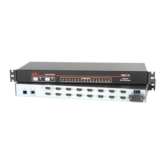
RSM-16 Models
RSM-8 Models
WTI Part No. 14023
TSM Series
Serial Console Servers
RSM Series
Remote Site Managers
Remote Site Managers with Power Control
RSM-xRy Series
RSM-16R16 Models
RSM-8R8 Models
RSM-2R4 Models
Rev. O
Advertisement
Table of Contents


Need help?
Do you have a question about the TSM Series and is the answer not in the manual?
Questions and answers