Table of Contents
Advertisement
A / V Receiver
DTR-7
DTR-6
Instruction Manual
DIMMER
STANDBY/ON
SANDBY MULTI SOURCE
POWER
ON
OFF
A SPEAKERS B
DISPLAY
DIRECT
STEREO
PHONES
MUL
TI CH
INPUT
DVD
VIDEO-1
VIDEO-2
VIDEO-3
VIDEO-4
Thank you for purchasing the Integra Audio Video
Control Receiver.
Please read this manual thoroughly before making
connections and turning on the power.
Following the instructions in this manual will enable
you to obtain optimum performance and listening
enjoyment from your new Audio Video Control
Receiver.
Please retain this manual for future reference.
MASTER VOLUME
FM MUTE/
CHARACTER/
SP/SYS
AUDIO
BASS/
MODE
DOWN
TUNING
UP
MEMORY
SETUP
ADJUSTMENT
TREBLE
MODE
PRESET/MODE ADJ
PUSH TO ENTER
LISTENING MODE
REC OUT /
DIGITAL/
DSP
MULTI SOURCE
ANALOG
CH LEVEL
/DTS
THX
SURROUND
MODE
VIDEO
4
(MONO)
TAPE
FM
AM
PHONO
C D
S VIDEO
VIDEO
L
AUDIO
R(MONO)
DTR -
7
by
Contents
Before using
Important Safeguards ........................................ 2
Precautions ........................................................ 3
Features ............................................................. 4
Supplied accessories ......................................... 4
Before operating this unit ................................. 5
Preparation
Audio equipment connections .......................... 6
Video equipment connections ........................... 8
with 5.1-channel output .................................. 9
Connecting speakers ....................................... 10
Connecting power amplifiers .......................... 12
Connecting an equalizer .................................. 13
Connecting the power ..................................... 13
Making antenna connections .......................... 14
Operation
Using the on-screen display ............................ 16
Setting the speaker configuration ................... 18
Setting the speaker distance ............................ 20
Setting the speaker Level ................................ 21
Playing a digital source ................................... 23
Presetting FM/AM radio stations .................... 24
Selecting an input source ................................ 26
Selecting a preset station ................................. 32
Playing a multichannel input source ............... 33
Using the Listening Modes ............................. 34
Setting the listening mode parameters .................... 38
to each audio input source .............................. 40
and preset radio station ................................... 41
while listening to it ......................................... 42
Other setup operations .................................... 43
Recording a source .......................................... 44
Using Multi-Room Remote System ................ 46
The initial settings ........................................... 48
Appendix
Using the remote controller ............................ 49
other devices into the RC-392M ..................... 52
Using a Macro function .................................. 54
Troubleshooting guide .................................... 58
Specifications .................................................. 60
Control positions and names ........................... 62
Advertisement
Table of Contents

Related Manuals for Integra DTR-7


Summary of Contents for Integra DTR-7
-
Page 1: Table Of Contents
VIDEO-2 VIDEO-3 VIDEO-4 TAPE PHONO Thank you for purchasing the Integra Audio Video Control Receiver. Please read this manual thoroughly before making connections and turning on the power. Following the instructions in this manual will enable you to obtain optimum performance and listening enjoyment from your new Audio Video Control Receiver. -
Page 2: Important Safeguards
WARNING: TO REDUCE THE RISK OF FIRE OR ELECTRIC SHOCK, DO NOT EXPOSE THIS APPLIANCE TO RAIN OR MOISTURE. CAUTION: TO REDUCE THE RISK OF ELECTRIC SHOCK, DO NOT REMOVE COVER (OR BACK). NO USER-SERVICEABLE PARTS INSIDE. REFER SERVICING TO QUALIFIED SERVICE PERSONNEL. -
Page 3: Precautions
Precautions 1. Warranty Claim You can find the serial number on the rear panel of this unit. In case of warranty claim, please report this number. 2. Recording Copyright Recording of copyrighted material for other than personal use is il- legal without permission of the copyright holder. -
Page 4: Features
Linear PCM 96 kHz/24-bit D/A converter 5.1 multichannel inputs 4 assignable digital inputs (2-coaxial, 2-optical) Optical digital output (DTR-7 only) Onscreen display Main-in jacks for front left & right channels (DTR-7 only) Pre outs for all channels... -
Page 5: Before Operating This Unit
Before operating this unit Remote control sensor STANDBY indicator 30˚ 30˚ Installing the remote controller batteries 1. Remove the battery compartment cover by pressing the tab and lifting up the cover. 2. Insert two AA (R6- or UM-3)-size batteries into the battery compartment. -
Page 6: Audio Equipment Connections
OUTPUT Turntable Audio connection cable L (Left) R (Right) Improper Connection Insert completely :Signal Flow MD recorder / DAT etc... DTR-7 / DTR-6 SURROUND SPEAKERS FRONT SPEAKERS A ANTENNA VIDEO-1 CENTER SPEAKER VIDEO-2 CAUTION: SPEAKER IMPEDANCE 6 OHMS MIN. / SPEAKER... - Page 7 They both offer the same functionality. • You can use the remote controller for the DTR-7/DTR-6 to control an Onkyo/Integra DVD player or MD recorder that is not connected via an z cable. When you control such a DVD player or MD recorder, point the remote controller toward the sensor area of the DVD player or MD recorder.
-
Page 8: Video Equipment Connections
• Please refer to the instruction manual of each component when making any connections. Audio connection cable L (Left) R (Right) Video Disc Player AUDIO DIGITAL INPUT COAXIAL COAXIAL OPTICAL OPTICAL OPTICAL DIGITAL OUTPUT DTR-7 only DTR-7/DTR-6 FM MUTE/ CHARACTER/ DIMMER MODE DOWN TUNING MEMORY STANDBY/ON ANDBY TI SOURCE POWER... -
Page 9: Connecting Equipment With 5.1-Channel Output
WOOFER OPTICAL CENTER VIDEO-2 SURROUND OPTICAL VIDEO-3 FRONT OPTICAL WOOFER FRONT SPEAKERS B DIGITAL OUTPUT CENTER AV RECEIVER MODEL NO. DTR-7 SURROUND (REC) MONITOR MULTI CHANNEL INPUT TAPE MULTI SOURCE (PLAY) VIDEO PHONO S VIDEO OSD SELECTOR LOCAL REMOTE REMOTE... -
Page 10: Connecting Speakers
Connecting speakers The DTR-7/6 allows you to connect two speaker systems. Before connecting the speakers, place them correctly by consulting the instruction manuals that came with your speakers. For surround playback (see “Using the listening modes” on page 34), the configuration and placement of your speakers are very important. - Page 11 S VIDEO OSD SELECTOR LOCAL REMOTE REMOTE CONTROL DTR-7 / DTR-6 • When you use only one speaker or wish to listen to monaural (mono) sound, a single speaker should never be connected in parallel to both the right and left chan- terminals neously.
-
Page 12: Connecting Power Amplifiers
REMOTE CONTROL Connecting power amplifiers Using auxiliary power amplifiers allows you to listen at louder vol- umes than with the DTR-7/DTR-6 alone. If power amplifiers are VIDEO-1 used, connect each speaker to the corresponding power amplifier. VIDEO-2 When using speakers connected through external power amplifiers, VIDEO-3 turn OFF the SPEAKERS A. -
Page 13: Connecting An Equalizer
Notes: • Do not use any power cable other than the included cable. The included cable is designed for use only with the DTR-7/ DTR-6. Do not use it for any other device. • Do not connect or disconnect the outlet plug from the DTR-7/DTR-6 while the other end is plugged into the wall AC outlet. -
Page 14: Making Antenna Connections
Making antenna connections Slit C Directional linkage type splitter To receiver Insert into the hole. Connecting the antenna cable to the 75/300 ohm antenna adapter. (The antenna adapter must be Outdoor Indoor separately ordered.) antenna antenna Connecting the 300 ohm ribbon wire: 300 ohms Loosen the screws and wrap the wire around these screws. - Page 15 Making antenna connections Remove the insulation at the end of the cable, then fully insert the stripped end of the cable. ANTENNA Outdoor antenna ANTENNA Connecting the included antennas Connecting the FM indoor antenna: The FM indoor antenna is for indoor use only. Extend the antenna and move it in various directions until the clearest signal is received.
-
Page 16: Using The On-Screen Display
Using the on-screen display ** Screen Setup ** Background Color = Green 1 Superimpose Mode = Normal Immediate Display = ON Character Position Using the OSD (on-screen display) function lets you display each screen on your TV so that you can perform various settings using only the remote controller. - Page 17 Using the on-screen display OSD screens *** Menu *** Input Selector Rec Selector Listening Mode Setup Speaker Setup Screen Setup Input Selector screen (page 27,32) ** Input Selector ** Input = DVD OPTICAL 1 Digital Input Setup Video Assign Setup IntelliVolume Setup Listening Dolby Mode= Pro Logic...
-
Page 18: Setting The Speaker Configuration
1. Press the SP/SYS SETUP button. “Config Setup?” appears. Then Press the SMART SCAN CON- TROLLER. 2. For the DTR-6, go to the next step. For the DTR-7, “All Ch For THX” appears. Set “Yes” or “No.” Yes: No : Press the SMART SCAN CONTROLLER. - Page 19 3. Select “Config Setup” and then press the right edge of the ENTER/Cursor button. 4. For the DTR-6, go to the next step. For the DTR-7, the display shows “All Channel For THX Speakers.” Select “Yes” and then press the center of the ENTER/Cursor button.
-
Page 20: Setting The Speaker Distance
Setting the speaker distance SP/SYS SPEAKERS SETUP PRESET/MODE ADJ PUSH TO ENTER 2 ~ 7 PRESET/MODE ADJ SPEAKERS PUSH TO ENTER PRESET/MODE ADJ PUSH TO ENTER PRESET/MODE ADJ PUSH TO ENTER * Distance Setup * Left =3.6m/12ft Center =3.6m/12ft Right =3.6m/12ft (R-Sur =2.1m/ 7ft) -
Page 21: Setting The Speaker Level
Setting the speaker Level SP/SYS SETUP SPEAKERS PRESET/MODE ADJ PUSH TO ENTER PRESET/MODE ADJ SPEAKERS PCM DIGITAL PUSH TO ENTER Center PRESET/MODE ADJ Right R-Sur PUSH TO ENTER L-Sur * Level Setup * Left = +1dB Center (Right Using the test tone to adjust the speaker output levels 1. - Page 22 SPEAKERS PUSH TO ENTER Setting the bass peak level (Bass Peak Level Manager* DTR-7 only) To prevent damage to your subwoofer, you can set the bass peak level the subwoofer can reproduce. If your system does not include any subwoofer, this will set the bass peak level your Front speakers can reproduce.
-
Page 23: Playing A Digital Source
Setting the Speaker level * Bass Peak Setup * Bass Peak Level Limiter = Yes Peak Level =+18dB Starting The Test Tone * Bass Peak Setup * 1.Turn Volume Up. 2.When Sound Distorts. 3.Press ENTER. Level Playing a digital source (Digital Input Setup) DIGITAL/ SPEAKERS ANALOG... -
Page 24: Presetting Fm/Am Radio Stations
Presetting FM/AM radio stations STANDBY/ON ANDBY TI SOURCE POWER A SPEAKERS B TI CH INPUT PHONES DOWN TUNING SPEAKERS FM MUTE/ MODE DISPLAY TUNING UP/DOWN FM MUTE/MODE CHARACTER/MEMORY FM MUTE/ CHARACTER/ SP/SYS DIMMER MODE DOWN TUNING MEMORY SETUP SMART SCAN CONTROLLER LISTENING MODE REC OUT /... - Page 25 Presetting FM/AM radio stations SPEAKERS CHARACTER/ MEMORY SPEAKERS PRESET/MODE ADJ MEMORY PUSH TO ENTER PRESET/MODE ADJ SPEAKERS PUSH TO ENTER PRESET/MODE ADJ PUSH TO ENTER CHARACTER/ MEMORY SPEAKERS PRESET/MODE ADJ SPEAKERS PUSH TO ENTER PRESET/MODE ADJ PUSH TO ENTER Programming radio stations TUNED 1.
-
Page 26: Selecting An Input Source
Selecting an input source . Make sure that the SPEAKERS A indicator is lit on the display. If it is not lit, press the SPEAKERS A button. STANDBY/ON ANDBY TI SOURCE POWER A SPEAKERS B TI CH INPUT PHONES 4 PHONES . - Page 27 1 This button allows you to set the sleep timer. (See page 31.) 2 Press this button to set the mode in which you can operate the DTR-7/6. 3 Use this button to change the brightness of the display (normal or dim).
- Page 28 Selecting an input source VIDEO-1 VIDEO-2 VIDEO-3 VIDEO-4 DIGITAL/ SPEAKERS ANALOG PRESET/MODE ADJ SPEAKERS PUSH TO ENTER PRESET/MODE ADJ SPEAKERS PUSH TO ENTER PRESET/MODE ADJ PUSH TO ENTER Setting the input signal format The input signal format defaults to “Automatic.” Although you can TAPE PHONO use this default setting normally, you may change it depending on...
- Page 29 In such cases, try playing the source in the “DTS” mode. 4. The DTS indicator on the DTR-7/DTR-6 lights up while it plays the DTS source. When playback concludes and the DTS signal transmission stops, the DTR-7/DTR-6 remains in DTS mode and the DTS indicator remains lit.
- Page 30 • “Input signal format” returns to “Listening mode” within 3 seconds. Selecting the speaker system The DTR-7/DTR-6 can connect to two speaker systems. You can switch between the two speaker systems by using the SPEAKERS A and B buttons. Selecting Speaker system A (SPEAKERS A indicator appears.)
- Page 31 Falling asleep with music (Sleep function, remote controller only) You can turn off the power to the DTR-7/DTR-6 automatically after a specified time period. 1. Press the MODE AUDIO button. 2. Press the SLEEP button.
-
Page 32: Selecting A Preset Station
Selecting a preset station STANDBY/ON ANDBY TI SOURCE POWER A SPEAKERS B PHONES ** Input Selector ** Input = TUNER Present No. Video Assign Setup IntelliVolume Setup Listening Mode= Orchestra * Preset Station * Preset No. = 3 1:---- 2:---- 3:87.60 4:---- 5:----... -
Page 33: Playing A Multichannel Input Source
Playing a multichannel input source Remote controller MULTI CH INPUT ** Multi Ch Input Level Setup Left Center = +5dB Right Left Sur Left Sur Subwoofer =+10dB Setting the MULTI CHANNEL INPUT To play back an input source you connected with the MULTI CHANNEL INPUT connectors, you must set the output level of each speaker. -
Page 34: Using The Listening Modes
Suitable for musical film soundtracks, where importance is placed on the music, environmental sound, and front image. Integra’s listening modes MONO MOVIE (DTR-7 only) : This mode is suitable for play back monaural recordings such as old movie soundtracks. The center channel delivers unprocessed original sound, whereas the other channels delivers processed center-channel sound with ap- propriate reverberation. - Page 35 Using the listening modes . Use the LISTENING MODE buttons to select the desired listening mode and then start play- ing the selected source. DIMMER STANDBY/ON ANDBY TI SOURCE POWER A SPEAKERS B DISPLAY TI CH INPUT PHONES . Press one of the INPUT SELECTOR buttons to select the desired sound source.
- Page 36 DIRECT : Press this button if you wish to enjoy pure direct STEREO : Press this button to listen to a normal stereo audio. 5CH STEREO(DTR-6) : Press this button to play 5-ch stereo THX(DTR-7) : Press this button when THX speakers are used. Notes: 5CH STEREO •...
- Page 37 Using the listening modes Input sources and listening modes The available listening modes vary depending on the input source. The following table shows each input source and the available listening modes. *Available for DTR-6. Input source analog/PCM Listening mode Stereo (3 Stereo) Dolby Pro Logic THX Cinema Action...
-
Page 38: Setting The Listening Mode Parameters
Setting the listening mode parameters LISTENING MODE DIRECT STEREO /DTS SURROUND AUDIO ADJUSTMENT SPEAKERS PRESET/MODE ADJ PRESET/MODE ADJ PUSH TO ENTER PUSH TO ENTER ** Listening Mode Listening Mode=Mono Movie Front Effect Reflect Level = Reverb Level Room Size Default Parameter Listening mode Stereo(3 Stereo) - Page 39 You can adjust the strength of direct sound reflection, depending on the playback source material, your audio room conditions, and so • Reverb Level (DTR-7 only) Set a value between -5 and +5 dB, in units of 1 dB. Adjust the depth of acoustic reverberation, depending on the play- back source material, your audio room conditions, and so on.
-
Page 40: Assigning A Video Source To Each Audio Input Source
Assigning a video source to each audio input source VIDEO-1 VIDEO-2 VIDEO-3 VIDEO-4 SP/SYS SETUP SPEAKERS PRESET/MODE ADJ PUSH TO ENTER PRESET/MODE ADJ SPEAKERS PUSH TO ENTER PRESET/MODE ADJ PUSH TO ENTER * Video Assign Setup * :---- PHONO :---- :---- :---- TAPE... -
Page 41: Giving A Name To Each Input Source And Preset Radio Station
Giving a name to each input source and preset radio station VIDEO-1 VIDEO-2 VIDEO-3 VIDEO-4 TAPE CHARACTER/ MEMORY SPEAKERS PCM DIGITAL PRESET/MODE ADJ SPEAKERS PUSH TO ENTER PRESET/MODE ADJ SPEAKERS PUSH TO ENTER PRESET/MODE ADJ SPEAKERS PUSH TO ENTER SPEAKERS 2 ~ 5 Giving a name to each input source You can give a desired name to each input source (DVD, CD,... -
Page 42: Adjusting The Output Level Of Each Speaker While Listening To It
Adjusting the output level of each speaker while listening to it CH LEVEL SPEAKERS PRESET/MODE ADJ PUSH TO ENTER PRESET/MODE ADJ PUSH TO ENTER Fine-tuning the output level of each speaker You can fine-tune the output level of each speaker according to your taste. -
Page 43: Other Setup Operations
Other setup operations SP/SYS SETUP SPEAKERS PRESET/MODE ADJ PUSH TO ENTER PRESET/MODE ADJ SPEAKERS PUSH TO ENTER SPEAKERS PRESET/MODE ADJ PUSH TO ENTER VIDEO-1 VIDEO-2 VIDEO-3 VIDEO-4 TAPE SP/SYS SETUP SPEAKERS PRESET/MODE ADJ PUSH TO ENTER PRESET/MODE ADJ PUSH TO ENTER SPEAKERS PRESET/MODE ADJ PUSH TO ENTER... -
Page 44: Recording A Source
2. Press the REC OUT button. REC OUT Notes: • For DTR-7, The digital input signals assigned to the input source you • You cannot select the source connected to the MULTI CHANNEL IN- STEREO 4. Start recording on the recorder connected to the TAPE, Notes: •... - Page 45 Recording a source HONO SP/SYS SETUP SPEAKERS PRESET/MODE ADJ PUSH TO ENTER PRESET/MODE ADJ SPEAKERS PUSH TO ENTER PRESET/MODE ADJ PUSH TO ENTER REC OUT PRESET/MODE ADJ SPEAKERS REC OUT PUSH TO ENTER ** Rec Selector ** •Picture VIDEO =DVD •Sound TAPE =DVD...
-
Page 46: Using Multi-Room Remote System
If you connect Onkyo Multi-room Remote System components as shown in the figure below, you can control the components from a sub- room as well as from the room where the DTR-7/DTR-6 is located. The Multi-Room Remote System allows remote operation when the A/V system is mounted in a cabinet or rack. - Page 47 INPUT VIDEO-1 VIDEO-2 VIDEO-3 VIDEO-4 TAPE REC OUT/MULTI SOURCE 1. POWER ON 2. Input Selector When the system is mounted in a rack: DTR-7/DTR-6 DIGITAL INPUT SURROUND SPEAKERS FRONT SPEAKERS A AMP IN FRONT COAXIAL ANTENNA VIDEO-1 PRE OUT FRONT...
-
Page 48: The Initial Settings
The initial settings The following table shows the factory-set default parameter values. Use it as a reference when you change these parameter values as needed, although they are usable in many cases. Initial settings Config Setup All Ch For THX When set to “No”... -
Page 49: Using The Remote Controller
Using the remote controller Overview When you use a remote controller, typically you press one of the MODE buttons that corresponds to the device you wish to control, then press the operation buttons. For example, if you wish to control the receiver from a remote controller, first press the MODE AUDIO button, then press an appropriate operation button. - Page 50 Using the remote controller Controlling an Onkyo/Integra CD player Note: First connect an Onkyo/Integra CD player using the zconnection. (See page 7.) 1. Press the MODE CD button. 2. Press the desired CD operation button. TRACK MODE CD DISC EJECT r...
- Page 51 ENT button MUTING Controlling an Onkyo/Integra tape deck MODE Note: AUDIO/TAPE First connect an Onkyo/Integra tape deck using the zconnection. (See page 7.) 1. Press the MODE AUDIO/TAPE button. 2. Press the desired tape deck operation button. TAPE REC o...
-
Page 52: Programming The Remote Controller Codes Of Other Devices Into The Rc-392M
RC-392M. You may pro- gram other remote controller codes into these buttons. If you wish to restore the Onkyo/Integra preset codes after you pro- gram new codes, erase the new codes. (See page 53.) - Page 53 Programming the remote controller codes of other devices into the RC-392M See page 57 for information on how to erase the learned codes from all buttons. Erasing a learned code SEND/LEARN indicator You can erase a learned code. You cannot erase preset codes. •...
-
Page 54: Using A Macro Function
Using a Macro function What is a Macro function? A Macro function enables you to program a series of button operations into a single button on the remote controller. For example, you need to follow the steps below to play a CD player connected to the receiver without using the Macro function: 1: Press the MODE AUDIO button. - Page 55 Using a Macro function 1, 3 Tip: The codes programmed into a MACRO button will be transmitted with an interval of 0.5 seconds. However, some devices may not be able to complete one operation in 0.5 seconds and may miss the next code.
- Page 56 Using a Macro function 1, 2 Erasing a learned remote controller button operation from the MACRO MODE buttons 1. Press and hold down the corresponding MODE button and press the MACRO MODE button, then release the buttons. When you press the MODE button, the SEND/LEARN indica- tor lights up.
- Page 57 Using a Macro function Erasing all codes and operations programmed in the buttons This procedure will erase all remote controller codes for the other devices and all macro operations that have been programmed in the RC-392M (see pages 52, 54 and 55). 1.
-
Page 58: Troubleshooting Guide
Troubleshooting guide If a problem occurs while you are using the remote controller, first try to operate the front panel controls on the main unit to make sure that it is not due to a malfunction (or worn out batteries) in the remote controller. Trouble POWER Power shut off immedi-... - Page 59 Troubleshooting guide Trouble FM/AM TUNED and STEREO • Station is too strong. indicators light • Multiple reflection of the radio waves because sound is distorted and of tall buildings or mountains. stereo separation is bad. TUNED and STEREO • Station is too weak. indicators flicker and •...
-
Page 60: Specifications
Specifications DTR-7 AMPLIFIER SECTION Continuous Average Power output (FTC) All channels: 105 watts per channel min. RMS at 8 ohms, 2 channels driven from 20 Hz to 20 kHz with no more than 0.08% total harmonic distortion. 135 watts min. RMS at 6 ohms, 2 channels driven from 1 kHz with no more than 0.1% total harmonic dis-... - Page 61 Specifications DTR-7 TUNER SECTION Tuning Range: 87.5 - 108.0 MHz (50 kHz steps) Usable Sensitivity Mono: 11.2 dBf, 1.0 V (75 ohms IHF) Stereo: 17.2 dBf, 2.0 V (75 ohms IHF) 50 dB Quieting Sensitivity Mono: 17.2 dBf, 2.0 V (75 ohms) Stereo: 37.2 dBf, 20 V (75 ohms)
-
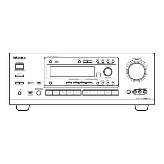
Page 62: Control Positions And Names
Control positions and names The illustration shows the front panel of the DTR-7 model. The ap- pearance of the front panel varies depending on the model you pur- chased. STANDBY/ON ANDBY TI SOURCE POWER A SPEAKERS B PHONES SPEAKERS REC OUT... - Page 63 Control positions and names Remote controller Using the remote controller, you can control a CD player or cas- sette tape deck connected to the connector of the DTR-7/6. (See page 7 for more information.) 1. SEND/LEARN indicator [49, 52, 53] 2.
- Page 64 ONKYO U.S.A. CORPORATION SN 29342732 Printed in Japan 200 Williams Drive, Ramesy, N.J. 07446, U.S.A. Tel: 201-825-7950 Fax: 201-825-8150 E-mail: integra@onkyousa.com D9907-1...
Need help?
Do you have a question about the DTR-7 and is the answer not in the manual?
Questions and answers