Table of Contents
Advertisement
Quick Links
Advertisement
Table of Contents

Subscribe to Our Youtube Channel
Related Manuals for Infranor SMT-BD2


Summary of Contents for Infranor SMT-BD2
- Page 1 SMT-BD2 DIGITAL SERVO DRIVE FOR SINUSOIDAL BRUSHLESS AC MOTORS SMT-BD2...
- Page 2 SMT-BD2 SMT-BD2...
- Page 3 INFRANOR does not assume any responsibility for any physical or material damage due to improper handling or wrong descriptions of the ordered items.
- Page 4 SMT-BD2 SMT-BD2...
-
Page 5: Table Of Contents
SMT-BD2 Contents CONTENTS............................. 5 CHAPTER 1 - GENERAL DESCRIPTION ..................... 7 1 - INTRODUCTION..........................7 2 - GENERAL DESCRIPTION......................7 3 - REFERENCE TO THE STANDARDS ..................... 8 4 - REFERENCE TO OTHER DOCUMENTS..................8 CHAPTER 2 – SPECIFICATIONS......................9 1 - TECHNICAL SPECIFICATIONS ..................... - Page 6 SMT-BD2 1. 3 - Hall Effect Sensors configuration................... 35 1. 4 - Motor thermal sensor configuration ..................35 1.5 - Current loops adjustments...................... 36 2 - PUTTING INTO OPERATION ....................... 38 3 - AMPLIFIER COMMISSIONING AND ADJUSTMENT ..............38 3.1 - Amplifier setup ........................38 3.2 - Motor Hall Effect Sensors adjustment ..................
-
Page 7: Chapter 1 - General Description
The speed or torque/force input command is a +/-10 V analog signal voltage. The SMT-BD2 digital servo drive is 220 VAC or 400 VAC main operated. The SMT-BD2 plug-in system with 400 VAC power supply is available as a multiaxis version that can receive up to three axes in a standard 19" rack including the power supply. -
Page 8: Reference To The Standards
3 - REFERENCE TO THE STANDARDS The 220 VAC version of the SMT-BD2 amplifiers operating in the BF rack, which is equipped with the mains filter BF-35 or 70, has been approved for its conformity with the Electromagnetic Compatibility standards: EN 55011, Group 1, Class A regarding the conducted and radiated radioelectric disturbances, CEI 801 - 2 - 3 - 4 regarding the immunity. -
Page 9: Chapter 2 - Specifications
* Maximum ambient temperature = + 40° C, fan 1 = 56 l/s, fan 2 = 90 l/s. Note: The SMT-BD2-X/Xr amplifier types are equipped with an additional heatsink in order to improve the heat dissipation and increase their rated current. The width of these amplifier types is then 18 TE instead of 12 TE. -
Page 10: Current Ratings For The 400 Vac Amplifier Version
U rated Imax (Arms) (Arms) of the amplifier (Vrms) WITHOUT FAN TYPE FAN* SMT-BD2 - 400/15 15.5 SMT-BD2 - 400/30 SMT-BD2 - 400/45 SMT-BD2 - 400/60 not used Authorized output currents for continuous current mode operation (I t protection in limiting mode) Max. -
Page 11: Other Specifications
SMT-BD2 1.3 - O THER SPECIFICATIONS PWM switching frequency 10 KHz Current regulator (PI) Adjusted to motor Current loop bandwidth Cut-off frequency for 45° phase shift > 1 KHz Internal current limitation Maximum current range : 20 % to 100 % of Imax... - Page 12 SMT-BD2 Encoder input Selectable by jumpers : Quadrature TTL A & B with Z marker pulse RS 422 line receiver maximum pulses frequency: 1 MHz Resolution: 500 to 10 ppr (as from EPROM version 7.1C) Incremental Sin/Cos encoder Heidenhain 1 Vcc Sin/Cos type or compatible...
-
Page 13: Block Diagram
Serial parameters link The PR8 and PR10 connectors are not accessible for direct wiring; they are plugged on the BM20A single-axis rack or on the multiaxes BF rack according to the SMT-BD2 amplifier housing (see chapter Chapter 2 - Specifications... -
Page 14: Main Protections
SMT-BD2 3 - MAIN PROTECTIONS 3.1-D ISPLAYED PROTECTIONS PROTECTION ERROR DISPLAY LED* Amplifier rated current overload . blinking display = I t warning threshold is reached (Idyn output) . continuous display = I t fault (amplifier inhibited in fusing mode) -
Page 15: Fuse Protection
3.2.2 - Fuse protection for the 400 VAC amplifier version F2 : Control of the average DC current of the logic board supply (see Hardware adjustments in chapter 5, § AMPLIFIER TYPE Logic SMT-BD2 - 400/15 SMT-BD2 - 400/30 SMT-BD2 - 400/45 SMT-BD2 - 400/60 Chapter 2 - Specifications... -
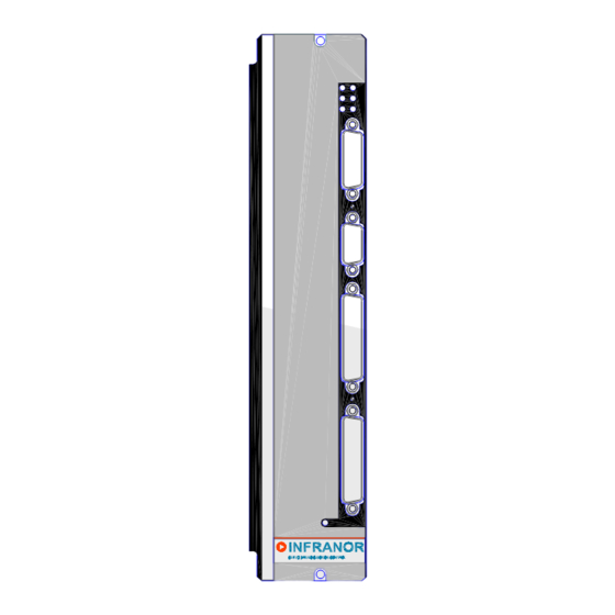
Page 16: Chapter 3 - Inputs - Outputs
SMT-BD2 Chapter 3 - Inputs - Outputs 1 - CONNECTORS LOCATION 1.1 - RACK CONNECTORS For the 400 VAC amplifier version, see BF-400 RACK manual. For the 220 VAC amplifier version, see SMTB.M 20 A SINGLE-AXIS RACK manual or BF RACK manual. -
Page 17: X1 Encoder Feedback Connector (Subd 15 Points Female )
SMT-BD2 3 - X1 ENCODER FEEDBACK CONNECTOR (Sub D 15 points female) 3.1 – X1 CONNECTOR FOR INCREMENTAL ENCODER CONFIGURATION The "TTL incremental encoder" configuration is selected according to the following COM and COD jumpers setting (see chapter 5, section 1: Hardware adjustments). -
Page 18: X1 Connector For Ttl Incremental Encoder & Hes Configuration
SMT-BD2 3.2 – X1 & HES CONNECTOR FOR INCREMENTAL ENCODER CONFIGURATION The “ TTL incremental encoder & HES” configuration is selected according to the following COM and COD jumpers setting (see chapter 5, section 1: Hardware adjustments). 60° HES type 120°... -
Page 19: X1 Connector For Absolute Single Turn Sin/Cos Encoder Configuration
SMT-BD2 3.3 – X1 CONNECTOR FOR ABSOLUTE SINGLE TURN OS ENCODER CONFIGURATION The “ Absolute single turn Sin/Cos encoder ” configuration (Heidenhain ERN 1085 or compatible) is selected according to the following COM and COD jumpers setting (see chapter 5, section 1: Hardware adjustments). -
Page 20: X1 Connector For Other Sin/Cos Encoder Configurations
SMT-BD2 3.4 - X1 CONNECTOR FOR OTHER SIN COS ENCODER CONFIGURATIONS 3.4.1 – X1 CONNECTOR FOR INCREMENTAL SIN/COS ENCODER CONFIGURATION The “ Incremental Sin/Cos encoder ” configuration (Heidenhain 1Vcc Sin/Cos encoder or compatible) is selected according to the following COM and COD jumpers setting (see chapter 5, section 1: Hardware adjustments). -
Page 21: X4 Command Connector (Subd 25 Points Male )
SMT-BD2 4 - X4 COMMAND CONNECTOR (Sub D 25 points male) Function I / O REMARKS Limit switch + Optoisolated input (I/O jumper open), positive logic (5V to 24V) Limit switch - Optoisolated input (I/O jumper open), positive logic (5V to 24V) -
Page 22: Specification Of The Analog Inputs / Outputs
SMT-BD2 4.1 - S PECIFICATION OF THE ANALOG INPUTS OUTPUTS 22 nF SMT-BD2 20 KΩ 10 KΩ 10 KΩ X4-17 (CV+) X4-16 (CV-) 10 KΩ 10 KΩ 20 KΩ 10 nF 22 nF 10 nF 22 nF 20 KΩ 10 KΩ... -
Page 23: Specification Of The Logic Inputs / Outputs
X4-23, 24, 25 I/O jumper open When the I/O jumper is open, the 0 V of the optoisolated inputs (X4 pins 23,24,25) is not connected to the 0 V of the SMT-BD2 amplifier module (X4, pin 12). SMT-BD2 4,1 KΩ... -
Page 24: X2 Position Output Connector (Subd 25 Points Female )
SMT-BD2 5 - X2 POSITION OUTPUT CONNECTOR (Sub D 25 points female) FUNCTION I / O REMARKS Marker Z/ Differential output of the encoder marker pulse (5 V, 20 mA max.) Marker Z Differential output of the encoder marker pulse Channel A/ Differential output of the encoder channel A/ (5 V, 20 mA max.) -
Page 25: Chapter 4 - Connections
I/O jumper open The I/O jumper must be open for getting the X4 connector I/Os optoisolation : the I/O 0 V (X4, pins 23, 24, 25) is disconnected from the 0 V of the SMT-BD2 amplifier module. Chapter 4 - Connections... - Page 26 I/O jumper open The I/O jumper must be open for getting the X4 connector I/Os optoisolation : the I/O 0 V (X4, pins 23, 24, 25) is disconnected from the 0 V of the SMT-BD2 amplifier module. Chapter 4 – Connections...
-
Page 27: Rs-232 Serial Link Connection
Pont I/O fermé Le pont des I/O doit être fermé pour que le 0 V des E/S (X4, pins 23, 24, 25) soit connecté au 0 V du module variateur SMT-BD2. 1.3 – CONNEXION DE LA LIAISON SERIE RS-232 Reprise de blindage sur 360°... -
Page 28: Wiring (According To Cei 801 And En 55011 Standards)
SMT-BD2 2 - WIRING (according to CEI 801 and EN 55011 standards) 2.1 - GND WIRING AND GROUNDING The reference potential is the earth (ground). Motors and sensors (encoder + HES) are grounded via their housing. If a potential reference is existing, like a main chassis or a cabinet, with a low impedance between the various elements, it should be used to connect ALL references to it and also connect this reference to the earth (ground). -
Page 29: 360° Shield On The Connectors
SMT-BD2 3 - 360° SHIELD ON THE CONNECTORS RULE : The shield must never be interrupted or corrupted over the whole cable length. Self-sticking copper ribbon if necessary, for increasing the shield diameter in order to get it correctly tightened... -
Page 30: Chapter 5 - Adjustable Functions
SMT-BD2 Chapter 5 - Adjustable functions 1 - HARDWARE ADJUSTMENTS All the hardware adjustments of the SMT-BD2 amplifier module are presented on the following diagrams. Current loops (power board) +5 V supply RS-422 (option) Inputs 0 V Serial link selection:... - Page 31 SMT-BD2 A and B OPEN: with auxiliary supply A and B CLOSED: without auxiliary supply Power board adjustment for amplifier types 220/70 A and 220/100 A Chapter 5 - Adjustable functions...
- Page 32 SMT-BM 20 A single-axis rack: Braking resistor jumper closed. BF-rack: Braking resistor jumper open. NOTE: This braking resistor system selection is only available on « w » referenced amplifiers. Braking system selection on SMT-BD2-220/04w to 220/60w Chapter 5 – Adjustable functions...
-
Page 33: Adjustable Parameters
SMT-BD2 2 – ADJUSTABLE PARAMETERS The SMT-BD2 serial link connector (X5) must be connected to the serial interface of a PC for the parameter setting operation. The Visual Drive Setup software, which is IBM-PC compatible with the WINDOWS® operating system, allows the clear display and easy modification of all amplifier parameters. -
Page 34: Chapter 6 - Commissioning
1 - CHECKING THE AMPLIFIER CONFIGURATION 1.1 - S TANDARD AMPLIFIER CONFIGURATION The standard SMT-BD2 amplifier configuration is given below. See chapter 5, section 1 "Hardware adjustments" for the jumpers location. Inputs 0 V reference jumper I/O is open (optoisolated inputs) -
Page 35: Hall Effect Sensors Configuration
SMT-BD2 1. 3 - H FFECT ENSORS CONFIGURATION If the motor is equipped with Hall Effect Sensors devices (HES), select the following COM jumpers setting according to the HES type (60° or 120°). 60° HES type 120° HES type If the motor is not equipped with Hall Effect Sensors devices, the following COM jumpers setting must be selected. -
Page 36: Current Loops Adjustments
SMT-BD2 1.5 - C URRENT LOOPS ADJUSTMENTS 1.5.1 - Current loops adjustments for the 400 VAC amplifier version Select the right current loops jumpers setting (B1, B2 or B3 position) according to motor and amplifier specifications. For the 400VAC version of the BL MAVILOR motor series, the current loops adjustments are made according to following selection table. - Page 37 SMT-BD2 1.5.2 - Current loops adjustments for the 220 VAC amplifier version Select the right current loops jumpers setting (B1, B2 or B3 position) according to motor and amplifier specifications. For the BL and MA MAVILOR motor series, the current loops adjustments are made according to following selection table.
-
Page 38: Putting Into Operation
Start the Visual Drive Setup software installation and follow the instructions. Turn on the SMT-BD2 amplifier and start the Visual Drive Setup software. If the message "No serial communication found" appears on the screen, click on OK and check following points... -
Page 39: Motor Hall Effect Sensors Adjustment
SMT-BD2 3.2 - M OTOR FFECT ENSORS ADJUSTMENT If the motor is using Hall Effect Sensors, check that the COM jumpers setting is correct according to the motor HES type (60° or 120°). Check that the ENABLE input is disabled and the amplifier turned on. -
Page 40: Amplifier Parameter Setting
SMT-BD2 3.4 - A MPLIFIER PARAMETER SETTING Select Software control mode and switch on the Off position. Select the motor to be used in the Motor list and check the Motor encoder resolution value, the Speed limit and the Current limits according to the motor and amplifier specifications. -
Page 41: Saving Of The Amplifier Parameters
SMT-BD2 Move the shaft with a low digital speed reference value up to a maintaining position (far enough from the axis limit switches) where a free movement over 1 revolution, or 1 pole pitch for linear motors, is not dangerous for operator and machine. -
Page 42: Parameters Adjustment To A Linear Motor
SMT-BD2 3.8 – P ARAMETERS ADJUSTMENT TO A LINEAR MOTOR The Motor encoder resolution parameter is calculated as described below: Motor magnets Pole pitch Motor pole pitch (mm) Motor encoder resolution = 1000 x Encoder signal pitch (µm) 1 encoder signal pitch = 4 counting increments... -
Page 43: Chapter 7 - Fault Finding
SMT-BD2 Chapter 7 – Fault finding 1 - SYSTEM FAULT If the red SYS led is lit when the amplifier is on, the logic board is off duty. Check that the EPROM firmware memory is correctly plugged on the amplifier. -
Page 44: Eeprom" Fault
SMT-BD2 2.2 - "EEPROM" FAULT Check for the presence of the EEPROM and check its correct orientation and mounting. If the fault remains, the EEPROM is not correctly initialized (CHECKSUM error) or is not compatible with the amplifier software. In this case, if the EEPROM fault is reset and if then the Save parameters to EEPROM procedure is executed, the EEPROM is automatically reinitialized with the amplifier default parameters. -
Page 45: Encoder" Fault
SMT-BD2 Check that the Sin/Cos encoder commutation channels are correctly wired on the amplifier X1 connector. Check that the commutation signal jumpers COM are correctly set. Check for the correct Sin/Cos encoder supply voltage value. Check for the correct Sin/Cos encoder C channel and D channel signal amplitude value. -
Page 46: Counting" Fault
SMT-BD2 2.9 - "COUNTING" FAULT For the "TTL incermental encoder" configuration: Check that the encoder signal jumpers COD are correctly set (position B1). Check for the correct encoder supply voltage value Check for the correct encoder-amplifier-motor ground and shield connections with regard to the... -
Page 47: I 2 T" Fault
2.12 - "ADC" FAULT On SMT-BD2/b amplifiers equipped with the 16 bit ADC option, check for the correct orientation and the correct mounting of the 16 bit ADC component. Check that the input command wiring between controller and amplifier corresponds to the recommendations of chapter 4, and repeat the Offset compensation procedure. -
Page 48: Operating Problems
SMT-BD2 3 - OPERATING PROBLEMS 3.1 - M OTOR SUPPLIED BUT NO TORQUE Check the Maximum current and Rated current parameters. Check that the current limitation input (X4 pin 3) is not activated. Check that the amplifier is not operating in torque mode (X4 pin 4 active) with zero input command or with CV0 input activated. -
Page 49: Service And Maintenance
SMT-BD2 4 - SERVICE AND MAINTENANCE When exchanging an amplifier on a machine, proceed as follows: - Check that the new amplifier has the same hardware configuration as the old one, - Plug in the parameter EEPROM (or a copy of it) of the old amplifier on the new one, - Apply a zero speed input command and start the offset compensation procedure by means of the Offset button on the amplifier front panel. -
Page 50: Chapter 8 - Appendix
SMT-BD2 Chapter 8 - Appendix 1 - USE OF THE LIMIT SWITCHES & "CVO" INPUTS During the amplifier operation in speed mode (CI input inactive) the enabling of the CV0 input immediately stops the motor. The motor is decelerating according to the Accel/decel time parameter value. The motor is maintained at standstill while the CV0 input is activated. -
Page 51: I Tprotection
SMT-BD2 4 – I t PROTECTION 4.1 – C URRENT LIMITATION IN USING MODE When the amplifier RMS current (I t) reaches 85 % of the Rated current, the Idyn signal output is activated and the I t error display is blinking on the amplifier front panel. If the RMS current (I... -
Page 52: Current Limitation In Limiting Mode
For a given motor, the cogging can be easily evaluated by simply moving the motor manually when the amplifier is disabled. The Cogging compensation option available in the SMT-BD2 amplifier allows to cancel the motor cogging effects for specific applications where torque accuracy or force accuracy higher than 1 % are required. -
Page 53: Cogging Compensation Setup For Rotating Motors
SMT-BD2 5.2 – COGGING COMPENSATION SETUP FOR ROTATING MOTORS Cogging torque compensation is only valid on brushless rotating motors equipped with an encoder providing one marker pulse per motor revolution. Start the amplifier commissioning and adjustment as described in chapter Uncouple the motor from the load in order to avoid any external disturbance on the shaft during the cogging torque acquisition procedure. -
Page 54: Amplifier Types
When changing either the motor, the encoder or the amplifier, the cogging force acquisition procedure must be renewed. 6 - AMPLIFIER TYPES SMT-BD2 / _ _ - _ / _ _ / _ - T - _ _ Serial link : 1 = RS 232 / 2 = RS 422...
Need help?
Do you have a question about the SMT-BD2 and is the answer not in the manual?
Questions and answers