
Related Manuals for Infranor CD1-k


Summary of Contents for Infranor CD1-k
-
Page 1: Installation Guide
CD1-k – Installation Guide CD1-k Installation Guide CANopen amplifier ® INFRANOR CD1-k... - Page 2 This symbol indicates that INFRANOR devices must be eliminated by selective disposal and not with standard waste. INFRANOR does not assume any responsibility for any physical or material damage due to improper handling or wrong descriptions of the ordered items.
-
Page 3: Table Of Contents
1 - MAIN TECHNICAL DATA........................ 7 1.1 - CD1-k-230/I SINGLE-AXIS AMPLIFIER .................. 7 1.2 - CD1-K-400/I SINGLE-AXIS AMPLIFIER.................. 7 1.3 - COMMON SPECIFICATIONS TO THE CD1-k-230/I AND CD1-k-400/I AMPLIFIER TYPES. 8 2 - DIMENSIONS..........................11 2.1 - CD1-k-230/I AMPLIFIER…..................... 11 2.2 - CD1-k-400/1.8 TO 7.2 A AMPLIFIER.................. - Page 4 2.1 - GROUND CONNECTIONS AND GROUNDING..............29 2.2 - SHIELD CONNECTION OF THE CONNECTORS ..............30 2.3 - CONNECTION VUE OF CD1-K-400/30/45/70 AND 90 ............31 2.4 - MOTOR, RESOLVER AND ENCODER CABLES ..............31 2.5 - SERIAL LINK AND CAN COMMUNICATION CABLES............32 2.6 - CONNECTION CABLES OF THE BRAKING RESISTOR .............
-
Page 5: Chapter 1 - General Description
2 - DESCRIPTION / COMPLIANCE WITH THE STANDARDS 2.1 - GENERAL DESCRIPTION The CD1-k amplifier directly controls the motor torque and speed by means of the information provided by a high resolution position sensor (resolver or encoder). The sinusoidal current commutation based on this high resolution position sensor provides very smooth motor torque/force control. -
Page 6: Reference To The Standards: "Ce" Certification
CD1-K- Installation Guide 2.2 - REFERENCE TO THE STANDARDS: "CE" CERTIFICATION Series CD1-k amplifiers have been approved with regard to their conformity with the Electromagnetic Compatibility standards concerning the power servos referenced in the EN 61800-3:2004 standard "Electrical variable speed power servo systems":... -
Page 7: Chapter 2 - Specifications
CD1-k – Installation Guide Chapter 2 – Specifications 1 - MAIN TECHNICAL DATA 1.1 – CD1-k-230/I SINGLE-AXIS AMPLIFIER Mains operated power supply voltage 230 Vac +10 % / -15 % single-phase or 3-phase 50 to 60 Hz Isolated auxiliary logic and motor brake supply voltage... -
Page 8: Common Specifications To The Cd1-K-230/I And Cd1-K-400/I Amplifier Types
In progress CD1-k-400/90 40 A 5 kA In progress 1.3 – COMMON SPECIFICATIONS TO THE CD1-k-230/I AND CD1-k-400/I AMPLIFIER TYPES Servo loops: current, speed and position Digital Mains filter on power supply Integrated in the amplifier Common mode filter on auxiliary supply... - Page 9 CD1-k – Installation Guide Encoder input Software selectable: Quadrature signals A & B with Z marker pulse RS 422 line receiver Maximum pulse frequency: 1 MHz Resolution: 500 to 10 Incremental Sin/Cos encoder Heidenhain 1Vcc Sin/Cos type or compliant Maximum signal frequency: 200 kHz...
- Page 10 < 50% at 40° C and < 90% at 20° C: EN 60204-1 standard Condensation prohibited (storage and operation) Cooling Forced air (fan integrated in the CD1-k amplifier) Check for free ventilation and no upper or lower obstruction of the air admissions...
-
Page 11: Dimensions
CD1-k – Installation Guide 2 - DIMENSIONS 2.1 - CD1-k-230/I AMPLIFIER 2.2 - CD1-k-400/1.8 TO 7.2 A AMPLIFIER 2.3 - CD1-k-400/14 A AMPLIFIER 2.4 - CD1-k-400/30/45/70 AND 90 A AMPLIFIER Chapter 2 - Specifications... -
Page 12: Braking Resistor Dp 100/100, Dp 200/100, Dp 50/200, Dp33/280 And Ef 400V
CD1-K- Installation Guide 2.5 - BRAKING RESISTOR dp 100/100, dp 200/100, dp 50/200, dp33/280 AND EF 400V DIMENSIONS dp 50/200, dp 100/100 and dp 200/100 dp 33/280, EF 400V 157 mm 290 mm 145 mm 278 mm 52 mm 57 mm... -
Page 13: Fastening
CD1-k – Installation Guide 3 - FASTENING VERTICAL MOUNTING MANDATORY! 3.1 - CD1-k-230/I AMPLIFIER 3.2 - CD1-k-400/1.8 TO 7.2 A AMPLIFIER 2 M4 screws + 2 M4 screws + Ø 4 washers Ø 4 washers 64,8 64.8 3.3 - CD1-k-400/14 A AMPLIFIER 3.4 - CD1-k-400/30/45/70 AND 90 A AMPLIFIER... -
Page 14: Multiaxis Cabinet Mounting
CD1-k – Installation Guide 4 - MULTIAXIS CABINET MOUNTING 4.1 - CD1-k-230/I AMPLIFIER 4.2 - CD1-k-400/1.8 TO 7.2 A AMPLIFIER Ground RS 232 RS 232 RS 232 NODE ID BAUD 1 2 3 4 5 6 7 8 RS 232... -
Page 15: Chapter 3 - Inputs-Outputs
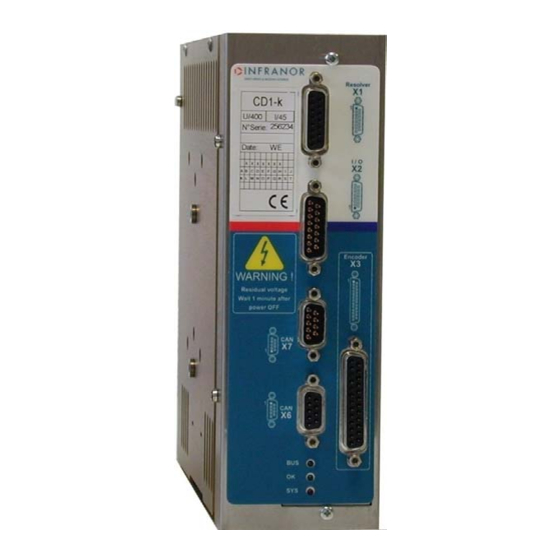
CD1-k – Installation Guide Chapter 3 – Inputs-Outputs 1 - CONNECTORS LOCATION 1.1 - SINGLE-AXIS AMPLIFIERS CD1-k-230-I AND CD1-k-400-I INFRANOR SERVO DRIVES & MOTION CONTROL Resolver CD1-k I: 10.5 U: 400 N°Serie: 200000 Date: I / O RS 232 Encoder... -
Page 16: Led Display
CD1-k- Installation Guide 2 - LED DISPLAY 2.1 - IDENTIFICATION OF THE LEDs BUS (green) OK (green) SYS (red) SYS: System error SYS LED is continuously lit if System error, SYS LED is unlit if no error. OK: Errors are regrouped on the ‘OK’ LED: These errors are coded and can be displayed by means of the parameter setting software, via the serial link RS-232 or via the CANopen bus. -
Page 17: Amplifier Addressing: Selection Of The Transmission Speed
CD1-k – Installation Guide BUS: CANopen RUN LED The CANopen RUN LED indicates the status of the NMT state machine (see DS-301 – 9.52 NMT state machine): CAN RUN LED STATUS SINGLE FLASH STOP 1 000 ms 200 ms FLASHING... -
Page 18: X1 Connector: Resolver Sensor
CD1-k- Installation Guide 4 - X1 CONNECTOR: RESOLVER SENSOR SUB D 15 PINS FEMALE (SAME FOR ALL AMPLIFIER TYPES CD1-k-230/I AND CD1-k-400/I) FUNCTION DESCRIPTION Shield connection If no "360°" connection on the connector S3 (cosine +) Resolver connector S4 (sine -) -
Page 19: Specification Of The Logic Inputs: Inhibit, Fc+, Fc-, Index, Capture, Low Speed
CD1-k – Installation Guide 5.1 - SPECIFICATION OF THE LOGIC INPUTS: INHIBIT, FC+, FC-, INDEX, CAPTURE, LOW SPEED CD1-k 8.2 KΩ Logic input 100 NF 100 KΩ 0 V external (*): 100 pF for Index and Capture These optocoupled inputs are operating in positive logic. -
Page 20: X3 Connectors: Encoder
CD1-k- Installation Guide 6 - X3 CONNECTORS: ENCODER SAME CONNECTORS FOR ALL CD1-k-230/I AND CD1-k-400/I AMPLIFIER TYPES 6.1 - X3 CONNECTOR FOR TTL INCREMENTAL ENCODER & HES INPUT (Sub D 25 pins female) The “ TTL incremental encoder & HES” configuration is software selectable and stored into the amplifier EEPROM. -
Page 21: X3 Connector For Sincos Incremental Encoder & Hes Input (Sub D 25 Pins Female)
CD1-k – Installation Guide 6.2 - X3 CONNECTOR FOR SinCos INCREMENTAL ENCODER & HES INPUT (Sub D 25 pins female) The “ SinCos & HES” incremental encoder configuration is software selectable and stored in the amplifier EEPROM. The corresponding X3 connector pin function is described below. -
Page 22: X3 Connector For Absolute Single-Turn Sincos Encoder (Sub D 25 Pins Female)
CD1-k- Installation Guide 6.3 – X3 CONNECTOR FOR ABSOLUTE SINGLE-TURN SinCos ENCODER (Sub D 25 pins female) The “ SinCos absolute single-turn” incremental encoder configuration (Heidenhain ERN 1085 or compliant) is software selectable and stored in the amplifier EEPROM. The corresponding X3 connector pin function is described below. -
Page 23: X3 Connector For "Pulse / Direction" Inputs (Sub D 25 Pins Female)
CD1-k – Installation Guide 6.4 - X3 CONNECTOR FOR "PULSE / DIRECTION" INPUTS (Sub D 25 pins female) The configuration of the "Pulse / Direction" inputs is software selectable and stored in the amplifier EEPROM. The corresponding X3 connector pin function is described below. -
Page 24: X3 Connector For Encoder Output (Sub D 25 Pins Female)
75-176 X3- 6,7 X3- 5 X3- 19,20 X3- 18 7 - X6 AND X7 CONNECTORS: CAN-OPEN SUB D 9 PINS MALE AND FEMALE (SAME FOR ALL AMPLIFIER TYPES CD1-k-230/I AND CD1-k-400/I) SIGNAL DESCRIPTION CAN-L CAN-L line (dominant low) CAN-GND CAN Ground... -
Page 25: X8 Connector: Auxiliary Supply And Brake
Grounded brake load Imax = 1.5 A 10 - X9 CONNECTOR: POWER CD1-k-230/I: 10 pins male connector with 5.08 mm pitch (female connector provided). CD1-k-400/I: 10 pins male connector with 7.62 mm pitch (female connector provided). CD1-k-400/70 and 90: 10 pins male connector (with 10.16 mm pitch). -
Page 26: Chapter 4 - Connections
Power Power relay Braking resistor Braking dp * Braking resistor resistor Power relay * CD1-k-230/I : 100 ohms / 100 W 230 Vac R Mains 230 Vac 230 Vac S 230 Vac single-phase Power relay Circuit breaker type D I1s = 10 x In In = 10 A (1) CAUTION ! Imax = 100 mA (See AOK output specifications). -
Page 27: Cd1-K-400/I Amplifier
Braking resistor Braking relay resistor Braking resistor CD1-k-400/1.8 to 7.2: dp 200/100 CD1-k-400/14: dp 50/200 CD1-k-400/30 and 45: dp 33/280 CD1-k-400/70 and 90: EF 400 (1) CAUTION ! Imax = 100 mA (see AOK output specifications) Circuit breaker type D I1s = 10 x In ** 10 A for I <... -
Page 28: Connection Of The Serial Link
Battery 30 A/h The consumption of the CD1-k amplifier is 320 mA with 24V . So, a 24 V / 30 A/h battery can keep the amplifier under voltage during i.e. a long 3 days week-end. This backup method is very interesting for saving the machine initialization as well as the axis position even when moving with mains switched off. -
Page 29: Wiring Recommendations
CD1-k – Installation Guide 2 - WIRING RECOMMENDATIONS (according to EN61000.4-2-3-4-5 and EN55011 standards - see diagram "Shield connection on the connectors " – chapter 4, section 2.2). 2.1 - GROUND CONNECTIONS AND GROUNDING CAUTION ! Each potential conducting element must be shielded. Several potential conductors in the same sleeve must be twisted and shielded. -
Page 30: Shield Connection Of The Connectors
CD1-k- Installation Guide 2.2 - SHIELD CONNECTION OF THE CONNECTORS RULE The shield should never be interrupted or corrupted over the whole cable length. Example for the single-axis model: Self-sticking copper ribbon if necessary, for increasing the shield diameter in order... -
Page 31: Connection Vue Of Cd1-K-400/30/45/70 And 90
CD1-k – Installation Guide 2.3 - CONNECTION VUE OF CD1-K-400/30/45/70 AND 90 Br + Br + Br - Br - 2.4 – MOTOR, RESOLVER AND ENCODER CABLES Motors, resolvers and encoders are grounded via their housing. Cable inputs must be made by means of metal connectors with collars allowing the 360° shield connection. -
Page 32: Serial Link And Can Communication Cables
CD1-k- Installation Guide The application requires an Heidenhain linear encoder supplied by 5 V ±5 % / 300mA with 25 m cable length. ∆U Min. power voltage: 5 V ±5 % = 0.25 V . Min. cross section: S = 1.2 mm². -
Page 33: First Powering Of The Amplifier
The green "OK" LED on the front panel must be continuously lit. 3.4 - COMMISSIONING For further details regarding the amplifier commissioning, please see manual CD1-k – User Guide. 4 - REQUIREMENTS FOR THE COMPLIANCE WITH THE UL STANDARDS The UL listing requires the following conditions to be fulfilled by the installer of the amplifiers. -
Page 34: Power Supply And Ul Fuse Rating
CD1-k – Installation Guide 4.3 - POWER SUPPLY AND UL FUSE RATING The fuse type recommended for motor applications is of class RK5. The maximum short-circuit power of the mains must not exceed 5000 Arms at a voltage of 480 V, when protected by a UL fuse of type RK5 and A60Q40 for 400/70 and 400/90 ratings. -
Page 35: Cd1-K-230/I Amplifier: Connection Diagram With Protections By "Ul" Fuses
CD1-k – Installation Guide 4.4 - CD1-k-230/I AMPLIFIER: CONNECTION DIAGRAM WITH PROTECTIONS BY "UL" FUSES (According to section 4.3 of this chapter) CD1-k-230/I UL AOK (1) RESOLVER Motor temp. AOK/ Motor temp. INHIBIT Resolver signal Index 24 V Reference Capture... -
Page 36: Cd1-K-400/I Amplifier: Connection Diagram With Protections By "Ul" Fuses
CD1-k – Installation Guide 4.5 - CD1-k-400/I AMPLIFIER: CONNECTION DIAGRAM WITH PROTECTIONS BY "UL" FUSES (According to section 4.3 of this chapter) CD1-k-400/I UL RESOLVER Motor temp. Motor temp. AOK (1) AOK/ Resolver INHIBIT signal INDEX Resolver 24 V Reference... -
Page 37: Connection Example For A Ul Compliant Multiaxis Application
4.6 - CONNECTION EXAMPLE FOR A UL COMPLIANT MULTIAXIS APPLICATION 24 V 24 V 24 V 24 V Mains For the choice of the fuses, see chapter 4, section 4.3 CD1-k-230/I : 3 x 230 V CD1-k-400/I : 3 x 400 V Chapter 4 - Connections... -
Page 38: Chapter 5 - Appendix
CD1-k- Installation Guide Chapter 5 - Appendix 1 - HARDWARE ADJUSTMENTS OF THE LOGIC BOARD LOGIC BOARD 01685 Chapter 5 – Appendix... -
Page 39: Adjustment To Varioius Resolver Types
CD1-k – Installation Guide 2 – ADJUSTMENT TO VARIOIUS RESOLVER TYPES For the use of other resolvers than those mounted on MAVILOR motors in their standard version, see following wiring diagram of the X1 connector as well as the manufacturer's diagram: For the use of resolvers with transformation ratios out of the range 0.3 to 0.5, the adjustment must be factory... -
Page 40: Energy Recuperation Via A Braking Resistor
CD1-k- Installation Guide 4 - ENERGY RECUPERATION VIA A BRAKING RESISTOR All CD1 amplifiers are equipped with the power feedback system. When the motor is decelerating with high inertia and high speed, the mechanical braking energy is reflected to the amplifier. This energy is dissipated inside a resistor called "braking resistor".
Need help?
Do you have a question about the CD1-k and is the answer not in the manual?
Questions and answers