Table of Contents
Advertisement
Advertisement
Table of Contents

Subscribe to Our Youtube Channel
Related Manuals for Infranor CD1-k


Summary of Contents for Infranor CD1-k
-
Page 1: User Guide
CD1-k User Guide CANopen Amplifier ® INFRANOR CD1-k... - Page 2 This symbol indicates that INFRANOR devices must be eliminated by selective disposal and not with standard waste. INFRANOR does not assume any responsibility for physical or material damage due to improper handling or wrong descriptions of the ordered items. Any intervention on the items, which is not specified in the manual, will immediately cancel the warranty.
-
Page 3: Table Of Contents
CD1-k – User Guide Content PAGE CONTENT ............................... 3 CHAPTER 1 - GENERAL DESCRIPTION ..................... 4 1 - INTRODUCTION..........................4 2 - ARCHITECTURE OF THE AMPLIFIER ..................4 CHAPTER 2 - COMMISSIONING......................6 1 - INSTALLATION OF THE PARAMETER SETTING SOFTWARE............ 6 2 - CHECKING THE AMPLIFIER HARDWARE CONFIGURATION ............ -
Page 4: Chapter 1 - General Description
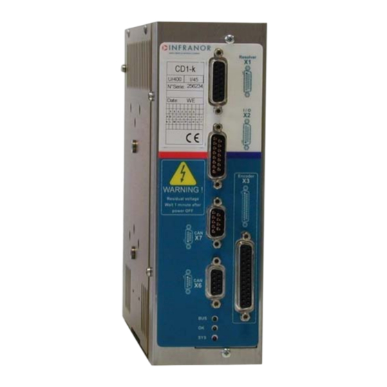
CD1-k all-digital amplifiers with sinusoidal PWM control are servo amplifiers that provide the control of brushless AC motors with position sensor. The CD1-k amplifier is a stand-alone single-axis block including power supply unit and mains filters. It is available in both 230 VAC and 400/480 VAC mains operated voltages. - Page 5 CD1-k – User guide Electric motor Electric device that transforms electrical energy into a mechanical movement. This transformation is often made by means of current commutation. Generally, the movement is a rotation but there are also linear motors. Electric brushless motor. The current commutation is electronically made and Brushless or synchronous requires a position sensor (resolver, encoder, Hall sensor...).
-
Page 6: Chapter 2 - Commissioning
CD1-k – User Guide Chapter 2 - Commissioning CAUTION ! Do not make the amplifier parameter setting by means of both Visual Amplifier Setup software and CANopen bus at the same time. 1 - INSTALLATION OF THE PARAMETER SETTING SOFTWARE ®... -
Page 7: Starting And Adjusting The Amplifier
CD1-k – User Guide 4 - STARTING AND ADJUSTING THE AMPLIFIER This chapter describes the commissioning procedure of the amplifier by means of the " Visual Amplifier Setup" software. • Connect the serial link RS232 between PC and amplifier. •... - Page 8 The encoder counting protection of the CD1-k amplifier range allows the detection of pulse counting errors and immediately disables the amplifier for reasons of security.
- Page 9 CD1-k – User Guide 4.1.4 - PARAMETER ADJUSTMENT FOR A LINEAR MOTOR The Motor encoder resolution parameter is calculated as follows: Motor magnets Pole pitch Motor pole pitch (mm) Motor encoder resolution = 1000 x Encoder signal pitch 1 encoder signal pitch = 4 counting increments...
-
Page 10: I T Protection
CD1-k – User Guide 4.2 - I T PROTECTION 2 selection modes are available: Fusing or Limiting. It is advisable to use the Fusing mode during commissioning phases. In Fusing mode, the amplifier is disabled when the current limitation threshold is reached. -
Page 11: Servo Loop Adjustment
CD1-k – User Guide 4.2.2 - CURRENT LIMITATION IN "LIMITING" MODE When the amplifier output RMS current (I t) reaches 85 % of the rated current, the OK LED on the amplifier front panel is blinking. When the RMS current (I t) drops below 85 % of the rated current, the blinking is inhibited. -
Page 12: Rotation / Counting Direction
CD1-k – User Guide 4.3.2 - LOOP ADJUSTMENT WITH A VERTICAL LOAD In the case of an axis with vertical load, proceed as follows: Select the Limiting current limitation mode. Initialize the speed loop gains corresponding to the unloaded motor (execute therefore the Autotuning procedure with the motor uncoupled from its mechanical load). -
Page 13: Incremental Encoder Outputs
CD1-k – User Guide 7 - INCREMENTAL ENCODER OUTPUTS The incremental encoder outputs are two pulse channels A and B in quadrature and one Z marker pulse per revolution. CW rotation CCW rotation (motor shaft front view) (motor shaft front view) - Page 14 CD1-k – User Guide The Enable cogging torque compensation function allows the commissioning of the motor cogging torque compensation. This function is saved in the amplifier EEPROM. The Save cogging torque data into a file function allows to store in a PC the cogging torque value corresponding to a motor after the acquisition procedure (*.COG file).
-
Page 15: Chapter 3 - Functional Features
In Homing mode, the Index input is used for a homing on the axis. 2 - BRAKE CONTROL The CD1-k amplifier has got a control for the operation of a "powerless" brake. The brake control is enabled (relay open) or disabled (relay closed) according to the amplifier status (enabled or disabled). -
Page 16: Addressing Switch / Speed Selection
CD1-k – User Guide 3 - ADDRESSING SWITCH / SPEED SELECTION Each amplifier of the network must be configured with one single address. A DIP8 switch accessible to the operator allows the configuration of the amplifier address as well as of the of the CANopen bus communication speed. -
Page 17: Chapter 4 - Canopen Communication
CD1-k – User Guide Chapter 4 - CANopen communication For the commissioning of the CANopen communication protocole, please see manual "CD1k – CANopen Communication Profile". Chapter 4 - CANopen communication... -
Page 18: Chapter 5 - Troubleshooting & Maintenance
This fault is displayed by a quick blinking of the OK led. When switching on the auxiliary 24 V supply, the CD1-k amplifier always displays the UNDERVOLT. fault. The UNDERVOLT. Led will go out when switching on the power voltage, after a few seconds time delay that corresponds to the power capacitors soft start. - Page 19 Phase/ground short-circuit. Phase/phase short-circuit. Fan. Power stage short-circuit. Power stage overtemperature (on CD1-k-400/I only). PWM control error. Power stage supply. Braking system error: transistor short-circuit or cycle too high. The VISUAL DRIVE SETUP software allows to identify the “Power stage” fault.
- Page 20 Check for the correct encoder supply voltage value. Check for the correct encoder-amplifier-motor ground and shield connections with regard to the recommendations in chapter 4 of the CD1-k Installation Guide. Check for the correct encoder A channel, B channel and Z marker signal waveforms.
- Page 21 Check for the correct encoder supply voltage value Check for the correct encoder-amplifier-motor ground and shield connections with regard to the recommendations of chapter 4 of the CD1-k Installation Guide. Check for the correct encoder A channel, B channel and R reference signal waveforms.
- Page 22 This error cannot be cancelled. 1.3.13 - "INIT 400V" ERROR If the "INIT 400V" error occurs on a CD1-k 400/I amplifier, at power on: • Check that the amplifier powering has been correctly made.
-
Page 23: Error Reset
CD1-k – User Guide 2 - ERROR RESET A stored error can be cancelled as follows: • by means of the parameter setting software Visual Amplifier Setup, via the serial link RS232, • by means of the RESET function issued from the CANopen bus, •...
Need help?
Do you have a question about the CD1-k and is the answer not in the manual?
Questions and answers