
Related Manuals for Happy HCS-1201-30


Summary of Contents for Happy HCS-1201-30
- Page 1 Maintenance Manual for Embroidery Machine HCS-1201-30 Version 3.0 HAPPY Industrial Corporation...
-
Page 2: For Safe Adjustment And Repair
# For safe adjustment and repair # In order to conduct adjustment and repair safely and surely, please be sure to abide by what is mentioned in this manual to prevent trouble. 1. When you conduct adjustment and repair of this embroidery machine or handle electric related parts, you are required to take technical lesson in advance. -
Page 3: Table Of Contents
Index page cover For safe adjustment and repair Index 3,4,5,6,7 1 Outline of mechanism 1-1 Outline of mechanical mechanism 9,10 1-2 Placement of key electronic parts 2 Outer covers 2-1 Removal of outer covers 13,14,15,16 3 Mechanical mechanism 3-1 Basic maintenance 3-1-1 Maintenance of thread path 19,20 3-1-2 Fixing of needle... - Page 4 Index page 3-2-19 Exchange of thread catcher guide 3-2-20 Disassembling and Cleaning of jump solenoid 3-2-21 Adjustment of bobbin winder 56,57 3-3 Moving head 3-3-1 Assemble the moving head upper rail of 3-3-2 Adjustment of backlash (back and forth) of moving head 3-3-3 Assemble the moving head 61,62,63,64 3-3-4 Adjustment of needle position (back and forth)
- Page 5 Index page 3-6 Thread cut unit 3-6-1 Assemble the arm ass’y 88,89 3-6-2 Exchange of thread cutting roller 90,91,92 3-6-3 Adjustment of spacer ass’y 3-6-4 Adjustment of thread cutting stopper 3-6-5 Adjustment of thread cut timing 95,96 3-6-6 Exchange of moving knife 3-6-7 Exchange of fixed knife 3-6-8 Adjustment of moving knife and fixed knife 3-6-9 Adjustment of position of moving knife...
- Page 6 Index Page 5 Control 5-1 Installment of inverter 5-1-1 How to install inverter 5-1-2 Installment of 100V-120V / VFNC1S 135,136 5-1-3 Installment of 100V-120V / FR-S510W 137,138 5-1-4 Installment of 200V-230V / VFNC1 5-2 Setting of inverter 5-2-1 How to set inverter 5-2-2 FR-S510W / Release of prohibition of parameter setting and its prohibition 5-2-3 FR-S510W / Setting of parameter 5-2-4 FR-S510W / Initialization of parameter...
- Page 7 Index page 6 Electric documents 6-1 Electric system diagram 6-1-1 Electrical connection diagram 6-1-2 List of electrical connection diagrams 6-2 Reference diagram for wiring 6-2-1 Reference diagram for wiring (AC Iine) 6-3 Inverter 6-3-1 VFNC1(S) / Connection of inverter and setting of parameter 6-3-2 FR-S510W / Connection of inverter and setting of parameter 7 Others 7-1 How to respond for some question ( As example step)
-
Page 8: Outline Of Mechanism
1. Outline of mechanism 1-1 Outline of mechanical mechanism 1-2 Placement of key electronic parts 8/204... -
Page 9: Cover
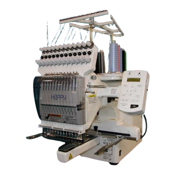
Outline of mechanical mechanism Thread guide bracket Thread guide pillar Tread stand Thread tension unit Moving head Take-up lever Control panel Front cover X carriage Thread adjusting spring Frame base Thread holder Needle plate Rotary hook Rotary hook cover 9/204... -
Page 10: Outline Of Mechanical Mechanism
Outline of mechanical mechanism Needle bar driver unit Y carriage Thread cutting driver Upper shaft Take-up lever cam Thread cacher Needle bar change unit Pressure foot driver unit Thread holder 10/204... -
Page 11: Placement Of Key Electronic Parts
Placement of key electronic parts Pulse motor (Needle bar change unit) PMD board (X) CPU board TC board Display board & ATACF board Emergency stop switch Fuse Pulse motor (Pressure foot ) AC power Power swich Noise filter Timing detecting board Inverter Main motor PMD board (Y) -
Page 12: Outer Covers
2. Outer covers 2-1 Removal of outer covers 12/204... - Page 13 Removal of outer covers 1. Remove thread guide bracket. 3-(2)Disconnect cable. 3-(3) Remove rear panel from arm. 2. Remove thread guide pillar and thread stand. 4. Unscrew screw on arm. 3. Remove control box. 3-(1) Remove front panel. 13/204...
- Page 14 Removal of outer covers 5. Disconnect cable for X carriage. 8. Take off rubber cap. 6. Remove the thread tension ass’y. 9. Remove cover (left). (Remove screw in arrow mark) 7. Remove the guide. 10. Remove cover (right). (Remove screw in arrow mark) 14/204...
- Page 15 Removal of outer covers 11. Remove the cover by pressing an arrow part of 12. Remove the cover (left). the picture. Please keep the machine slant ways slightly. (1) Upper part of the cover Push down the top of cover and side cover a part of nail. (2) Front part of the cover (3) Rear part of the cover Nail shape...
- Page 16 Removal of outer covers 13. Remove the screw of an arrow part of the 16. By above process, removal of [cover] has finished. picture which fixes cover (right). 14. Remove the cover (right), Remove as same procedure as the cover. (left) 15.
-
Page 17: Mechanical Mechanism
3. Mechanical mechanism 3-1 Basic maintenance 3-2 Fixed head 3-3 Moving head 3-4 Needle bar change unit 3-5 Rotary hook 3-6 Thread cut unit 3-7 Carriage unit 3-8 Transmission unit 17/204... -
Page 18: Basic Maintenance
3-1 Basic maintenance 3-1-1 Maintenance of thread path 3-1-2 Fixing of needle 3-1-3 Selection of thread 3-1-4 Relation between needle and upper thread 18/204... -
Page 19: Maintenance Of Thread Path
Maintenance of thread path 3-1-1 In a bid to prevent poor sewing finish or thread break, please keep places where thread contacts in the best condition. 1. Thread tension, detecting roller 4. Thread path in lower side and needle holder. a) Revolution must be smooth a) No burr and crack b) No sticking of lint or dust... -
Page 20: Maintenance Of Thread Path
Maintenance of thread path 3-1-1 6. Needle plate 8. Rotary hook a) No burr and crack in needle hole and around it. a) No burr and crack. b) Hook point not warped. c) Backlash between bobbin case holder and outer hook should be less. -
Page 21: Fixing Of Needle
Fixing of needle 3-1-2 1. In order of (1)-(4), please remove and fix needle. (1) Loosen screw holding needle. (2) Remove needle. (3) Insert needle till it goes to the end. (4) Tighten screw holding needle. Fix needle so that needle groove faces front. Needle holder Needle Front... -
Page 22: Selection Of Thread
Selection of thread 3-1-3 1. Selection of upper thread. <Description> Please select considering cloth, design of pattern and flavour etc. <Thickness> Please refer to [Relation between needle and upper thread 3-1-4]. <Twist> Z twisted thread is to be used. (As rotary hook turns left- wise, Z twisted thread can prevent loosening of twist) Z-twisted S-twisted (Left - twisted) -
Page 23: Relation Between Needle And Upper Thread
Relation between needle and upper thread 3-1-4 1. Description of needle Basically please use [DB X K5] in standard accessory. If description or thickness of cloth doesn't suit needle size, poor sewing finish / thread break / skipping will occur. Therefore careful attention is required in selecting needle. -
Page 24: Fixed Head
3-2 Fixed head 3-2-1 Exchange of crank 3-2-2 Exchange of rod 3-2-3 Adjustment of the lowest needle point 3-2-4 Exchange of needle bar driver 3-2-5 Adjustment of fixing of jump solenoid 3-2-6 Exchange of take-up lever cam 3-2-7 Exchange of roller shaft ass’y 3-2-8 Adjustment of take-up lever timing 3-2-9 Exchange of pressure foot cam 3-2-10 Check of height of pressure foot... - Page 25 Exchange of crank 3-2-1 1. Remove rear cover. 4. Remove moving head. 2. Disconnect TC cable and limit switch cable. <Caution> Do not lost simm material. 3. Remove front cover on front panel. 5. Disconnect cables around thread catcher. 25/204...
- Page 26 Exchange of crank 3-2-1 6. Disconnect LED cable. 7. Remove LED board ass’y. 9. Referring to [3-2-4 Exchange of needle bar driver], remove needle bar driver ass’y. 8. Remove face plate on the left. Installation position should be up and back side. 10.Remove circuit board assembly for timing detecting board.
- Page 27 Exchange of crank 3-2-1 11. Remove power supply. 14. Loosen screw on crank. 15. Pull out upper shaft. (To the extent that crank comes out) 12. Loosen screw on upper shaft collar, upper pulley, drive pulley. 16. Remove bearing retainer. 13.
- Page 28 Exchange of crank 3-2-1 17. Remove crank ass’y. (3)Position of upper pulley is [2mm] from upper shaft collar. Upper pulley positioning gauge [2mm] 18. Put parts once removed back in reverse order For adjusting fixing of each unit, please refer to process (4)Confirm that belt is not interfere the pulley flange and to adjust fixing of each unit.
-
Page 29: Exchange Of Rod
Exchange of rod 3-2-2 1. Referring to [3-2-1 Exchange of crank], remove LED board ass’y, face plate (left) ass’y and moving head. <Caution> Do not lost simm material. 2. Referring to [3-2-4 Exchange of needle bar driver], remove needle bar driver ass’y. 3. -
Page 30: Exchange Of Rod
Exchange of rod 3-2-2 4. Install good parts. <Important> Leave space of [0.03mm] between crank and rod. 5. Put each unit back to where it was according to manual. 30/204... -
Page 31: Adjustment Of The Lowest Needle Point
Adjustment of the lowest needle point 3-2-3 1. Loosen screw on detecting disk. 3. When dial disc reads degree], fix detecting disk. 2. Turn upper shaft so that needle bar driver ass’y comes in the bottom. 4. Work will finish by checking and adjusting timing mentioned below. -
Page 32: Exchange Of Needle Bar Driver
Exchange of needle bar driver 3-2-4 1. Refering to [3-2-1 Exchange of crank], remove LED board ass’y, face plate (left) ass’y and moving head. <Caution> Do not lost simm material. 2. Loosen screw on main shaft in head. 3. Pull out main shaft in head. 32/204... -
Page 33: Exchange Of Needle Bar Driver
Exchange of needle bar driver 3-2-4 4. Loosen screw on lower part of needle bar driver ass’y. 7. Put each unit back according to manual. 8. After exchange, please be sure to adjust needle height. Please refer to [3-3-6 Adjustment of needle height]. <Attention>... -
Page 34: Adjustment Of Fixing Of Jump Solenoid
Adjustment of fixing of jump solenoid 3-2-5 1. Remove rear cover. 4. Remove moving head. 2. Disconnect TC cable and limit switch cable. <Caution> Do not lost simm material. 3. Remove front cover on front panel. 34/204... -
Page 35: Adjustment Of Fixing Of Jump Solenoid
Adjustment of fixing of jump solenoid 3-2-5 5. Remove jump solenoid ass’y. <View from left> This shows a state that plunger and jump body contacts. Plunger Jump body Front side 6. Install good parts. 7. Adjust upper shaft to be [180 degrees] and tip of the body Set upper shaft to... -
Page 36: Exchange Of Take-Up Lever Cam
Exchange of take-up lever cam 3-2-6 1. Remove power supply. 4. Loosen screw on fasten collar for take-up lever cam. 5. Loosen screw on crank. 2. Remove timing detecting board ass’y. 6. Pull out upper shaft (to the extent that shaft comes off from 3. -
Page 37: Exchange Of Take-Up Lever Cam
Exchange of take-up lever cam 3-2-6 7. Remove take up lever cam. (2)Make sure that pulleys and collars are attached without space from machine body except upper pulley. 8. Remove fasten collar. (3)Position of upper pulley is [2mm] from upper shaft collar. -
Page 38: Exchange Of Roller Shaft Ass'y
Exchange of roller shaft ass’y 3-2-7 1. Remove take-up lever crank ass’y. 3. Insert bering positioning gauge [4.85mm] between bering and bering , and then tighten roller shaft ass’y. Please adjust roller shaft for machine front side ways. This roller shaft ass’y is eccentricity. Bering positioning gauge [4.85mm] 4. -
Page 39: Adjustment Of Take-Up Lever Timing
Adjustment of take-up lever timing 3-2-8 1. Loosen screw on fasten collar for take-up lever cam. 4. Turn take up lever cam slowly and insert positioning pin into pin groove. pin groove 2. Set dial disc to degrees]. 5. Loosen screw. <Important>... -
Page 40: Exchange Of Pressure Foot Cam
Exchange of pressure foot cam 3-2-9 1. Remove screw on pressure foot cam. 4. Exchange has finished. 2. Exchange pressure foot cam. 3. Put on grease to pressure foot cam. <Grease> Shell alvania EP Grease2 CODE 613132 Equivalent brand. 40/204... -
Page 41: Check Of Height Of Pressure Foot
Check of height of pressure foot 3-2-10 1. Bring pressure foot down. (Either way mentioned below) 3. Turn upper shaft and set dial disc to degree]. (1)press P_FOOT key on control box. (2)Turn gear with finger. 4. Insert [Gauge I.2mm] between needle plate and pressure foot. -
Page 42: Exchange Of Pressure Foot
Exchange of pressure foot 3-2-11 1. Remove pressure foot. 2. Install good pressure foot. 3. Adjust height of pressure foot to finish. Please refer to [3-2-10 Check of height of pressure foot]. 42/204... -
Page 43: Adjustment Of Height Of Pressure Foot Guide Bar
Adjustment of height of pressure foot guide bar 3-2-12 1. Tighten pressure foot of position for tublar, and then 4. Push down block ass’y. install needle plate for tublar frame. 5. Adjust the center between needle hole of needle plate and hole of pressure foot. -
Page 44: Exchange Of Pressure Foot Link And Block
Exchange of pressure foot link and block 3-2-13 1. Move the head shaft lower. 4. If you remove the pressure foot link B ass’y, first remove the pressure foot cam collar and pressure foot drive cam. 5. Remove pressure foot link B ass’y. 2. - Page 45 Exchange of pressure foot drive lever 3-2-14 1. Remove face plate. After remove pressure foot spring 2, remove pressure foot guide bar to up side. 2.Remove upper rail. 4.Remove sensor board ass’y. 3.Remove pressure foot and pressure foot guide bar. 5.Exchange pressure foot drive lever ass’y.
- Page 46 Exchange of pressure foot drive lever 3-2-14 6. Put on grease to bady and oil bush of pressure foot lever 9. Assemble pressure foot guide bar and pressure foot. ass’y. <Grease> Shell alvania EP Grease2 CODE 613132 Equivalent brand. Oil insert bush 7.
- Page 47 Exchange of pressure foot drive lever 3-2-14 11. Adjust position of pressure foot guide plate A ass’y. 14.Assemble the face plate. <Caution> Make sure that pressure foot guide plate A ass’y is mount perpendicular and parallel to the body. 90 degrees 15.
-
Page 48: Exchange Of Pressure Foot Guide
Exchange of pressure foot guide 3-2-15 1.Remove pressure foot. 4. Remove E-ring (E-4) which fixes guide bar boss. 2. Loosen the screw which fixes guide bar boss. 5.Exchange guide. 3. Remove pressure guide bar. After remove pressure foot spring 2, remove pressure foot guide bar to up side. -
Page 49: Exchange Of Pressure Foot Guide
Exchange of pressure foot guide 3-2-15 7. Adjust the height of pressure foot guide bar to finish. Please refer to [3-2-12 Adjustment of height of pressure foot guide bar.] 49/204... -
Page 50: Exchange Of Pulse Motor For Pressure Foot
Exchange of pulse motor for pressure foot 3-2-16 1.Disconnect cable from Pulse motor and Sensor board ass’y. 4. Remove drive gear A. 2. Down the Pressure foot. 5. Exchange the pulse motor. Fix it temporarily. 3. Remove bracket ass’y. 6. Assemble the drive gear A. The position should come to the middle of the gear range. -
Page 51: Exchange Of Pulse Motor For Pressure Foot
Exchange of pulse motor for pressure foot 3-2-16 7. Adjust position of pulse motor then fix it. Keep slightly backlash between drive geer A and gear. (Every point.) 8. Continue to conduct [Adjust the pressure foot bracket ass’y]. Please refer to [3-2-17 Adjustment of pressure foot bracket ass’y]. -
Page 52: Adjustment Of Pressure Foot Bracket Ass'y
Adjustment of pressure foot bracket ass’y 3-2-17 1. Fix pressure foot bracket ass’y tentatively. <Important> The space between needle plate and pressure foot should be [24.0 - 24.3mm]. Gauge for adjustment of height of pressure foot bracket 2. Lift up pressure foot. 4. -
Page 53: Exchange Of Thread Catcher
Exchange of thread catcher 3-2-18 1. Install thread catcher tentatively. 2. Tighten thread catcher pushing it upward and forward. (As shown an arrow.) 3. Continue to conduct [Adjustment of thread holder]. When you adjustment of thread holder, in case of adjust again thread catcher. -
Page 54: Exchange Of Thread Catcher Guide
Exchange of thread catcher guide 3-2-19 1. Remove guard plate. 4. Please refer to [3-2-18 Exchange of thread catcher], install thread chatcer to finish. 2. Exchange guide. Fix the guide after moving it to the right. 3. Install the guard plate. 54/204... -
Page 55: Disassembling And Cleaning Of Jump Solenoid
Disassembling and Cleaning of jump solenoid 3-2-20 1. Disassemble the solenoid nut. 3. Put the designated grease on plunger part. <Grease> Shell Grease7 MIL-G-23827B CODE 70149 Use rubber sheet as safeguard. Equivalent brand. 4. Assemble the solenoid to the original position. The flat surface of the solenoid nut should come to the front. -
Page 56: Adjustment Of Bobbin Winder
Adjustment of bobbin winder 3-2-21 # Adjust if the thread is leans to one side. 4. Assemble guide as tentatively. 1. Assemble the winder bracket ass’y tentatively. 5. Confirm that the shaft does not touch the cover 2. Assemble the left cover with keeping the space by turning motor. -
Page 57: Adjustment Of Bobbin Winder
Adjustment of bobbin winder 3-2-21 6.Adjust bobbin thread tension [30g] by tension gauge. 9.Adjust the height of Guide to adjust volume of thread to be winded. 7. Rewind the bobbin thread. 10. Reinstall the parts which has been removed. 8. Adjust the inclination of Winder bracket ass’y in accordance with thread winding condition. -
Page 58: Moving Head
3-3 Moving head 3-3-1 Assemble the upper rail of moving head 3-3-2 Adjustment of backlash (back and forth) of moving head 3-3-3 Assemble the moving head 3-3-4 Adjustment of needle position (back and forth) 3-3-5 Check of needle position 3-3-6 Adjustment of needle height 3-3-7 Exchange of needle bar, needle bar spring and cushion 3-3-8 Fixing of needle bar boss guide plate 3-3-9 Exchange of take-up lever... -
Page 59: Assemble The Upper Rail Of Moving Head
Assemble the upper rail of moving head 3-3-1 1. Tighten right and left LM guide base. Follow in picture, keep push to allow way each LM guide base. <Notice> Should be front side which letter on side of LM guide base. 59/204... -
Page 60: Adjustment Of Backlash (Back And Forth) Of Moving Head
Adjustment of backlash (back and forth) of moving head 3-3-2 1. Adjust positioning roller shaft so as to put moving rail (lower) between bearings. Move moving head back and forth so as not to cause backlash. 2. After adjustment, check and adjust needle drop to finish Please refer to [3-3-4 Adjustment of needle position (back and forth) ]. - Page 61 Assemble the moving head 3-3-3 1. Install moving head tentatively. 3. Put in SIMM [0.05mm] between a moving head and LM guide. * Don't tighten a screw only by inserting SIMM here. Please give. <Caution> Screw head not to come out from LM guide side. <View of behind>...
- Page 62 Assemble the moving head 3-3-3 4. Turn the drive shaft B screw for manual operation, <Veiw of left side> and make it the 1st needle. Moving head * When a moving head is caught on the way and does not carry out horizontal movement.
- Page 63 Assemble the moving head 3-3-3 6. Tighten an inside screw (arrow portion in a figure). 7. An outside screw (arrow portion in a figure) is tightened. <important> Please perform a screw bundle in order of "inside to outside." 8. Turn the drive shaft B screw for manual operation, and make it the 12th needles.
- Page 64 Assemble the moving head 3-3-3 At this time, a moving head is pushed from the front and it is 11. Check center (right and left)(back and forth) of needle and LM guide. needle hole of needle plate.(Needle No.1 ,6 and 12.) It is made for there to be no crevice.
-
Page 65: Adjustment Of Needle Position (Back And Forth)
Adjustment of needle position (back and forth) 3-3-4 1. Bring pressure foot down. (Either way mentioned below) 3. Turn upper shaft and set needle near to the lowest needle (1)Press P_FOOT key on control box. position [L] to adjust positioning plate ass’y. (2)Turn gear with finger. -
Page 66: Check Of Needle Position
Check of needle position 3-3-5 1. A main part is turned on. 6. Turn an upper axis up to [302 degrees - 303 "], and it is the The ENT key is pressed and it changes into an operation needle mark to a seal. A hole is made. state. -
Page 67: Adjustment Of Needle Height
Adjustment of needle height 3-3-6 1. Remove lower front panel. 4. Bring needle down. 2. Remove bobbin case. 5. Turn upper shaft to set dial disc to degrees]. 3. Bring pressure foot down. (Either way mentioned below.) (1)Press P_FOOT key on control box. 6. -
Page 68: Adjustment Of Needle Height
Adjustment of needle height 3-3-6 7. Put needle height gauge in rotary hook. About 30 degrees * Check needle holder dose not touch to Needle guard. 10. Tighten the screw of needle bar boss. 8. Adjust the needle bar height up and down till the needle tip touches to the gauge slightly. -
Page 69: Exchange Of Needle Bar, Needle Bar Spring And Cushion
Exchange of needle bar, needle bar spring and cushion 3-3-7 1. Remove rear cover. 4. Remove thread tension bracket. 2. Disconnect TC cable and limit switch cable. 5. Remove lower front paneI. 3. Remove front cover of front panel. 6. Remove needle and needle holder. 69/204... -
Page 70: Exchange Of Needle Bar, Needle Bar Spring And Cushion
Exchange of needle bar, needle bar spring and cushion 3-3-7 7. Loosen needle bar boss and needle bar boss B. 10. Fix needle and needle holder. Needle bar boss B Needle bar boss 11. Adjust needle height. 8. Pull out needle bar. Please refer to [3-3-6 Adjustment of needle height]. -
Page 71: Fixing Of Needle Bar Boss Guide Plate
Fixing of needle bar boss guide plate 3-3-8 1. Remove moving head. 4. Put moving head and other removed parts back to finish. Please refer to [3-3-9 Exchange of take-up lever]. 2. Exchange of needle bar boss guide plate. Temporarily, use the pan head screw to center the needle bar boss guide plate then fix the screw. -
Page 72: Exchange Of Take-Up Lever
Exchange of take-up lever 3-3-9 1. Remove rear cover. 4. Remove thread tension bracket. 2. Disconnect TC cable and limit switch cable. 5. Remove moving head. 3. Remove front cover on front panel. 72/204... -
Page 73: Exchange Of Take-Up Lever
Exchange of take-up lever 3-3-9 6. Loosen screw on take-up shaft. 9. Install take-up lever assembly. 7. Remove the E-ring. 10. Leave space of [0.2mm] between take-up lever and moving head . 8. Remove the take up lever shaft first then remove the take- up lever. -
Page 74: Exchange Of Thread Adjusting Spring
Exchange of thread adjusting spring 3-3-10 1. Remove lower front panel. 4. Remove thread adjusting spring and spring holder. 2. Remove adjuster base. 5. Exchange thread adjusting spring. 3. Remove thread adjusting spring ass’y. 6. Assemble the thread adjusting spring into lower front panel. 74/204... -
Page 75: Exchange Of Thread Adjusting Spring
Exchange of thread adjusting spring 3-3-10 E-ring Washer 7. Put removed parts back in reverse order. 75/204... -
Page 76: Adjustment Of Tension Of Thread Adjusting Spring
Adjustment of tension of thread adjusting spring 3-3-11 1. Remove lower front panel. 2. Block has spring groove to be able to adjust in three steps Put tip of spring in desired position. Strongest tension will be obtained in upper groove. 3. -
Page 77: Adjustment Of Stroke Of Thread Adjusting Spring
Adjustment of stroke of thread adjusting spring 3-3-12 1. Loosen screw on adjuster. 2. Move adjuster position up and down with small frat-head driver to change stroke. When you move adjuster upward,stroke will get small. When you move it down, stroke will get large. 3. -
Page 78: Adjustment Of Thread Holder
Adjustment of thread holder 3-3-13 1. Remove the lower front panel. 4. Hold down the pressurefoot and take the hook in and out by finger to check movement of hook goes smoothly. Check this at 1th , 6 , 12 needle. -
Page 79: Adjustment Of Thread Holder
Adjustment of thread holder 3-3-13 6. Check up with thread trimmer function. 7. Assemble lower front panel to terminate this procedure. 79/204... -
Page 80: Exchange Of Majic-Tape On Thread Holder
Exchange of majic-tape on thread holder 3-3-14 1. Remove the lower front panel. 4. Exchange the majic-tape. <View from bottom> 2. Remove thread holder ass’y. Stick position for velcro strap 5.Assemble holder (lower). 3. Remove holder (lower). <Caution> Refer to above picture for direction of holder (lower). 6. -
Page 81: Needle Bar Change Unit
3-4 Needle bar change unit 3-4-1 Fixing of needle bar change unit 81/204... -
Page 82: Fixing Of Needle Bar Change Unit
Fixing of needle bar change unit 3-4-1 1. Place needle bar change unit assembly. 3. Bring needle down, turn upper shaft to set near to [L point]. please set positioning hole on unit assembly to positioning pin. 4. Adjust position of unit assembly so that needle comes to center against needle hole on needle plate. -
Page 83: Rotary Hook
3-5 Rotary hook 3-5-1 Adjustment of rotary hook timing 3-5-2 Adjustment of retainer on rotary hook 83/204... -
Page 84: Adjustment Of Rotary Hook Timing
Adjustment of rotary hook timing 3-5-1 1. Remove needle plate. 3. Tighten screw on rotary hook. (3 places) 2. Bring pressure foot down. (Either way mentioned below) 4. Bring needle down. (1)Press P_FOOT key on control box. (2)Turn gear with finger. 5. -
Page 85: Adjustment Of Rotary Hook Timing
Adjustment of rotary hook timing 3-5-1 6. Adjust rotary hook timing. This procedure is preconditioned to use needle type [DB-K5] in which contains with our standard accessory. At this moment, clearance between needle and rotary hook should be [0.1-0.15mm]. Check and adjust with 1st, 6th and 12th needle. 0.1-0.15mm 7. -
Page 86: Adjustment Of Retainer On Rotary Hook
Adjustment of retainer on rotary hook 3-5-2 1. Loosen screw to the extent that retainer on bobbin case holder moves. 2. Install screw for Needle plate. (only front side) (This avoid interfere of screw and Rotary hook retainer during installing Needle plate) 3. -
Page 87: Thread Cut Unit
3-6 Thread cut unit 3-6-1 Assemble the arm ass’y 3-6-2 Exchange of thread cutting roller 3-6-3 Adjustment of spacer ass’y 3-6-4 Adjustment of thread cutting stopper 3-6-5 Adjustment of thread cut timing 3-6-6 Exchange of moving knife 3-6-7 Exchange of fixed knife 3-6-8 Adjustment of moving knife and fixed knife 3-6-9 Adjustment of position of moving knife 3-6-10 Adjustment of bobbin thread holder... -
Page 88: Assemble The Arm Ass'y
Assemble the arm ass’y 3-6-1 1. Assemble the arm ass’y. 4. Hold the right side of arm to arrow pointed direction at below picture and tighten screw. screw. Hold arm to backward and tighten only hithermost <Caution> 5. Assemble detecting plate. Make sure that there is clearance between arm and Make sure that detecting plate is mount perpendicular and body. -
Page 89: Assemble The Arm Ass'y
Assemble the arm ass’y 3-6-1 6. Check of interference between detecting plate and sensor or connector of sensor board. A part or conector A part of sensor Sensor 7. Adjust by bending detecting plate by hand if you find any interference with sensor or connector. Detecting plate Conector 8. - Page 90 Exchange of thread cutting roller 3-6-2 1. Remove power supply. 3. Loosen the screw for coupling of the Y carriage. 2. Remove arm. 4. Remove Y carriage bracket (left). 90/204...
- Page 91 Exchange of thread cutting roller 3-6-2 7. Remove drive link ass’y from thread cutting driver ass’y . 5.Remove E-ring. 8. Remove thread cutting driver ass’y . 6.Remove spring. 9. Remove thread cutting roller. 91/204...
- Page 92 Exchange of thread cutting roller 3-6-2 10. Fix good parts. 13.Fix spring and E-ring. 11. Fix thread cutting driver ass’y to the machine. 14. Fix Y carriage bracket (left) to the machine. Fix the base with state of pushing it down. Tighten it on flat surface of motor shaft with screw.
-
Page 93: Adjustment Of Spacer Ass'y
Adjustment of spacer ass’y 3-6-3 1. Fix spacer ass’y. 4. Finish this process. 2. Fix spacer bracket. <Caution> Position of screw should be attached with upper lateral part of thread cutting device (drive arm). 3. Fix it where screw contacts with upper lateral part of thread cutting device (drive arm). -
Page 94: Adjustment Of Thread Cutting Stopper
Adjustment of thread cutting stopper 3-6-4 1.Adjust the thread cut timing. 5.Tighten lock nut. Please refer to [3-6-3 Adjustment of thread cut timing]. 2.Turn upper shaft to set dial disk to [C (275 degrees)]. 6.On checking the clearance [0.2mm] between cam and roller by using 0.2mm thikness gauge. -
Page 95: Adjustment Of Thread Cut Timing
Adjustment of thread cut timing 3-6-5 1. Remove power supply. 4. Turn thread cut cam clock-wise while pushing release lever down. <Important> Push thread cut cam against rotary hook shaft collar A so as not to produce clearance between cam and collar. -
Page 96: Adjustment Of Thread Cut Timing
Adjustment of thread cut timing 3-6-5 6. With release lever being pushed down, turn upper shaft to open and close moving knife repeatedly. 7. On Checking that the knife began to open, at [116 degrees (+0 / -2degrees)] work has finished. 96/204... -
Page 97: Exchange Of Moving Knife
Exchange of moving knife 3-6-6 1. Remove needle plate. 4. Exchange moving knife. 5. Setting drive link hole to moving knife, insert knife drive shaft assembly. 2. Remove knife drive shaft retainer. 6. Pushing down moving knife and knife drive shaft retainer like putting them together, fix knife drive shaft retainer. -
Page 98: Exchange Of Fixed Knife
Exchange of fixed knife 3-6-7 1. Remove needle plate. 4.Tighten fixed knife pushing to forward as full as possible. <Notice> In case moving knife and the left side of fixed knife 2. Remove fixed knife. overlaps excessively when closing, adjust the position of fixed knife slightly to the right direction. -
Page 99: Adjustment Of Moving Knife And Fixed Knife
Adjustment of moving knife and fixed knife 3-6-8 1. Remove needle plate. 2. Check if knife drive shaft has no backlash in up and down direction. If backlash is found, adjust it referring to [3-6-6 Exchange 4. Cut thread and check how well it is cut. of moving knife]. -
Page 100: Adjustment Of Position Of Moving Knife
Adjustment of position of moving knife 3-6-9 1. Loosen screw on link pin. Adjustment of clearance between moving knife and fixed knife is where both tip of then are attached. 2. Turn link pin to adjust position of moving knife. 3. -
Page 101: Adjustment Of Bobbin Thread Holder
Adjustment of bobbin thread holder 3-6-10 1. Remove needle plate. 4. Pull bobbin thread toward arrow mark and see that bobbin thread comes off with tensile gauge [20-25g]. 2. Close moving knife like putting bobbin thread between 5.Tighten lock nut. (Don’t move adjusting screw.) moving knife and bobbin thread holder. -
Page 102: Exchange Of Keeper Solenoid
Exchange of keeper solenoid 3-6-11 1 Disconnect. keeper cable (CN17) on CPU circuit board. 4. Exchange keeper solenoid. <Attention> Pushing keeper solenoid to solenoid base. 2. Remove E-ring on fulcrum pin. Insert 2.0mm thickness gauge between solenoid base to polyslider. 2.0mm thickness gauge 3. -
Page 103: Adjustment Of Position Of Keeper
Adjustment of position of keeper 3-6-12 1. Loosen screw on solenoid base. 4. Adjust solenoid base where tip of keeper contacts slightly to the gauge then tighten bracket screw. Clearance between bobbin and keepr is [about 1.0mm]. 2. Insert [2.0mm] clearance gauge between solenoid base and slider then pull in keeper solenoid and keeper rod. -
Page 104: Carriage Unit
3-7 Carriage unit 3-7-1 Adjustment of X carriage belt tension 3-7-2 Exchange of X carriage belt 3-7-3 Adjustment of Y carriage belt tension 3-7-4 Exchange of Y carriage belt 104/204... -
Page 105: Adjustment Of X Carriage Belt Tension
Adjustment of X carriage belt tension 3-7-1 1. Remove frame base. 4. Remove X carriage cover. 2. Disconnect X carriage cable. 5. Remove sensor bracket. 3. Remove X carriage. 6. Loosen fixing screw for tension pulley bracket slightly. (front side) 105/204... -
Page 106: Adjustment Of X Carriage Belt Tension
Adjustment of X carriage belt tension 3-7-1 7. Loosen fixing screw for tension pulley bracket slightly. Adjustment, tighten fixing screw for tension pulley bracket. (rear side) 9. Tighten fixing screw for tension pulley bracket. (front side) 8. Adjust belt tension. Use push and pull gauge. -
Page 107: Exchange Of X Carriage Belt
Exchange of X carriage belt 3-7-2 1. Remove frame base. 4. Remove X carriage cover. 2. Disconnect X carriage cable. 5. Remove sensor bracket. 3.Remove X carriage. 6. Loosen screw for tension. 107/204... - Page 108 Exchange of X carriage belt 3-7-2 7. Remove the screw which fixes tension bracket. 10. Remove connecting plate. 8. Loosen screw (rear) slightly to the extent that tension- bracket moves. 9. Remove belt from motor pulley. 11. Exchange belt to good one. <Important>...
-
Page 109: Exchange Of X Carriage Belt
Exchange of X carriage belt 3-7-2 12. Adjust the position of belt. Space between edge of X base and belt is [10mm]. 13. Referring to [3-7-1 Adjustment of X carriage belt tension], adjust tension of belt. 14. Return X carriage assembly and frame base to previous places to finish. -
Page 110: Adjustment Of Y Carriage Belt Tension
Adjustment of Y carriage belt tension 3-7-3 1. Remove frame base. 4. Remove arm. 2. Disconnect X carriage cable. 3. Remove X carriage. 110/204... - Page 111 Adjustment of Y carriage belt tension 3-7-3 5. Loosen lock nut for tension adjustment screw. Gauge in the middle of idler pulley. Measurement point Idler pulley (rear) Idler pulley (front) Adjust with screw. 6. Loosen tension screw so as to move tension. 7.
-
Page 112: Adjustment Of Y Carriage Belt Tension
Adjustment of Y carriage belt tension 3-7-3 9. Tighten lock nut for tension adjustment screw. 10. Return arm, X carriage assembly and frame base to previous places to finish. 112/204... -
Page 113: Exchange Of Y Carriage Belt
Exchange of Y carriage belt 3-7-4 1. Remove frame base. 4. Remove arm. 2. Disconnect X carriage cable. 3. Remove X carriage. 113/204... - Page 114 Exchange of Y carriage belt 3-7-4 5. Loosen lock nut for tension adjustment screw. 8. Remove belt holding plate. 9. Exchange belt. 6. Loosen tension screw so as to move tension. 10. Set belt to belt groove of guide frame base. 7.
-
Page 115: Exchange Of Y Carriage Belt
Exchange of Y carriage belt 3-7-4 11. Fix belt holding plate. 12. Referring to [3-7-3 Adjustment of Y carriage belt tension], adjust tension of Y belt. 13. Return arm, X carriage ass’y and frame base to previous places to finish. 115/204... -
Page 116: Transmission Unit
3-8 Transmission unit 3-8-1 Adjustment of timing belt tension 3-8-2 Exchange of timing belt 3-8-3 Adjustment of motor belt tension 3-8-4 Exchange of motor belt 116/204... -
Page 117: Adjustment Of Timing Belt Tension
Adjustment of timing belt tension 3-8-1 1. Remove power supply. 3. Please return power supply to previous places to finish. 2. Adjust tension of timing belt. <Important> Tension shaft ass’y to be set at the center against screw hole of the body. No need to adjust tension. -
Page 118: Exchange Of Timing Belt
Exchange of timing belt 3-8-2 1. Remove power supply. 4. Loosen screw on fasten collar for take-up lever cam. 5. Loosen screw on crank. 2. Remove timing detecting board ass’y. 6. Pull out upper shaft. 3. Loosen screws on upper shaft collar, upper pulley and drive pulley. -
Page 119: Exchange Of Timing Belt
Exchange of timing belt 3-8-2 7. Remove upper pulley and timing belt. (2)Make sure that pulleys and collars are attached without Install good timing belt. space from machine body except upper pulley. (3)Position of upper pulley is [2mm] from upper shaft collar. 8. -
Page 120: Adjustment Of Motor Belt Tension
Adjustment of motor belt tension 3-8-3 1. Remove power supply. 4. Adjust motor belt tension. Use push and pull gauge. <Adjustment value> 320 - 330 g 2. Remove inverter. 3. Loosen screw on motor bracket. Gauge in the near center between drive pulley and motor pulley. -
Page 121: Adjustment Of Motor Belt Tension
Adjustment of motor belt tension 3-8-3 Adjust of tension should be 320 – 330g at belt is pressed 3mm. 6. Return power supply bracket, power supply and inverter Belt is pressed 3mm to previous places to finish. Move main motor upward and downward to adjust. 5. -
Page 122: Exchange Of Motor Belt
Exchange of motor belt 3-8-4 1. Remove power supply. 4. Loosen screw on fasten collar for take-up lever cam. 5. Loosen screw on crank. 2. Remove timing detecting board ass’y. 6. Pull out upper shaft. 3. Loosen screws on upper shaft collar, upper pulley and drive pulley. -
Page 123: Exchange Of Motor Belt
Exchange of motor belt 3-8-4 7. Remove drive pulley and motor belt. (2)Make sure that pulleys and collars are attached without Install good motor belt. space from machine body except upper pulley. (3)Position of upper pulley is [2mm] from upper shaft collar. 8. -
Page 124: Electricity
4. Electricity 4-1 Circuit board related parts 4-2 Sensors 124/204... -
Page 125: Circuit Board Related Parts
4-1 Circuit board related parts 4-1-1 Setting of dip switch for CPU board 4-1-2 Exchange of battery 4-1-3 Setting to fix power supply 125/204... -
Page 126: Setting Of Dip Switch For Cpu Board
Setting of dip switch for CPU board 4-1-1 4 - ON : To use ROM socket inserted ROM OFF : To use circuit board built-in ROM(normal) 3 - ON : Normal OFF : Setting prohibitted 2 - ON : Normal OFF : Write socket inserted ROM in circuit board built-in ROM 1 - ON : No initialization(normal) OFF : To initialize memory with specified value at time of start up... -
Page 127: Setting To Fix Power Supply
Setting to fix power supply 4-1-3 ( Please unplug when you conduct this work) (Please use digital output tester) Notice 1 : Please be sure to put cover on power supply Checking : Before you start to work, please check that terminal plate. -
Page 128: Sensors
4-2 Sensors 4-2-1 Adjustment of upper shaft timing (C point/L point) 4-2-2 Adjustment of TC board 4-2-3 Adjustment of stop position of needle bar change unit 4-2-4 Adjustment of needle bar change sensor 128/204... -
Page 129: Adjustment Of Upper Shaft Timing (C Point / L Point)
Adjustment of upper shaft timing (C point / L point) 4-2-1 1. Remove bobbin thread winding motor ass’y. 5. With this state, turn to C point and check if LED1 Iights between [265 and 282 degrees]. 2. Fix 2 screws tentatively timing detecting board. * Check dose not scratch plastic slit to Timing sensor. -
Page 130: Adjustment Of Tc Board
Adjustment of TC board 4-2-2 Viewing from side of circuit board, set slit so that it comes to center of sensor, fix it. Adjustment of stop position of needle bar change unit 4-2-3 1. Remove potentiometer ass’y. Imagine figure of position sensor and cam 2. -
Page 131: Adjustment Of Needle Bar Change Sensor
Adjustment of needle bar change sensor 4-2-4 1. Set moving head 12 needle. 3. Viewing potentiometer from shaft, turn clock-wise till it stops. 4. From its stop position, make it one turn counter-clock-wise. 2.Disconnect cable. Then remove potentiometer ass’y. 5. With it as is, insert it in the machine, put shaft firmly and hold plate B. -
Page 132: Control
5. Control 5-1 Installment of inverter 5-2 Setting of inverter 5-3 Initialization of system 5-4 Revolution 5-5 Setting to detect needle position 5-6 Maintenance mode 5-7 Detection of power outage 132/204... -
Page 133: Installment Of Inverter
5-1 Installment of inverter 5-1-1 How to install inverter 5-1-2 Installment of 100V-120V / VFNC1S 5-1-3 Installment of 100V-120V / FR-S510W 5-1-4 Installment of 200V-230V / VFNC1 133/204... -
Page 134: How To Install Inverter
How to install inverter 5-1-1 <NOTICE> Installment procedure of Inverter depends on machine voltage, 100V or 200V. In case of 100V machine, it also depends on the type of the inverter to be installed. Confirm Model no. and voltage of the Inverter before Installment. * Refer to [5-1-4] VFNC1 TYPE for machine voltage 200-230V. -
Page 135: Installment Of 100V-120V / Vfnc1S
Installment of 100V - 120V / VFNC1S 5-1-2 (Please unplug when you conduct this work) 4.Fix Inverter with screw and bushing. (Fix 2 points below marked.) <Checking> Before you start to work,please check that charge lamp is off. Charge lamp <Notice>... -
Page 136: Installment Of 100V-120V / Vfnc1S
Installment of 100V - 120V / VFNC1S 5-1-2 6. Connect signal cable. (Refer to article 6-3-1) R----BROWN P5----GREEN CC----WHITE S1----ORENGE FLC---BLACK CC----PURPLE CC----YELLOW FLA---GLAY VI/S3-BLUE <Notice> After checking that power and inverter match voltage to be used, please turn power on. 100 - 120V Power supply Inverter (VFNC1S) - Page 137 Installment of 100V - 120V / FR-S510W 5-1-3 (Please unplug when you conduct this work) 4. Fix support bracket A. <Checking> Before you start to work,please check that display is off. 1.Remove Inverter cover. 5.Fix support bracket B to Inverter. Inverter and Bracket are assembled before parts supplying.
- Page 138 Installment of 100V - 120V / FR-S510W 5-1-3 8. Connect motor cable. (Refer to article 6-3-2) <Notice> After checking that power and inverter match voltage to # In case of motor cable being black, white and gray. be used, please turn power on. 100 - 120V W GLAY Power supply...
-
Page 139: Installment Of 200V-230V / Vfnc1
Installment of 200V - 230V / VFNC1 5-1-4 (Please unplug when you conduct this work) # In case of motor cable being red, white and black. W/T3 BLACK <Checking> Before you start to work,please check that charge lamp Is off. V/T2 WHITE Charge lamp U/T1 RED... -
Page 140: Setting Of Inverter
5-2 Setting of inverter 5-2-1 How to set inverter 5-2-2 FR-S510W / Release of prohibition of parameter setting and its prohibition 5-2-3 FR-S510W / Setting of parameter 5-2-4 FR-S510W / Initialization of parameter 5-2-5 VFNC1(S) / Release of prohibition of parameter setting and its prohibition 5-2-6 VFNC1(S) / Setting of basic parameter 5-2-7 VFNC1(S) / Setting of expansion parameter 5-2-8 VFNC1(S) / Initialization of parameter... -
Page 141: How To Set Inverter
5-2-1 In case of spare parts supply, parameter is preset. Please contact HAPPY, when you need to change it. Parameter cannot be set while machine is running . Pay attention to electric wires as setting is done with power is on. -
Page 142: Fr-S510W / Release Of Prohibition Of Parameter Setting And Its Prohibition
5-2-2 FR-S510W / Release of prohibition of parameter setting and its prohibition How to release prohibition of setting. 1. Press “Mode” button to display [P **]. 5. Press “SET” button to write preset value. (3-time pressing enables you to go back to initial display) Alternate display will come during writing. -
Page 143: Fr-S510W / Setting Of Parameter
FR-S510W / Setting of parameter 5-2-3 Please note that parameter cannot be set while machine is running. Set parameter after releasing prohibition of parameter setting (Refer to 5-2-2). Refer to [6-3-2] for preset value. If you have done initialization of parameter FS-S510W, please set [P30=1] , [P79=2] , [P77=2] before setting other parameters. -
Page 144: Fr-S510W / Initialization Of Parameter
FR-S510W / Initialization of parameter 5-2-4 Please note that parameter cannot be set while machine is running. Set parameter after releasing prohibition of parameter setting (Refer to 5-2-2). In case of mis-setting, parameter can be reset at one time by initialization. Then change it to required parameter. 1. -
Page 145: Vfnc1(S) / Release Of Prohibition Of Parameter Setting And Its Prohibition
5-2-5 VFNC1(S) / Release of prohibition of parameter setting and its prohibition This is to release setting normally prohibited. 4. Press “ ” button to set to display of [F700]. 1. Press “MON” button to display AUH. (When you press three times, display will make one round) 5. -
Page 146: Vfnc1(S) / Setting Of Basic Parameter
VFNC1(S) / Setting of basic parameter 5-2-6 Please note that you are unable to make this setting while the machine is running. Please set with prohibition of parameter setting released (reference to 5-2-5). Basic parameter is to be set by setting items without F***. Please refer to article 6-3-1 for setting value. 4. -
Page 147: Vfnc1(S) / Setting Of Expansion Parameter
VFNC1(S) / Setting of expansion parameter 5-2-7 Please note that you are unable to make this setting while the machine is running. Please set with prohibition of parameter setting released (reference to 5-2-5). Expansion parameter is to be set by setting items with F***. Please refer to article 6-3-1 for setting value. 1. -
Page 148: Vfnc1(S) / Initialization Of Parameter
VFNC1(S) / Initialization of parameter 5-2-8 Please note that you are unable to make this setting while the machine is running. Please set with prohibition of parameter setting released (reference to 5-2-5). When setting is mistakenly made in mid way, the setting will return to parameter in normal standard in one action. Thereafter please change to parameter you want to set. -
Page 149: Initialization Of System
5-3 Initialization of system 5-3-1 Process for updating program 5-3-2 Initialization of memory 5-3-3 Re-writing of program (Control-program / built-in embroidery letter) 149/204... -
Page 150: Process For Updating Program
Process for updating program 5-3-1 * Work sequence of Updating Program are described below. Refer to manual for setup steps of every particular items. 1. Install Updated EP-ROM at the ROM socket of CPU board. Change dip-switch [DSW2 into OFF] [DSW4 into ON] of CPU board and turn on power. Program will be rewritten automatically. -
Page 151: Initialization Of Memory
Initialization of memory 5-3-2 At time of start-up, this is to initialize work memory to specified value. Initialization takes place when there is something wrong in machine action. After finishing initialization, settings such as number of revolution and detection of needle position become initial value. So please set again. 1. -
Page 152: Re-Writing Of Program (Control-Program / Built-In Embroidery Letter)
5-3-3 Re-writing of program (Control-program / Built-in embroidery letter) Re-writing is required when you make version-up of Control-program and Built-in embroidery letter or replace CPU board. If you don't clear inner memory,it will be likely <Judgment by circuit board itself> to cause malfunction. -
Page 153: Revolution
5-4 Revolution 5-4-1 Adjustment of revolution 153/204... -
Page 154: Adjustment Of Revolution
Adjustment of revolution 5-4-1 It will be required to set revolution of main shaft to match the machine. If revolution is not set, number of revolution may not rise. 1. Turn power on. After the machine started to run, press “MENU” button. 2. -
Page 155: Setting To Detect Needle Position
5-5 Setting to detect needle position 5-5-1 Setting to detect needle position (for 12 needles) 155/204... -
Page 156: Setting To Detect Needle Position (For 12 Needles)
Setting to detect needle position (for 12 needles) 5-5-1 It is necessary to store value of needle selection sensor according to number of needles. If this setting is not made, normal needle selection may not be made. 7. Press “ ”... -
Page 157: Setting To Detect Needle Position (For 12 Needles)
Setting to detect needle position (for 12 needles) 5-5-1 11. Press “ ” button to get No: E, Press “ENT” button with display of E to store value of sensor at the 12th needle. (When writing setting value, display disappears for an instant.) 12. -
Page 158: Maintenance Mode
5-6 Maintenance mode 5-6-1 How to install maintenance mode 5-6-2 Machin - Motion of machine 5-6-3 Memory - Checking of memory space and clearing all 5-6-4 Record - Display of data of machine in operation 5-6-5 Other - Setting of machine 158/204... -
Page 159: Maintenance Mode
Maintenance mode We have 5 maintenance modes as mentioned below. Machin Motion of machine Angle Display of machine angle (No use for basic maintenance service.) Memory Checking of memory space and clearing all Record Display of data of machine in operation Other Setting of machine How to install maintenance mode... -
Page 160: Machin - Motion Of Machine
Machin - Motion of machine 5-6-2 The machine has following individual actions. As actuators such as motor etc. may work, please put the machine in motion to check that there is no problem, then start. It is dangerous to approach the machine while it is in motion. Please keep your face and hands off from it in motion. -
Page 161: Memory - Checking Of Memory Space And Clearing All
Memory - Checking of memory space and clearing all 5-6-3 Checking that work and action of pattern memory area are correct, please clear all. After clearing, when you turn power on, E-120 is displayed. After display, please turn power on again. When you face situation that you can't put pattern in or pattern was destroyed, or when you replace CPU circuit board, please conduct this mode. -
Page 162: Record - Display Of Data Of Machine In Operation
Record - Display of data of machine in operation 5-6-4 You can confirm history of operation of the machine in the past. Record Thread Pattern Number of stitch of thread break at 16places in the past. Needle Accumulated total of thread break of a needle. Error : Error and date that had occurred in the past 30 cases 1. -
Page 163: Other - Setting Of Machine
Other - Setting of machine 5-6-5 This is to make basic setting of the machine. As we use flash memory for writing, contents are not cleared even if clearing all memories are conducted. If you want to change contents further, please obtain approval from manufacturers. Contents Head Number of heads (in case of HCS, 1 head) -
Page 164: Detection Of Power Outage
5-7 Detection of power outage 5-7-1 Adjustment of power outage detection 164/204... -
Page 165: Adjustment Of Power Outage Detection
Adjustment of power outage detection 5-7-1 * Please use digital output tester. 1. Please use 24V power tester to check [24.6V±0.1V]. (If different, please re-adjust referring to 4-1-3) 2. Turn switch to the left as full as possible. 3. Put plus terminal to TP1 on circuit board and minus terminal to GND. Turn switch slowly and set to area where tester indicates [1.5V±0.1V]. -
Page 166: Electric Documents
6. Electric documents 6-1 Electric system diagram 6-2 Reference diagram for wiring 6-3 Inverter 166/204... -
Page 167: Electric System Diagram
6-1 Electric system diagram 6-1-1 Electrical connection diagram 6-1-2 List of electrical connection diagrams 167/204... -
Page 168: Electrical Connection Diagram
Electrical connection diagram 6-1-1 168/204... -
Page 169: List Of Electrical Connection Diagrams
List of electrical connection diagrams 6-1-2 169/204... -
Page 170: Reference Diagram For Wiring
6-2 Reference diagram for wiring 6-2-1 Reference diagram for wiring (AC Iine) 170/204... -
Page 171: Reference Diagram For Wiring (Ac Iine)
Reference diagram for wiring (AC Iine) 6-2-1 171/204... -
Page 172: Inverter
6-3 Inverter 6-3-1 VFNC1(S) / Connection of inverter and setting of parameter 6-3-2 FR-S510W / Connection of inverter and setting of parameter 172/204... -
Page 173: Vfnc1(S) / Connection Of Inverter And Setting Of Parameter
VFNC1(S) / Connection of inverter and setting of parameter 6-3-1 173/204... -
Page 174: Fr-S510W / Connection Of Inverter And Setting Of Parameter
FR-S510W / Connection of inverter and setting of parameter 6-3-2 174/204... -
Page 175: Others
7. Others 7-1 How to respond for some question (As example step) 7-2 Trouble shooting 7-3 Error 7-4 Reference date 175/204... -
Page 176: How To Respond For Some Question ( As Example Step)
How to respond for some question (As example step) *When you receive some question from customer, please use this step for sold problem as sample. Receive contact from customer Ask machine serial number Ask contents of question *Circumstance of machine (Windy, Dusty, Floor condition and etc) *Embroidery condition (Frame, Fabric, Thread, Pattern) *Machine creations. -
Page 177: Trouble Shooting
7-2 Trouble shooting 7-2-1 Electricity doesn’t turn on 7-2-2 Thread break 7-2-3 Erroneous thread cut 7-2-4 Off-registration of pattern 7-2-5 Upper thread comes off from needle hole 7-2-6 Upper thread remains 7-2-7 Malfunction of thread break detection 7-2-8 Suspension of upper shaft 7-2-9 Malfunction of needle bar change 7-2-10 Defect on thread catcher 7-2-11 Others (Mechanical) -
Page 178: Electricity Doesn't Turn On
Trouble shooting(Electricity doesn’t turn on) 7-2-1 Trouble Factor Cause of trouble and measure Page Electricity 1. Did fuse blow? Mechanical doesn't turn on 1-1 If it did, replace it. 2. Check of defect on board. 2-1 Replace of CPU board. 2-2 Replace of display board. -
Page 179: Thread Break
Trouble shooting(Thread break) 7-2-2 Trouble Factor Cause of trouble and measure Page Thread break 1. Is needle drop unstable by vibration? (2-4) Mechanical 1-1 Reconsider where to install the machine. 1-2 Move the machine to floor fully reinforced. 1-3 Use strong table to be able to endure vibration. 2. - Page 180 Trouble shooting(Thread break) 7-2-2 Trouble Factor Cause of trouble and measure Page Thread break 11. No problem in rotary hook? 3-1-1 Mechanical 11-1 Clean it to remove lints. (10-2) 11-2 Furbish scratch. 11-3 If backlash of bobbin case holder and outer hook grows bigger, replace them. 11-4 Replace.
- Page 181 Trouble shooting(Thread break) 7-2-2 Trouble Factor Cause of trouble and measure Page Thread break 24. Check tip of keeper hit the bobbin case. Mechanical 24-1 Adjust it regularly. 25. ls take-up lever timing proper ? 25-1 Adjust as specified. 3-2-7 26.
- Page 182 Trouble shooting(Thread break) 7-2-2 Trouble Factor Cause of trouble and measure Page Thread break Operator 10. Is frame used to suit pattern size? 10-1 Use frame to suit pattern size. 11. When you dispose of thread (thread remains around rotary hook), didn't you damage rotary hook, needle plate with scissors? 11-1 Tell to dispose of thread carefully.
-
Page 183: Thread Break
Trouble shooting(Thread break) 7-2-2 Trouble Factor Cause of trouble and measure Page Thread break . Is there something that produce steam, wasted cotton, dust around. Environment the embroidery machine? 5-1 Keep the embroidery machine off those things. (2-5) 5. Does thread go out of control by taking wind from outside or heater etc.? (2-5) 6-1 Keep the embroidery machine off such wind. - Page 184 Trouble shooting(Erroneous thread cut) 7-2-3 Trouble Factor Cause of trouble and measure Page Erroneous 1. Is thread cut timing proper? Mechanical thread cut 1-1 Set timing to specified value. 3-6-3 (E-190) 1-2 Check no loosening of screw on thread cut cam. (E-193) 2.
- Page 185 Trouble shooting(Erroneous thread cut) 7-2-3 Trouble Factor Cause of trouble and measure Page Erroneous 12. Check the needle bar moves up and down during thread cut. Mechanical thread cut 12-1 Adjust position of jump solenoid. 3-2-5 (E-190) 12-2 Replace needle bar cushion. 3-3-4 (E-193) 12-3 Replace needle bar driver.
-
Page 186: Off-Registration Of Pattern
10-1 Check wiring. If screw got loosened, tighten more. 10-2 After 10-1, still problem, then replace. 11. Does't other frame than Happy's genuine one used? 11-1 If frame is too heavy, don't use it. 11-2 If setting is not proper, set it so as not to move. -
Page 187: Off-Registration Of Pattern
Trouble shooting(Off-registration of pattern) 7-2-4 Trouble Factor Cause of trouble and measure Page Off-registration Operator 2. Is cloth properly stretched. (6-2) (7-5) of pattern 2-1 Stretch properly. 3. Is thread tension proper? (4-5) (8-1) 3-1 Observing sewing rhythm, set thread tension properly. 4. -
Page 188: Upper Thread Comes Off From Needle Hole
Trouble shooting(Upper thread comes off from needle hole) 7-2-5 Trouble Factor Cause of trouble and measure Page Upper thread 1. Is keeper in motion? Mechanical comes off 1-1 Check if cable was cut or there is something unusual. from needle 1-2 In case solenoid is in trouble, replace. -
Page 189: Upper Thread Comes Off From Needle Hole
Trouble shooting(Upper thread comes off from needle hole) 7-2-5 Trouble Factor Cause of trouble and measure Page Upper thread 11.Check the needle bar moves when start sewing. Mechanical comes off 11-1 Adjust position to fix jump solenoid. 3-2-5 from needle 11-2 Replace needle bar driver. -
Page 190: Upper Thread Remains
Trouble shooting(Upper thread remains) 7-2-6 Trouble Factor Cause of trouble and measure Page Upper thread Mechanical Upper thread is difficult to come out of keeper at time of thread cut (bent or warp etc.). remains 1-1 Modify bent or warp. 1-2 Replace keeper. -
Page 191: Malfunction Of Thread Break Detection
Trouble shooting(Malfunction of thread break detection) 7-2-7 Trouble Factor Cause of trouble and measure Page Malfunction 1. Trouble in turning detection roller. Mechanical thread break 1-1 Clean roller shaft holder. detection 1-2 Check if slit disc doesn't contacts sensor. 4-2-2 (empty 1-3 Clean sensor if dust gets stuck. -
Page 192: Malfunction Of Thread Break Detection
Trouble shooting(Malfunction of thread break detection) 7-2-7 Trouble Factor Cause of trouble and measure Page Malfunction 1. Check circuit board. Mechanical thread break 1-1 Replace of CPU board. detection 1-2 Replace of TC 12 board. (not detected) Operator 1. Is thread tension proper? (slow detected) 1-1 Observing sewing rhythm, adjust to proper thread tension. -
Page 193: Suspension Of Upper Shaft
Trouble shooting(Suspension of upper shaft) 7-2-8 Trouble Factor Cause of trouble and measure Page Suspension 1. Upper thread twine round rotary hook or rotary hook retainer. Mechanical of main shaft 1-1 Get rid of it. (E-18) 2. Check return of keeper goes smooth. (when start sewing.) (E-51) 2-1Adjust it regularly. -
Page 194: Malfunction Of Needle Bar Change
Trouble shooting(Malfunction of needle bar change) 7-2-9 Trouble Factor Cause of trouble and measure Page Head does not 1. Check lint or cloth is seized between Lower Moving rail and Bearing. Mechanical move 1-1 Remove seized lint or cloth. (E-021) 2. -
Page 195: Defect On Thread Catcher
Trouble shooting(Defect on Thread catcher) 7-2-10 Trouble Factor Cause of trouble and measure Page does not catch 1. Thead catcher does not extend hook sufficiently. Mechanical thread 1-1 Adjust position of Thread catcher . 1-2 Adjust position of Thread holder. 2. -
Page 196: Others (Mechanical)
Trouble shooting(Others / Mechanical) 7-2-11 Trouble Factor Cause of trouble and measure Page 1. Check Needle is not bent. Needle Breakage Mechanical 1-1 Replace bent Needle. 3-1-2 2. Check Moving Head set securely. 2-1 Adjust Positioning Roller Shaft. 3-3-1 3. Secure adequate distance between Needle and Rotary Hook. 3-1 Adjust distance properly. - Page 197 2. No trouble in memory tip on CPU board? 2-1 Conduct [memory all clear] in maintenance mode. 5-5-3 2-2 If above measure doesn't solve the trouble, replace CPU circuit board. ) ----- Reference instruction book P**-P** --- Refer to Happy Link instruction book 197/204...
-
Page 198: Error
7-3 Error 7-3-1 Error and measure 198/204... -
Page 199: Error And Measure
Error and measure 7-3-1 When trouble occurred while the machine is running, error number and error item will be displayed. After confirming contents, press key [ENT.] on control box to release error, then restore in accordance with measure in this list. Message Error Measure... - Page 200 Error and measure 7-3-1 message Error measure page Slow mismatch Inadequate adjustment of number of (1)Make automatic speed setting. 5-3-1 low speed revolution. (2)If not solved even after speed adjustment, (11-1)(11-2) Low speed revolution doesn't come replace CPU circuit board. below 100rpm.
-
Page 201: Error And Measure
Error and measure 7-3-1 message Error measure page Change over While reading pattern data, the Modify pattern data and reduce frequency of color frequency of color change (color No.) change of one pattern to less than 250 times. exceeded 250 times. Divide pattern data and reduce frequency of color change of one pattern to less than 250 times. -
Page 202: Reference Date
7-4 Reference date 7-4-1 Tables for timing / adjustment value 202/204... -
Page 203: Tables For Timing / Adjustment Value
Tables for timing / adjustment value 7-4-1 Tables for Timing/Adjustment value Take-up lever timing 10 degrees Rotary hook timing 25 degrees Needle height 5 degrees Thread cut timing 116 degrees (+0 / -2degrees) LED2 light out at 0 degrees Main shaft timing LED1 light on at 265-282 degrees 200g Carriage... - Page 204 Maintenance Manual for Embroidery Machine HCS-1201-30 2004 / 10 HAPPY Industrial Corporation 9-5. TAITO 2-CHOME,TAITO-KU,TOKYO,JAPAN TEL 81-3-3834-0711 FAX 81-3-3835-8917 204/204...
Need help?
Do you have a question about the HCS-1201-30 and is the answer not in the manual?
Questions and answers
How to load a logo
To load a logo on the Happy HCS-1201-30 embroidery machine:
1. Transfer the embroidery file containing the logo to the machine using Happy Link software via USB or LAN connection.
2. Insert the hoop with fabric into the machine and lock it into place.
3. Use the machine menu to select the design. You can bring up the file and check it on the screen.
4. Use the Trace mode to verify the design fits within the hoop area.
5. Once confirmed, press the Start button to begin stitching.
The machine displays design progress, stitch count, upcoming thread colors, current needle, and speed during operation.
This answer is automatically generated