Advertisement
Quick Links
Advertisement

Related Manuals for Happy HCS2-1201-30


Summary of Contents for Happy HCS2-1201-30
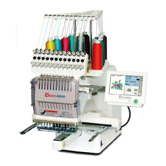
- Page 1 Maintenance Manual for Embroidery Machine HCS2-1201-30 Version 2. 3 HappyJapan Inc.
- Page 2 # For safe adjustment and repair # In order to conduct adjustment and repair safely and surely, please b42e sure to abide by what is mentioned in this manual to prevent trouble. 1. When you conduct adjustment and repair of this embroidery machine or handle electric related parts, you are required to take technical lesson in advance.
- Page 3 Index page For safe adjustment and repair Index Special tool, Measuring equipment, Other 1 Outline of mechanism 1-1 Placement of key mechanical parts 1-2 Placement of key electronic parts 2 Outer covers 2-1 Removal of outer covers 3 Mechanical mechanism 3-1 Basic maintenance 3-1-1 Maintenance of thread path 3-1-2 Fixing of needle...
- Page 4 Index page 3-2-19 Exchange of thread catcher guide 3-2-20 Disassembling and Cleaning of jump solenoid 3-2-21 Adjustment of bobbin winder 3-3 Moving head 3-3-1 Assemble the moving head upper rail of 3-3-2 Adjustment of backlash (back and forth) of moving head 3-3-3 Assemble the moving head 3-3-4 Adjustment of needle position (back and forth) 3-3-5 Check of needle position...
- Page 5 Index page 3-6 Thread cut unit 3-6-1 Assemble the arm ass’y 3-6-2 Exchange of thread cutting roller (except for Rev.A) 3-6-3 Exchange of thread cutting roller (for Rev.A) 3-6-4 Adjustment of thread cutting stopper (except for Rev.A) 3-6-5 Adjustment of thread cut timing (except for Rev.A) 3-6-6 Exchange of moving knife 3-6-7 Exchange of fixed knife 3-6-8 Adjustment of moving knife and fixed knife...
- Page 6 Index Page 4-3 Inverter 4-3-1 Remove of Inverter 4-3-2 Inverter Installation 4-3-3 How to set inverter 4-3-4 Initialization of parameter 4-4 Initialization of system 4-4-1 Program update procedure 4-4-2 Preparation for program update 4-4-3 Machine program update (Main program 〜Ver.*1.21) 4-4-4 Main program update (Main program 〜Ver.*1.21) 4-4-4a Machine program and Main program update (Main program Ver.*1.22〜) 141a...
- Page 7 Index Page 6 Others 6-1 How to respond for some question ( As example step) 6-2 Trouble shooting 6-2-1 Electricity doesn’t turn on 6-2-2 Thread break 6-2-3 Erraneous thread cut 6-2-4 Off-registration of pattern 6-2-5 Upper thread comes off from needle hole 6-2-6 Upper thread remains 6-2-7 Malfunction of thread break detection 6-2-8 Suspension of upper shaft...
- Page 8 Special tool, Measuring equipment, Other HSA90010 HSA90051 Needle bar boss positioning gauge [25mm] (Page 65) Bering positioning gauge [4.85mm] (Page 36) HSA90061 HSA90020 Gauge for adjustment of height of pressure foot bracket 2.0mm thickness gauge (Page 102, 103) [24.8 - 25.0mm] (Page 50) HSA90071 HSA90030 Thread hoIder positioning gauge [47.5mm]...
- Page 9 HSA90080 HSA90200 Retainer positioning gauge [0.8mm] (Page 82) 0.03mm thickness gauge (Page 28) HSA90090 HSA90210 Positioning pin (Page 37) 0.2mm thickness gauge (Page 70, 91) HSA90131 HSA90230 1.2mm thickness gauge (Page 39, 41, 45, 47) Tensile gauge (Page 55, 101)
- Page 10 HSA90311 HSA90240 Shell alvania EP Grease 100g Dial-gauge set (Page 29) (Page 38, 44) HSA90340 HSA90270 Shell Grease7 MIL-G-23827B 50g Vernier calliper gauge [200mm] (Page 53) HSA90280 HSA90321 Tension gauge 1000cN (Page 105, 110, 118) 11.5mm thickness gauge (Page 27 , 35) M0404342 Needle height gauge (Page 65) 10 - 11...
- Page 11 1-1 Placement of key mechanical parts Thread guide bracket Thread guide pillar Tread stand Thread tension unit Moving head Take-up lever Control panel Front cover X carriage Thread adjusting spring Frame base Thread holder Needle plate Rotary hook Rotary hook cover...
- Page 12 Needle bar driver unit Y carriage Thread cutting driver Upper shaft Take-up lever cam Thread cacher Needle bar change unit Pressure foot driver unit Thread holder...
- Page 13 1-2 Placement of key electronic parts Pulse motor (Needle bar change unit) CONT-S2 board TC board Display board Emergency stop switch c ch Fuse Pulse motor (Pressure foot ) Power swich Noise filter AC power Power supply (200V) Timing detecting board Inverter Main motor Power supply (100V)
- Page 14 2-1 Removal of outer covers <Check> Be sure to turn power switch OFF before work. 4. Remove control box. 1. Remove three setscrews of arm E as shown in the figure below. Please reverse procedure when installing control box. 2. Disconnect the connectors indicated by the arrows in the figure below.
- Page 15 5. Remove thread guide bracket. 8. Disconnect cable for X carriage. 6. Loosen a screw of thread guide pillar 9. Remove 2 screws, then take the X carriage off. 7. Remove thread guide pillar and thread stand. 10. Remove the thread tension ass’y.
- Page 16 11. Remove the guide. 14. Unlock nail of the cover (left) by pressing an arrow point of the cover (right). 12. Take off rubber cap. 15. Remove the cover by pressing an arrow part of the picture. (1) Upper part of the cover (2) Front part of the cover 13.
- Page 17 When the cover is not fixed by screws, please tilt the machine slightly to access locking nail easily. Push down top of the cover and locking nail area as picture below, then the nail will be released from the machine base. 17.
- Page 18 3-1-1 Maintenance of thread path In a bid to prevent poor sewing finish or thread break, please keep places where thread contacts in the best condition. 1. Thread tension, detecting roller 4. Thread path in lower side and needle holder. a) Revolution must be smooth a) No burr and crack b) No sticking of lint or dust...
- Page 19 6. Needle plate 8. Rotary hook a) No burr and crack in needle hole and around it. a) No burr and crack. b) Hook point not warped. c) Backlash between bobbin case holder and outer hook should be less. Surface 9.
- Page 20 3-1-2 Fixing of needle 1. In order of (1)-(4), please remove and fix needle. (1) Loosen screw holding needle. (2) Remove needle. (3) Insert needle till it goes to the end. (4) Tighten screw holding needle. Fix needle so that needle groove faces front. Needle holder Needle Front...
- Page 21 3-1-3 Selection of thread 1. Selection of upper thread. <Description> Please select considering cloth, design of pattern and flavour etc. <Thickness> Please refer to [Relation between needle and upper thread 3-1-4]. <Twist> Z twisted thread is to be used. (As rotary hook turns left- wise, Z twisted thread can prevent loosening of twist) Z-twisted S-twisted (Left - twisted)
- Page 22 3-1-4 Relation between needle and upper thread 1. Description of needle Basically please use [DB X K5] in standard accessory. If description or thickness of cloth doesn't suit needle size, poor sewing finish / thread break / skipping will occur. Therefore careful attention is required in selecting needle.
- Page 23 3-2-1Exchange of crank 1. Remove rear cover. 4. Referring to [3-3-3 Assemble the moving head], remove moving head. 2. Disconnect TC cable and limit switch cable. <Caution> Do not lost simm material. 3. Remove front cover on front panel.
- Page 24 5. Disconnect cables around thread catcher. 7. Referring to [3-2-4 Exchange of needle bar driver], remove needle bar driver ass’y. 6. Remove face plate on the left. Installation position should be up and back side. 8.Remove circuit board assembly for timing detecting board. (As shown an arrow)
- Page 25 9. Remove bobbin winder and power supply. 12. Loosen screw on crank. 13. Pull out upper shaft. (To the extent that crank comes out) 10. Loosen screw on upper shaft collar, upper pulley, drive pulley. 14. Remove bearing retainer. 11. Loosen collar screw on take-up lever cam.
- Page 26 15. Remove crank ass’y. (3)Position of upper pulley is [2mm] from upper shaft collar. (3)Position of upper pulley is space from upper shaft collar. Type of small collar Thickness gauge [11.5mm] (4)Confirm that belt is not interfere the pulley flange and not come out from pulley groove.
- Page 27 3-2-2 Exchange of rod 1. Referring to [3-2-1 Exchange of crank], moving head and 2. Referring to [3-2-4 Exchange of needle bar driver], face plate (left) ass’y. remove needle bar driver ass’y. 3. Loosen screw on rod pin to remove rod. <Caution>...
- Page 28 3-2-3 Adjustment of the lowest needle point 1. Loosen screw on detecting disk. 3. When dial disc reads degree], fix detecting disk. 2. Turn upper shaft so that needle bar driver ass’y comes in the bottom. 4. Work will finish by checking and adjusting timing mentioned below.
- Page 29 3-2-4 Exchange of needle bar driver 1. Refering to [3-2-1 Exchange of crank], moving head and 2. Loosen screw on main shaft in head. face plate (left) ass’y. 3. Pull out main shaft in head. <Caution> Do not lost simm material.
- Page 30 7. Put each unit back according to manual. 4. Loosen screw on lower part of needle bar driver ass’y. 8. After exchange, please be sure to adjust needle height. Please refer to [3-3-6 Adjustment of needle height]. <Attention> Head shaft should be positioned slightly lower than ditch for oil.
- Page 31 3-2-5 Adjustment of fixing of jump solenoid 1. Remove rear cover. 4. Remove moving head. 2. Disconnect TC cable and LED cable. <Caution> Do not lost simm material. 3. Remove front cover on front panel.
- Page 32 5. Remove jump solenoid ass’y. <View from left> This shows a state that plunger and jump body contacts. Plunger Jump body Front side 6. Install good parts. 7. Adjust upper shaft to be [180 degrees] and tip of the body Set upper shaft to degrees] to adjust position of plunger has to be same as the picture below.
- Page 33 3-2-6 Exchange of take-up lever cam 1. Remove bobbin winder and power supply. 4. Loosen screw on fasten collar for take-up lever cam. 5. Loosen screw on crank. 2. Remove timing detecting board ass’y. 6. Pull out upper shaft (to the extent that shaft comes off from 3.
- Page 34 7. Remove take up lever cam. (2)Make sure that pulleys and collars are attached without space from machine body except upper pulley. (3)Position of upper pulley is space from upper shaft collar. Type of small collar 8. Remove fasten collar. Thickness gauge [11.5mm] (4)Confirm that belt is not interfere the pulley flange and not come out from pulley groove.
- Page 35 3-2-7 Exchange of roller shaft ass’y 1. Remove take-up lever crank ass’y. 3. Insert bering positioning gauge [4.85mm] between bering and bering , and then tighten roller shaft ass’y. Please adjust roller shaft for machine front side ways. This roller shaft ass’y is eccentricity. Turn lean screw and just touch roller to gauge.
- Page 36 3-2-8 Adjustment of take-up lever timing 1. Loosen screw on fasten collar for take-up lever cam. 4. Turn take up lever cam slowly and insert positioning pin into pin groove. pin groove 2. Set dial disc to degrees]. 5. Loosen screw. <Important>...
- Page 37 3-2-9 Exchange of pressure foot cam 1. Remove screw on pressure foot cam. 4. Exchange has finished. 2. Exchange pressure foot cam. 3. Put on grease to pressure foot cam. <Grease> Shell alvania EP Grease2 (Shell Gadus S2 V220 2)
- Page 38 3-2-10 Check of height of pressure foot 1. Bring pressure foot down. (Either way mentioned below) 3. Turn upper shaft and set dial disc to degree]. (1)press P_FOOT key on control box. 4. Insert [Gauge I.2mm] between needle plate and pressure (2)Turn gear with finger.
- Page 39 3-2-11 Exchange of pressure foot 1. Remove pressure foot. 2. Install good pressure foot. 3. Adjust height of pressure foot to finish. Please refer to [3-2-10 Check of height of pressure foot].
- Page 40 3-2-12 Adjustment of height of pressure foot guide bar 1. Tighten pressure foot of position for tublar, and then 4. Push down block ass’y. install needle plate for tublar frame. 5. Adjust the center between needle hole of needle plate and hole of pressure foot.
- Page 41 3-2-13 Exchange of pressure foot link and block 1. Move the head shaft lower. 4. If you remove the pressure foot link B ass’y, first remove the pressure foot cam collar and pressure foot drive cam. 5. Remove pressure foot link B ass’y. 2.
- Page 42 3-2-14 Exchange of pressure foot drive lever 1. Remove face plate. After remove pressure foot spring 2, remove pressure foot guide bar to up side. 2.Remove upper rail. 4.Remove sensor board ass’y. 3.Remove pressure foot and pressure foot guide bar. 5.Exchange pressure foot drive lever ass’y.
- Page 43 6. Put on grease to bady and oil bush of pressure foot lever 9. Assemble pressure foot guide bar and pressure foot. ass’y. <Grease> Shell alvania EP Grease2 (Shell Gadus S2 V220 2) Oil insert bush 7. Put on grease to fulcrum shaft. <Caution>...
- Page 44 11. Adjust position of pressure foot guide plate A ass’y. 14. Assemble the face plate. <Caution> Make sure that pressure foot guide plate A ass’y is mount perpendicular and parallel to the body. <Spanner> 7mm 90 degrees 15. Install parts in reverse order to finish. 12.
- Page 45 3-2-15 Exchange of pressure foot guide 1.Remove pressure foot. 4. Remove E-ring (E-4) which fixes guide bar boss. 2. Loosen the screw which fixes guide bar boss. 5.Exchange guide. 3. Remove pressure guide bar. 6.Assemble the pressure foot gude bar and pressure foot. After remove pressure foot spring 2, remove pressure foot guide bar to up side.
- Page 46 7. Adjust the height of pressure foot guide bar to finish. Please refer to [3-2-12 Adjustment of height of pressure foot guide bar.]...
- Page 47 3-2-16 Exchange of pulse motor for pressure foot 1. Disconnect cable from Pulse motor and Sensor board 4. Remove drive gear A. ass’y. 2. Down the Pressure foot. 5. Exchange the pulse motor. Fix it temporarily. 3. Remove bracket ass’y. 6.
- Page 48 7. Adjust position of pulse motor then fix it. Keep slightly backlash between drive geer A and gear. (Every point.) 8. Continue to conduct [Adjust the pressure foot bracket ass’y]. Please refer to [3-2-17 Adjustment of pressure foot bracket ass’y].
- Page 49 3-2-17 Adjustment of pressure foot bracket ass’y <Important> 1. Fix pressure foot bracket ass’y tentatively. The space between needle plate and pressure foot should be [24.8 - 25.0mm]. Gauge for adjustment of height of pressure foot bracket 2. Lift up pressure foot. 4.
- Page 50 3-2-18 Exchange of thread catcher 1. Install thread catcher tentatively. 2. Tighten thread catcher pushing it upward and forward. (As shown an arrow.) 3. Continue to conduct [Adjustment of thread holder]. When you adjustment of thread holder, in case of adjust again thread catcher.
- Page 51 3-2-19 Exchange of thread catcher guide 1. Remove guard plate. 4. Please refer to [3-2-18 Exchange of thread catcher], install thread chatcer to finish. 2. Exchange guide. Fix the guide after moving it to the right. 3. Install the guard plate.
- Page 52 3-2-20 Disassembling and Cleaning of jump solenoid 1. Disassemble the solenoid nut. 3. Put the designated grease on plunger part. <Grease> Shell Grease7 MIL-G-23827B Use rubber sheet as safeguard. Equivalent brand. 4. Assemble the solenoid to the original position. The flat surface of the solenoid nut should come to the front.
- Page 53 3-2-21 Adjustment of bobbin winder # Adjust if the thread is leans to one side. 4. Assemble guide as tentatively. 1. Assemble the winder bracket ass’y tentatively. 5. Confirm that the shaft does not touch the cover by turning motor. (Set the empty bobbin and down the Guide.) 2.
- Page 54 6. Adjust bobbin thread tension [30g] by tension gauge. 9.Adjust the height of Guide to adjust volume of thread to be winded. 7. Rewind the bobbin thread. 10. Reinstall the parts which has been removed. 8. Adjust the inclination of Winder bracket ass’y in accordance with thread winding condition.
- Page 55 3-3-1 Assemble the upper rail of moving head 1. Tighten right and left LM guide base. Follow in picture, keep push to allow way each LM guide base. <Notice> Should be front side which letter on side of LM guide base.
- Page 56 3-3-2 Adjustment of backlash (back and forth) of moving head 1. Adjust positioning roller shaft so as to put moving rail (lower) between bearings. Move moving head back and forth so as not to cause backlash. 2. After adjustment, check and adjust needle drop to finish Please refer to [3-3-4 Adjustment of needle position (back and forth) ].
- Page 57 3-3-3 Assemble the moving head 3. Put in SIMM [0.05mm] between a moving head and 1. P lease c onfirm t hat t he p osition o f n eedle b ar c hange LM guide.
- Page 58 <Veiw of left side> 4. Turn the drive shaft B screw for manual operation, Moving head and make it the 1st needle. * When a moving head is caught on the way and does not carry out horizontal movement. The screw tightened tentatively in "the work procedure 1" has come out from LM guide.
- Page 59 6. Tighten an inside screw (arrow portion in a figure). 7. An outside screw (arrow portion in a figure) is tightened. <important> Please perform a screw bundle in order of "inside to outside." 8. Turn the drive shaft B screw for manual operation, and make it the 12th needles.
- Page 60 At this time, a moving head is pushed from the front and it is 11. Check center (right and left)(back and forth) of needle and LM guide. needle hole of needle plate.(Needle No.1 ,6 and 12.) It is made for there to be no crevice. <Caution>...
- Page 61 3-3-4 Adjustment of needle position (back and forth) 1. Bring pressure foot down. (Either way mentioned below) 3. Turn upper shaft and set needle near to the lowest needle position [L] to adjust positioning plate ass’y. (1)press P_FOOT key on control box. * Insert Lower rail to between the two bearing deeply.
- Page 62 3-3-5 Check of needle position 6. Turn an upper axis up to [302 degrees - 303 "], and it is the A main switch is turned on. needle mark to a seal. A hole is made. is pressed and it changes into an operation state.
- Page 63 3-3-6 Adjustment of needle height 1. Remove lower front panel. 4. Bring needle down. 2. Remove bobbin case. 5. Turn upper shaft to set dial disc to degrees]. 3. Bring pressure foot down. (Either way mentioned below) (1)press key on control box. 6.
- Page 64 7. Put needle height gauge in rotary hook. About 30 degrees * Check needle holder dose not touch to Needle guard. 10. Tighten the screw of needle bar boss. 8. Adjust the needle bar height up and down till the needle tip touches to the gauge slightly.
- Page 65 3-3-7 Exchange of needle bar, needle bar spring and cushion 1. Remove rear cover. 4. Remove thread tension bracket. 2. Disconnect TC cable and limit switch cable. 5. Remove lower front paneI. 3. Remove front cover of front panel. 6. Remove needle and needle holder.
- Page 66 7. Loosen needle bar boss and needle bar boss B. 10. Fix needle and needle holder. Needle bar boss B Needle bar boss 11. Adjust needle height. 8. Pull out needle bar. Please refer to [3-3-6 Adjustment of needle height]. At this moment, remove needle bar boss, needle bar bossB, needle bar spring and cushion.
- Page 67 3-3-8 Fixing of needle bar boss guide plate 1. Remove moving head. Please refer to [3-3-9 Exchange of take-up lever]. 4. Put moving head and other removed parts back to finish. 2. Exchange of needle bar boss guide plate. Temporarily, use the pan head screw to center the needle bar boss guide plate then fix the screw.
- Page 68 3-3-9 Exchange of take-up lever 1. Remove rear cover. 4. Remove thread tension bracket. 2. Disconnect TC cable and limit switch cable. 5. Remove moving head. 3. Remove front cover on front panel.
- Page 69 6. Loosen screw on take-up shaft. 9. Install good take-up lever assembly with plastic washer, E-ring. 7. Remove the E-ring. 10. Leave space of [0.2mm] between take-up lever and moving head . Tight screw for “Take up lever shaft” 8. Remove the take up lever shaft first then remove the take- 11.
- Page 70 3-3-10 Exchange of thread adjusting spring 1. Remove lower front panel. 4. Remove thread adjusting spring and spring holder. 2. Remove adjuster base. 5. Exchange thread adjusting spring. 3. Remove thread adjusting spring ass’y. 6. Assemble the thread adjusting spring into lower front panel.
- Page 71 Set the thread adjusting spring to [Middle] position as Picture below. Middle Weak Strong E-ring Washer 7. Put removed parts back in reverse order.
- Page 72 3-3-11 Adjustment of tension of thread adjusting spring 1. Remove lower front panel. 2. Block has spring groove to be able to adjust in three steps Put tip of spring in desired position. Strongest tension will be obtained in upper groove. 3.
- Page 73 3-3-12 Adjustment of stroke of thread adjusting spring 1. Loosen screw on adjuster. 2. Move adjuster position up and down with small frat-head driver to change stroke. When you move adjuster upward,stroke will get small. When you move it down, stroke will get large. 3.
- Page 74 3-3-13 Adjustment of thread holder 1. Remove the lower front panel. 4. Hold down the pressurefoot and take the hook in and out by finger to check movement of hook goes smoothly. Check this at 1th , 6 , 12 needle.
- Page 75 6. Check up with thread trimmer function. 7. Assemble lower front panel to terminate this procedure.
- Page 76 3-4-1 Fixing of needle bar change unit 1. Place needle bar change unit assembly. 3. Bring needle down, turn upper shaft to set near to [L point]. please set positioning hole on unit assembly to positioning pin. Mac. No. 〜1056034A Mac.
- Page 77 3-4-2 Setting to detect needle position It is necessary to memorize the value of needle selection 3. Press Machine Test . sensor along the needle positions. Lateral motion of the machine may not be done normally without the settings. 1. Remove setscrew of slit collar and remove potentiometer. Do not remove the cable then.
- Page 78 6. Turn the shaft of potentiometer to reach the 6 needle and 7. Install potentiometer at the 6 position while beep is made continue to turn until *(asterisk) is indicated on the right of and fix it with setscrew. the needle number on the screen. Mac.
- Page 79 3-5-1 Adjustment of rotary hook timing 1. Remove needle plate. 3. Tighten screw on rotary hook. (3 places) 2. Bring pressure foot down. (Either way mentioned below) 4. Bring needle down. (1) press key on control box. (2) Turn gear with finger. 5.
- Page 80 6. Adjust rotary hook timing. This procedure is preconditioned to use needle type [DB-K5] in which contains with our standard accessory. At this moment, clearance between needle and rotary hook should be [0.1-0.2mm]. Check and adjust with 1st, 6th and 12th needle. 0.1-0.2mm 7.
- Page 81 3-5-2 Adjustment of retainer on rotary hook 1. Loosen screw to the extent that retainer on bobbin case holder moves. 2. Install screw for Needle plate. (only front side) (This avoid interfere of screw and Rotary hook retainer during installing Needle plate) 3.
- Page 82 3-6-1 Assemble the arm ass’y 1. Assemble the arm ass’y tentatively. 4. Hold the right side of arm to arrow pointed direction at below picture and tighten screw. screw. 2. Hold arm to backward and tighten only hithermost <Caution> 5. Assemble detecting plate. Make sure that there is clearance between arm and Make sure that detecting plate is mount perpendicular and body.
- Page 83 6. Check of interference between detecting plate and sensor A part or conector or connector of sensor board. A part of sensor 7. Adjust by bending detecting plate by hand if you find Sensor any interference with sensor or connector. Detecting plate Conector 8.
- Page 84 3-6-2 Exchange of thread cutting roller (except for Rev.A) 1. Remove bobbin winder and power supply. 3. Loosen the screw for coupling of the Y carriage. 2. Remove arm. 4. Remove the screw of Y carriage bracket (left).
- Page 85 Remove the Y carriage. 7. Remove drive link ass’y from thread cutting driver ass’y . 5.Remove E-ring. 8. Remove thread cutting driver ass’y . 6.Remove spring. 9. Remove thread cutting roller.
- Page 86 10. Fix good parts. 13.Fix spring and E-ring. 11. Fix thread cutting driver ass’y to the machine. 14. Fix Y carriage bracket (left) to the machine. Fix the base with state of pushing it down. Tighten drive shaft with screw. 12.
- Page 87 3-6-3 Exchange of thread cutting roller (for Rev.A) 1. Remove bobbin winder and power supply. 3. Disconnect cable from sensor board. 2. Remove arm. Loosen the screw for coupling of the Y carriage. 4. Remove the screw of Y carriage bracket (left).
- Page 88 Remove the Y carriage. 7. Remove Pulse motor. 5. Remove thread cutting driver. 8. Remove Drive gear. 9. Install Drive gear on good Pulse motor Position of Drive gear is space from Pulse motor. 6. Disconnect cable.
- Page 89 10. Place parts back in accordance with manual. 11. Check and adjust position of moving knife to finish. Please refer to respective adjustment.
- Page 90 3-6-4 Adjustment of thread cutting stopper (except for Rev.A) 1. Adjust the thread cut timing. 5. Tighten lock nut. Please refer to [3-6-3 Adjustment of thread cut timing]. 2.Turn upper shaft to set dial disk to [C (275 degrees)]. 3. Keep the lever down. 6.
- Page 91 3-6-5 Adjustment of thread cut timing (except for Rev.A) 1. Remove bobbin winder and power supply. 4. Turn thread cut cam clock-wise while pushing release lever down. <Important> Push thread cut cam against rotary hook shaft collar A so as not to produce clearance between cam and collar.
- Page 92 6. With release lever being pushed down, turn upper shaft to open and close moving knife repeatedly. 7. On Checking that the knife began to open, at [116 degrees (+0 / -2degrees)] work has finished. 93 - 94...
- Page 93 3-6-6 Exchange of moving knife 4. Exchange moving knife. 1. Remove needle plate. 5. Setting drive link hole to moving knife, insert knife drive shaft assembly. 2. Remove knife drive shaft retainer. 6. Pushing down moving knife and knife drive shaft retainer like putting them together, fix knife drive shaft retainer.
- Page 94 3-6-7 Exchange of fixed knife 1. Remove needle plate. 4.Tighten fixed knife pushing to forward as full as possible. 2. Remove fixed knife. <Notice> In case moving knife and the left side of fixed knife overlaps excessively when closing, adjust the position of fixed knife slightly to the right direction.
- Page 95 3-6-8 Adjustment of moving knife and fixed knife 1. Remove needle plate. <Spanner> 5.5mm 2. Check if knife drive shaft has no backlash in up and down direction. 4. Cut thread and check how well it is cut. If backlash is found, adjust it referring to [3-6-6 Exchange Use two polyester threads for checking.
- Page 96 3-6-9 Adjustment of position of moving knife (except for Rev.A) 1. Loosen screw on link pin. Adjustment of clearance between moving knife and fixed knife is where both tip of then are attached. 2. Turn link pin to adjust position of moving knife. 3.
- Page 97 3-6-9b Adjustment of position of moving knife (for Rev.A) 1.Remove Needle plate and Cover (front). 5. Press Separate, then the Moving knife will be opened. Please confirm that the tip of Moving knife is located at center of Rotary hook retainer. 2.
- Page 98 7. Press Origin, then the Moving knife will be closed. Please confirm that the Moving knife is located as drawing below. Adjustment of clearance between moving knife and fixed knife is where both tip of then are attached. 8. Press Separate and Origin by turns to confirm that t he Moving knife is closed in the right position.
- Page 99 3-6-10 Adjustment of bobbin thread holder 1. Remove needle plate. 4. Pull bobbin thread toward arrow mark and see that bobbin thread comes off with tensile gauge [20-25g]. 2. Close moving knife like putting bobbin thread between 5.Tighten lock nut. (Don’t move adjusting screw.) moving knife and bobbin thread holder.
- Page 100 3-6-11 Exchange of keeper solenoid 1. Remove Bed cover (lower) and take connector of Keeper 4. Exchange keeper solenoid. solenoid out. <Attention> Connector Pushing keeper solenoid to solenoid base. 2. Remove E-ring on fulcrum pin. Insert 2.0mm thickness gauge between solenoid base to polyslider.
- Page 101 3-6-12 Adjustment of position of keeper 1. Loosen screw on solenoid base. 4. Adjust solenoid base where tip of keeper contacts slightly to the gauge then tighten bracket screw. Clearance between bobbin and keepr is [about 1.0mm]. Loosen screw on stopper bracket. <View from right>...
- Page 102 3-7-1 Adjustment of X carriage belt tension 1. Remove frame base. 4. Remove X carriage cover. 2. Disconnect X carriage cable. 5. Remove sensor bracket. 3. Remove X carriage. 6. Loosen fixing screw for tension pulley bracket slightly. (front side)
- Page 103 7. Loosen fixing screw for tension pulley bracket slightly. Adjustment, tighten fixing screw for tension pulley bracket. (rear side) 9. Tighten fixing screw for tension pulley bracket. (front side) 8. Adjust belt tension. Use push and pull gauge. <Adjustment value> [200g] at the status of which both belt is touch.
- Page 104 3-7-2 Exchange of X carriage belt 1. Remove frame base. 4. Remove X carriage cover. 2. Disconnect X carriage cable. 5. Remove sensor bracket. 3.Remove X carriage. 6. Loosen screw for tension.
- Page 105 7. Remove the screw which fixes tension bracket. 10. Remove connecting plate. 8. Loosen screw (rear) slightly to the extent that tension- bracket moves. 11. Exchange belt to good one. <Important> Exchange it so as not to break groove and belt tooth on belt of connecting plate.
- Page 106 12. Adjust the position of belt. Space between edge of X base and belt is [10mm]. 13. Referring to [3-7-1 Adjustment of X carriage belt tension], adjust tension of belt. 14. Return X carriage assembly and frame base to previous places to finish.
- Page 107 3-7-3 Adjustment of Y carriage belt tension 1. Remove frame base. 4. Remove arm. 2. Disconnect X carriage cable. 3. Remove X carriage.
- Page 108 . Loosen lock nut for tension adjustment screw. Gauge in the middle of idler pulley. <Spanner> 7mm Measurement point Idler pulley (rear) Idler pulley (front) Adjust with screw. 6. Loosen tension screw so as to move tension. 7. Adjust belt tension, to use belt tension gauge. Use push and pull gauge.
- Page 109 9. Tighten lock nut for tension adjustment screw. 10. Return arm, X carriage assembly and frame base to previous places to finish.
- Page 110 3-7-4 Exchange of Y carriage belt 1. Remove frame base. 4. Remove arm. 2. Disconnect X carriage cable. 3. Remove X carriage.
- Page 111 5. Loosen lock nut for tension adjustment screw. 8. Remove belt holding plate. <Spanner> 7mm 9. Exchange belt. 6. Loosen tension screw so as to move tension. 10. Set belt to belt groove of guide frame base. <Important>Exchange it so as not to break belt tooth and convex on belt.
- Page 112 11. Fix belt holding plate. 12. Referring to [3-7-3 Adjustment of Y carriage belt tension], adjust tension of Y belt. 13. Return arm, X carriage ass’y and frame base to previous places to finish.
- Page 113 3-8-1 Adjustme nt of timing belt tension 1. Remove bobbin winder and power supply. 3. Please return power supply to previous places to finish. 2. Adjust tension of timing belt. <Important> Tension shaft ass’y to be set at the center against screw hole of the body.
- Page 114 Exchange of timing belt 3-8-2 1. Remove bobbin winder and power supply. 4. Loosen screw on fasten collar for take-up lever cam. 2. Remove timing detecting board ass’y. 5. Loosen screw on crank. Remove support roller ass'y. 6. Pull out upper shaft. 3.
- Page 115 (2)Make sure that pulleys and collars are attached 7. Remove upper pulley and timing belt. without space from machine body except upper pulley. Install good timing belt. (3)Position of upper pulley is space from upper shaft collar. Type of small collar Thickness gauge [11.5mm] (4)Confirm that belt is not interfere the pulley flange and...
- Page 116 3-8-3 Adjustment of motor belt tension 1. Remove bobbin winder and power supply. 4. Adjust motor belt tension. Use push and pull gauge. <Adjustment value> 320 - 330 g / 3mm 2. Remove inverter. Gauge in the near center between drive pulley and 3.
- Page 117 Adjust of tension should be 320 – 330g at belt is pressed 3mm. 6. Return power supply bracket, power supply, bobbin winder Belt is pressed 3mm and inverter to previous places to finish. Move main motor upward and downward to adjust. 5.
- Page 118 3-8-4 Exchange of motor belt 1. Remove bobbin winder and power supply. 4. Loosen screw on fasten collar for take-up lever cam. 5. Loosen screw on crank. 2. Remove timing detecting board ass’y. 3. Loosen screws on upper shaft collar, 6.
- Page 119 (2)Make sure that pulleys and collars are attached 7. Remove drive pulley and motor belt. without space from machine body except upper pulley. Install good motor belt. (3)Position of upper pulley is space from upper shaft collar. Type of small collar Thickness gauge [11.5mm] (4)Confirm that belt is not interfere the pulley flange and...
- Page 120 4-1-1 Remove LCD and LCD-CE board 4. Remove core module. 1. Remove four setscrews as shown in the figure below and remove rear cover. 5. Remove narrow flat cable for LCD unit. 2. Remove connectors for SW cable, Box cable, cable for LCD inverter (red/white).
- Page 121 8. Remove four setscrews and LCD unit. 7. Lift LCD-CE board as shown in the figure below. Remove wide flat cable for LCD unit. Mac. No. ~ 1027033 Mac. No. ~ 1027033 Wide flat cable flat cable LCD unit LCD un LCD un LCD un Display bracket...
- Page 122 4-1-2 Setting for LCD-CE board DIP switch Coin battery Mac. No. ~ 1006002 Insert our official coin battery (EPZ01190). Switch to OFF on all the settings for DIP switch. Refer to the latest parts list for the parts number. The battery is used for back-up power source of real-time clock on an embroidery machine.
- Page 123 4-1-3 Power supply settings (Please use digital output tester) Notice 1 : Be sure to put cover on power supply terminal plate Check : Make sure charge lamp is off on the power supply for on the power supply for 100V. 100V before you start to work.
- Page 124 4-2-1 Adjustment of upper shaft timing (C point / L point) 1. Remove bobbin thread winding motor ass’y. 5. With this state, turn to C point and check if LED1 Iights between [265 and 282 degrees]. 2. Fix 2 screws tentatively timing detecting board. * Check dose not scratch plastic slit to Timing sensor.
- Page 125 4-2-2 Adjustment of TC board Viewing from side of circuit board, set slit so that it comes to center of sensor, fix it. 4-2-3 Adjustment of stop position of needle bar change unit 1. Remove potentiometer ass’y. Mac. No. 〜1056034A Mac.
- Page 126 4-3-1 Remove of Inverter <Notice> 4. Loosen screw with Phillips screwdriver for precision Please disconnect machine inlet from the wall. instrument and remove 9 cables. (Cable color: <Check> ORANGE, BROWN, PURPLE, WHITE, GREEN, Before you start to work, make sure the display of BLUE, YELLOW, BLACK, and GLAY) inverter is off.
- Page 127 7. Remove two screws shown in the following figure and inverter. Inverter for 110 - 120V Inverter for 200 - 230V End of process. Screw Screw...
- Page 128 Inverter Installation 4-3-2 <Note> Please check your replacement inverter type and machine 2. Remove main terminal cover Voltage specification before replace inverter. Hold both left and right ends of main terminal cover with fingers and slide the cover toward yourself and remove it. Sticker on inverter Main terminal cover For 110 - 120V...
- Page 129 4. Tighten screws with screwdriver to install power cable and 5. Tighten screw and connect 9 cables the following motor cable per the following connection diagram. connection diagram. (Cable color: ORANGE, BROWN, (Cable color: GLAY, WHITE, BLACK, BLUE, BROWN) PURPLE, WHITE, GREEN, BLUE, YELLOW, BLACK, and GLAY) 「11-4 FR-S510W インバーター配線図及び設定パラメーター」参照...
- Page 130 main terminal cover are matched before installation. 7. Set Install main terminal cover Hold both left and right ends of main terminal cover with fingers and install the cover in the inverter <Note> Install main terminal cover not to apply stress to the cable.
- Page 131 4-3-3 How to set inverter In case of spare parts supply, parameter is preset. Please contact HAPPY, when you need to change it. Parameter cannot be set while machine is running . Pay attention to electric wires as setting is done with power is on.
- Page 132 How to set the prohibition setting 10. After each setting is done, select [ F 0 0 ] by pressing Up or Down key to return to setting change prohibition. 11. Press FUNC/DATA. 0 ] is blinking. Press Up key while pressing STOP. 1 ] is blinking.
- Page 133 4-3-4 Initialization of parameter Please note that you are unable to make this setting while the machine is running. When setting is mistakenly made in mid way, the setting will return to parameter in normal standard in one action. Thereafter please change to parameter you want to set. 1.
- Page 134 4-4-1 Program update procedure * The sequence of procedures of program update is described below.. If you need more details, please refer to each manual. 1. Insert the updated program downloaded USB memory to the USB port of the machine with its power turned “OFF”. 4-4-3 Machine program Press NEXT while pressing START/STOP button of the control box at update...
- Page 135 4-4-2 Preparation for program update * Download updated program file and decompress the file. Program for HCD2, HCS2, HCH, HCR2 " "MainProgramA**** " *Copy the decompressed file(s) or the folder that contains decompressed file to USB memory. File names on your PC are shown below: Program for HCD2, HCS2, HCH, HCR2 "...
- Page 136 4-4-3 Machine program update (Main program 〜Ver.*1.21) 5. Select [MachineInstallData]. 1. Insert USB memory that contains data for version up into insertion slot on the control box. 2. Refer to [ 4-5-1 How to enter maintenance mode] and enter maintenance mode. The screen shows below: 6.
- Page 137 9. Press NEXT. 10. Referring to [4-4-5 Setting of revolution], Perform [Re-Initialization of machine system] And [Initializing of machine speed]. ・* End of process.
- Page 138 4-4-4 Main program update (Main program 〜Ver.*1.21) 1. Insert USB memory that contains data for version <NOTE> up into insertion slot on the control box. * Please do not take out USB memory during installation. 2. Refer to [ 4-5-1 How to enter maintenance mode ] * Please do not turn off the power during and enter installation (it will take for a while for completion...
- Page 139 4-4-4a Machine program and Main program update (Main program Ver.*1.22〜) 1. Insert USB memory that contains data for version <NOTE> * Please do not take out USB memory during up into insertion slot on the control box. installation. * Please do not turn off the power during installation (it will 2.
- Page 140 Formatting of the machines systems are carried Main shaft adjusts its revolution speed out. automatically. Indicate HAPPY logo in screen. Message complete will be displayed when setting finished and it goes back to drive mode. End of process. End of process.
- Page 141 4-5 Maintenance mode Maintenance mode consists of items as shown below. Machine Test Movement test, maintenance, and adjustment Machine Setting Machine control setting Memory All Clear Initialization of design memory. Main Program Update Update of operation program and language data Machine Program Update Update of control program and frame move data Frame Position Entry...
- Page 142 4-5-2 Machine Test Machine movement Below operation will be moved solely. In some operations, actuator of motor will be moved, Keep hands and face away during movement for your own safety. sensor. #1 Needle Adjust : Input of Needle bar detect Potentiometer From Main program Ver.*1.34~, the Pulse motor will be At section of [Setting to detect needle position], this un-locked when you activate the test, then you can...
- Page 143 1. Enter maintenance mode in reference to [4-5-1 5. Return to drive mode by pressing ESC and How to enter maintenance mode] 2. Press Machine Test . 3. Select desired number to be confirmed. Page is switched by pressing Selected item will be executed. # * *************** 4.
- Page 144 4-5-3 Memory All Clear Initialization of design memory Delete all the design memory. Execute this function when occurring design breakage or impossibility of design input. If abnormality is found after deleting all the data, replace LCD-CE board (or Memory card) since the board might be broken.
- Page 145 4-5-4 Record Operation data display You can confirm history of operation. Total number of stitch : Total number of stitch used for embroidery so far Error occurrence record : Type of errors and its occurrence date for the last 32 errors Occurrence record by error type : Accumulated number of each error occurrence Thread break history...
- Page 146 4-5-4-2 Record of Error occurrence 1. Enter maintenance mode in reference to [ 4-5-1 * Error record is cleared by pressing OK and the How to enter maintenance mode ] screen of the procedure 3 is displayed. 2. Press Record . * If you do not prefer to clear it, press Cancel and the screen of the procedure 3 is displayed..
- Page 147 4-5-4-3 Number of occurrence in each error display 1. Enter maintenance mode in reference to [ 4-5-1 * You can confirm accumulated number for E-000 to How to enter maintenance mode ] E-255 with 2. Press Record . * The screen returns to the previous screen by pressing BACK.
- Page 148 4-5-4-4 Thread break history ・ 1. Enter maintenance mode in reference to [ 4-5-1 5. Selection menu of Clear Thread Break Count will How to enter be opened when pressing CLEAR at the screen of maintenance mode ] procedure 3. 2.
- Page 149 Use of left side Sequin device Yes or No :No *26 Sequin Dev. Right Use of right side Sequin device Yes or No :No *27 Sequin Dev. Type :Other (Happy) Type of Sequin device *28 Number of 3-Needle :0 (0-15) Needle number of 3-Needle device...
- Page 150 1. Enter maintenance mode in reference to [ 4-5-1 How to enter maintenance mode ]. 2. Press Machine Setting. 3. Select desired number and modify setting. ・ Setting values become default by pressing ・Page is switched by pressing 4. Press ESC button after modifying of setting number.
- Page 151 4-5-4-6 Maintenance Register―Registration of machine maintenance date Registration of machine maintenance date When last maintenance date is registered, next regular ・ By pressing Days button, you can change the number of maintenance date will be set automatically. days for regular maintenance. (1 ~ 3,650 dsys) ・ By pressing Hours button, you can change the number of 1.
- Page 152 4-5-4-7 Machine Setting Navigation after exchanging CONT board (Main program Ver.*1.34~) After exchange CONT board, please activate [Machine 5.Press Setting Navigation after exchanging CONT board] function. Machine setting menu will be opened and all items which Then you can set necessary machine setting with one are required to set will be highlighted.
- Page 153 9. When the current machine program is older than latest 13.Press OK . version, press OK . [Initializing of machine speed] will be started. The installation will be started. Refer to [Initializing of machine speed] of [4-4-5 Setting of revolution] for more details. Setup is completed.
- Page 154 5-1-1 Electrical connection diagram (except for Rev.A)
- Page 155 5-1-1 Electrical connection diagram (except for Rev.A)
- Page 156 5-1-2 List of electrical connection diagrams (except for Rev.A)
- Page 157 5-1-3 Electrical connection diagram (for Rev. A)
- Page 158 5-1-3 Electrical connection diagram (for Rev. A)
- Page 159 5-1-4 List of electrical connection diagrams (for Rev. A)
- Page 160 5-2-1 Connection of inverter 100V...
- Page 161 5-2-2 Connection of inverter 200V...
- Page 162 Explanation of function of circuit board HCD8121* LCD-CE-U board Ass'y CN No. Function Core module I/F Core module I/F 7in LCD I/F 7in touch panel input X5_2 7in LCD backlight output USB-A connector 1 USB-A connector 2 USB-B connector SD card TP-SW board I/F CONT-** board I/F Other CN Reserved...
- Page 163 HCD8122 LCD-CE-MX board Ass'y CN No. Function Core module I/F Core module I/F 7in LCD I/F X5 7in touch panel input X5_1 X5_2 10.4in touch panel input X5_3 7in LCD backlight output X5_4 10.4in LCD I/F USB-A connector 1 X6_1 USB-A connector 2 X6_2 X7...
- Page 164 HCD81222 LCD-CE-MX board Ass'y CN No. Function Core module I/F Core module I/F 7in LCD I/F X5 7in touch panel input X5_1 10.4in touch panel X5_2 input 7in LCD backlight X5_3 output X5_4 10.4in LCD I/F USB-A connector 1 X6_1 USB-A connector 2 X6_2 X7...
- Page 165 HCD8116* TP-switch board ass'y 160c...
- Page 166 HCB8117* Function 160d...
- Page 167 HCB8105* TC12 board ass'y HCD8109* Timing detecting board ass'y 160e...
- Page 168 HCB8111* SENS0R Circuit Board Ass'y CN No. Function Sensor output HCD8110* POSITION SENSOR Circuit Board Ass'y CN No. Function Sensor out put HCB8116* FRONT LED Circuit Board Ass'y CN No. Function 24V power source input 160f...
- Page 169 6-1 How to respond for some question (As example step) *When you receive some question from customer, please use this step for sold problem as sample. Receive contact from customer Ask machine serial number Ask contents of question *Circumstance of machine (Windy, Dusty, Floor condition and etc) *Embroidery condition (Frame, Fabric, Thread, Pattern) *Machine creations.
- Page 170 6-2-1 Trouble shooting (Electricity doesn’t turn on) Trouble Factor Cause of trouble and measure Page Electricity 1. Did fuse blow? Mechanical doesn't turn on 1-1 If it did, replace it. 2. Check of defect on board. 2-1 Replace of CONT board. 2-2 Replace of LCD-CE board.
- Page 171 6-2-2 Trouble shooting (Thread break) Trouble Factor Cause of trouble and measure Page Thread break 1. Is needle drop unstable by vibration? (2-4) Mechanical 1-1 Reconsider where to install the machine. 1-2 Move the machine to floor fully reinforced. 1-3 Use strong table to be able to endure vibration. 2.
- Page 172 6-2-2 Trouble shooting (Thread break) Trouble Factor Cause of trouble and measure Page Thread break 11. No problem in rotary hook? 3-1-1 Mechanical 11-1 Clean it to remove lints. (23-2) 11-2 Furbish scratch. (23-2) 11-3 If backlash of bobbin case holder and outer hook grows bigger, replace them. 11-4 Replace.
- Page 173 6-2-2 Trouble shooting (Thread break) Trouble Factor Cause of trouble and measure Page Thread break 24. Check tip of keeper hit the bobbin case. Mechanical 24-1 Adjust it regularly. 3-6-12 25. ls take-up lever timing proper ? 25-1 Adjust as specified. 3-2-8 26.
- Page 174 6-2-2 Trouble shooting (Thread break) Trouble Factor Cause of trouble and measure Page Thread break Operator 10. Is frame used to suit pattern size? 10-1 Use frame to suit pattern size. 11. When you dispose of thread (thread remains around rotary hook), didn't you damage rotary hook, needle plate with scissors? 11-1 Tell to dispose of thread carefully.
- Page 175 6-2-2 Trouble shooting (Thread break) Trouble Factor Cause of trouble and measure Page Thread break . Is there something that produce steam, wasted cotton, dust around. Environment the embroidery machine? 5-1 Keep the embroidery machine off those things. (2-5) 5. Does thread go out of control by taking wind from outside or heater etc.? (2-5) 6-1 Keep the embroidery machine off such wind.
- Page 176 6-2-3 Trouble shooting (Erroneous thread cut) Trouble Factor Cause of trouble and measure Page Erroneous 1. Is thread cut timing proper? Mechanical thread cut 1-1 Set timing to specified value. 3-6-3 (E-190) 1-2 Check no loosening of screw on thread cut cam. (E-193) 2.
- Page 177 6-2-3 Trouble shooting(Erroneous thread cut) Trouble Factor Cause of trouble and measure Page Erroneous 12. Check the needle bar moves up and down during thread cut. Mechanical thread cut 12-1 Adjust position of jump solenoid. 3-2-5 (E-190) 12-2 Replace needle bar cushion. 3-3-7 (E-193) 12-3 Replace needle bar driver.
- Page 178 10-1 Check wiring. If screw got loosened, tighten more. 10-2 After 10-1, still problem, then replace. 11. Does't other frame than Happy's genuine one used? 11-1 If frame is too heavy, don't use it. 11-2 If setting is not proper, set it so as not to move.
- Page 179 6-2-4 Trouble shooting(Off-registration of pattern) Trouble Factor Cause of trouble and measure Page Off-registration Operator 2. Is cloth properly stretched. (6-2) (7-5) of pattern 2-1 Stretch properly. 3. Is thread tension proper? (4-5) (8-1) 3-1 Observing sewing rhythm, set thread tension properly. 4.
- Page 180 6-2-5 Trouble shooting(Upper thread comes off from needle hole) Trouble Factor Cause of trouble and measure Page Upper thread 1. Is keeper in motion? Mechanical comes off 1-1 Check if cable was cut or there is something unusual. from needle 1-2 In case solenoid is in trouble, replace.
- Page 181 6-2-5 Trouble shooting(Upper thread comes off from needle hole) Trouble Factor Cause of trouble and measure Page Upper thread 11.Check the needle bar moves when start sewing. Mechanical comes off 11-1 Adjust position to fix jump solenoid. 3-2-5 from needle 11-2 Replace needle bar driver.
- Page 182 6-2-6 Trouble shooting(Upper thread remains) Trouble Factor Cause of trouble and measure Page Upper thread Mechanical Upper thread is difficult to come out of keeper at time of thread cut (bent or warp etc.). remains 1-1 Modify bent or warp. 1-2 Replace keeper.
- Page 183 6-2-7 Trouble shooting (Malfunction of thread break detection) Trouble Factor Cause of trouble and measure Page Malfunction 1. Trouble in turning detection roller. Mechanical thread break 1-1 Clean roller shaft holder. detection 1-2 Check if slit disc doesn't contacts sensor. 4-2-2 (empty 1-3 Clean sensor if dust gets stuck.
- Page 184 6-2-7 Trouble shooting (Malfunction of thread break detection) Trouble Factor Cause of trouble and measure Page Malfunction 1. Check circuit board. Mechanical thread break 1-1 Replace of CONT board. detection 1-2 Replace of TC 12 board. (not detected) Operator 1. Is thread tension proper? (slow detected) 1-1 Observing sewing rhythm, adjust to proper thread tension.
- Page 185 6-2-8 Trouble shooting (Suspension of upper shaft) Trouble Factor Cause of trouble and measure Page Suspension 1. Upper thread twine round rotary hook or rotary hook retainer. Mechanical of main shaft 1-1 Get rid of it. (E-18) 2. Check return of keeper goes smooth. (when start sewing.) (E-51) 2-1Adjust it regularly.
- Page 186 6-2-9 Trouble shooting (Malfunction of needle bar change) Trouble Factor Cause of trouble and measure Page Head does not 1. Check lint or cloth is seized between Lower Moving rail and Bearing. Mechanical move 1-1 Remove seized lint or cloth. (E-021) 2.
- Page 187 6-2-10 Trouble shooting (Defect on Thread catcher) Trouble Factor Cause of trouble and measure Page does not catch 1. Thead catcher does not extend hook sufficiently. Mechanical thread 1-1 Adjust position of Thread catcher . 3-2-18 1-2 Adjust position of Thread holder. 3-3-13 2.
- Page 188 6-2-11 Trouble shooting (Others / Mechanical) Trouble Factor Cause of trouble and measure Page 1. Check Needle is not bent. Needle Breakage Mechanical 1-1 Replace bent Needle. 3-1-2 2. Check Moving Head set securely. 2-1 Adjust Positioning Roller Shaft. 3-3-2 3.
- Page 189 6-2-12 Trouble shooting ( Others / Electric Trouble Factor Cause of trouble and measure Page Frame overrun 1. Interference between censor circuit board and douser. Mechanical 1-1 Position adjustment of douser. 1-2 Replace of censor circuit board. 2. Check whether cable has problem or not. 2-1 Replace in case damage exists.
- Page 190 6-3-1 Startup error and measure (Main program Ver.*1.37~) Error message will be displayed if error occurs during machine startup. After confirming contents, press button [OK] on control box to release error, then restore in accordance with measure in this list. Message Error Measure...
- Page 191 6-3-2 Error and measure When trouble occurred while the machine is running, error number and error item will be displayed. After confirming contents, press key [OK] o release error, then restore in accordance with measure in this list. Message Error Measure Page Circuit board...
- Page 192 message Error measure page Needle center Stop position of needle bar is off center (1)Turn needle selection cam by hand to set to regular position. (2)If trouble occurs repeatedly, fix mechanical trouble in needle selection & its vicinity. Needle over Specified needle number went beyond Adjust position of needle selection cam (poten- needle number of the machine.
- Page 193 message Error measure page Miss reception Error has occurred during data transfer Let the machine read pattern data from first. ( 5-5 ) No send Data is not put in for over 10 seconds. Let the machine read data from first. ( 5-5 ) Data format Machine unable to determine format of (1)Check format of pattern data.
- Page 194 message Error measure page Disk error Unable to communicate continuously (1)Turn off power source once and turn it on again. with memory media. (2)Memory media reading processor may defective. Replace the LCD-CE board. 4-1-1 Device no ready Memory media is not set. Check if memory media is properly set.
- Page 195 6-4-1 Tables for timing / adjustment value Tables for Timing/Adjustment value Take-up lever timing 10 degrees Rotary hook timing 25 degrees Needle height 5 degrees Thread cut timing (except for Rev.A) 116 degrees (+0 / -2degrees) LED2 light out at 0 degrees Main shaft timing LED1 light on at 265-282 degrees 200g...
- Page 196 2017 / 8 HAPPYJAPAN Inc. 9-5. TAITO 2-CHOME,TAITO-KU,TOKYO,JAPAN TEL +81-3-3834-0711 FAX +81-3-3835-8917...
Need help?
Do you have a question about the HCS2-1201-30 and is the answer not in the manual?
Questions and answers