
Related Manuals for Happy HK634020XB


Summary of Contents for Happy HK634020XB
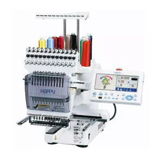
- Page 1 Maintenance Manual for Embroidery Machine (Color Display Additional Manual) HCS-1201-30 Version 1.0 HAPPY Industrial Corporation...
-
Page 2: For Safe Adjustment And Repair
# For safe adjustment and repair # In order to conduct adjustment and repair safely and surely, please be sure to abide by what is mentioned in this manual to prevent trouble. 1. When you conduct adjustment and repair of this embroidery machine or handle electric related parts, you are required to take technical lesson in advance. -
Page 3: Table Of Contents
Index page cover For safe adjustment and repair Index 1 Parts Replacement in control panel and setting 1-1 Open and remove front panel from control box 1-1-1 Open the front panel on the control box 1-1-2 Remove ATA LCD board 1-2 Dip switch setting for ATA LCD board 2 Initialization of system 2-1 Notice for update and Initialize machine systems... -
Page 4: Parts Replacement In Control Panel And Setting
1 Parts Replacement in control panel and setting 1-1 Open and remove front panel from control box 1-1-1 Open the front panel on the control box 1-1-2 Remove ATA LCD board 1-2 Dip switch setting for ATA LCD board... -
Page 5: Cover
Open and remove front panel from control box Open the front panel on the control box 1-1-1 <Check> Please check down machine power completely. 3. Disconnect Inverter power cable. 1. Remove four setscrews behind of control panel Inverter power cable 4 set screws 4. -
Page 6: Remove Ata Lcd Board
Open and remove front panel from control box Remove ATA LCD board 1-1-2 1. Disconnect emergency SW cable Emergency SW cable 2. Disconnect DISP cable. (Please off stopper first) DISP cable 3. Remove ATA LCD board Remove four setscrews Four setscrews Finish of procedures... -
Page 7: Dip Switch Setting For Ata Lcd Board
Dip switch setting for ATA LCD board 1 ------ON Initialize back up data OFF. Non Initialize(Regular) 2 ------OFF. Regular 3 ------OFF. Regular 4 ------ON 5 ------ON Regular Color LCD Size 6 ------OFF. 7 ------OFF. Regular External 8 ------OFF. 9 -----OFF. Regular 10 ---OFF. -
Page 8: Initialization Of System
2 Initialization of system 2-1 Notice for update and Initialize machine systems 2-2 Operation order for update and Initialize machine systems 2-3 Detail operation order for update machine systems 2-3-1 How to Update Program for Control of ATA LCD Board 2-3-2 How to Change Language Setting 2-3-3 How to Update CPU Board Program (from EP-ROM) 2-3-4 How to Update CPU Board Program (from CF card) -
Page 9: Notice For Update And Initialize Machine Systems
Notice for update and Initialize machine systems * Please install program when update (Machine system program, Internal Monogram data) and Replace circuit board (CPU board, ATA LCD board) and indication language. * Contents of system program for HCD are as follows: CPU Board : HCS/H **** (program for control of CPU board ) Letter... -
Page 10: Operation Order For Update And Initialize Machine Systems
Operation order for update and Initialize machine systems * Work sequence of Updating Program are described below. If you need more detail information fro each sequence, please reference each manual 1. Insert CF card saved update program to slot of control panel. Press and keep [MENU] button and turn on the machine 2. -
Page 11: How To Update Program For Control Of Ata Lcd Board
How to Update Program for Control of ATA LCD Board 2-3-1 1. Update of ATA LCD board program 5. Display comes as below after reading data in CF card Insert CF card contains data for version up into CF card [Maintenance] insertion slot [ Install mode ]... -
Page 12: How To Change Language Setting
How to Change Language Setting 2-3-2 1. Change language of LCD panel 5. Select your language and press SET button. Start install Insert CF card included language data to card slot of automatically. control panel. Refer to “ 3-1 How to enter maintenance [Maintenance] mode”... -
Page 13: How To Update Cpu Board Program (From Ep-Rom)
How to Update CPU Board Program (from EP-ROM) 2-3-3 1. Update of CPU board program <Judgment by circuit board itself> Insert ROM in socket with power off Lighting condition of LED4 on the CPU Board enables you to distinguish the result. Control-program [HCS/H **.**] Normal complete : 8times blinking --- lighting... -
Page 14: How To Update Cpu Board Program (From Cf Card)
How to Update CPU Board Program (from CF card) 2-3-4 1. Update of CPU board program 5. .Display comes as below after reading data in CF card Insert CF card contains data for version up into CF card [Maintenance] insertion slot [ Program install ] 2. -
Page 15: How To Update Internal Monogramming Data
How to Update Internal Monogramming Data 2-3-5 1. Update for Internal Monogram data. 5. Press SET button for start update of monogram data. Insert CF card saved update data. Refer to “ 3-1 How to <NOTE> enter maintenance mode” and enter maintenance mode. Please do not take out CF card during installation Display comes as below. -
Page 16: Initialization Cpu Board Memory
Initialization of memory At time of start-up, this is to initialize work memory to specified value. Initialization takes place Initialize “ work memory” . Please practice when you have problem example, strange display, strange machine working. After initialize “ working memory” , Please set machine speed and needle position setting. Initialization ATA LCD board memory 2-4-1 1. -
Page 17: Setting Of Revolution
Setting of Revolution Setting of revolution of main shaft, which is suitable to the machine is required. 5. Main shaft adjusts its revolution speed automatically. If setting is not done, the revolution may not speed up. Message complete will be displayed when setting is finished and it goes back to drive mode. -
Page 18: Setting To Detect Needle Position (For 12 Needles)
Setting to detect needle position (for 12 needles) It is necessary to store value of needle selection sensor 4. Press button and select “ D ” then press SET according to number of needles. If this setting is not made, button. - Page 19 Setting to detect needle position (for 12 needles) 6 Press button and select “ E ” then press SET 9. Press SET button for return to top menu of maintenance button. Memory 12th needle position to machine. mode. [Maintenance] [Maintenance] >...
-
Page 20: Maintenance Mode
3 Maintenance mode 3-1 How to enter Maintenance mode 3-2 Machine Machine movement 3-3 Memory Memory (Machine and Design) check and all erase 3-4 Record Opereration data display 3-4-1 Thread Pattern Number of thread brake times in relation to pattern data 3-4-2 Thread Needle Accumulated total of thread break of a needle 3-4-3 Error Error occurred and the accrual date... -
Page 21: How To Enter Maintenance Mode
Maintenance mode We have 7 maintenance modes as mentioned below Machine Motion of machine Angle Display of machine angle (No use for basic maintenance service.) Memory Check memory and clear all memory Display Switch over the display mode of LCD(Normally not used at maintenance)[1 fixation] Install Update of Control program Installation of Displayed language data Record... -
Page 22: Machine Machine Movement
Machine Machine movement Automatic operation is conducted as bellow. Actuator like a motor might operate according to the contents. During the 3. Press to select desired number to be confirmed operation, it is danger, so keep away your face and hand from and press SET Button [ # ] mark will be displayed left side of desired number to be Machine... -
Page 23: Memory Memory (Machine And Design) Check And All Erase
Memory Memory (Machine and Design) check and all erase Delete all the design memory with checking movement of design memory area. After this process, turn off the power. When you restart the machine, [ E-120 ] is displayed. Press SET Button, turn off the power and turn on again. - Page 24 Record Operation data display Enable to confirm past record of operation Record Thread Pattern Number of stitch of thread break at 30places in the past Needle Accumulated total of thread break of a needle Error Error and date that had occurred in the past 32 cases Thread Pattern Number of stitch of thread break...
-
Page 25: Thread Needle Accumulated Total Of Thread Break Of A Needle
Thread Needle Accumulated total of thread break of a needle 3-4-2 1. Refer to “ 3-1 How to enter maintenance mode” and enter 5. You can check the accumulated number of thread brake maintenance mode times in relation to needle. [Maintenance] Needle 2. -
Page 26: Error Occurred And The Accrual Date
Error occurred and the accrual date 3-4-3 1. Refer to “ 3-1 How to enter maintenance mode” and enter * Enable to Clear Error Record by selecting OK and maintenance mode pressing SET button and return to display of Procedure 4. * If you prefer not to clear it, Select CANCEL and press SET 2. -
Page 27: Setup Machine Setting
Setup Machine setting Basic machine setting will be done. All the setting will be written into built-in Flash Memory card and setting contents will not be deleted even if you proceed all memory clear Be sure to confirm us when you modify below setting contents Contents Number of heads. -
Page 28: Electric System Diagram(Color Display)
4 Electric system diagram(Color Display) 4-1 Electrical connection diagram 4-2 List of electrical connection diagrams... -
Page 29: Electrical Connection Diagram
Electrical connection diagram... -
Page 30: List Of Electrical Connection Diagrams
List of electrical connection diagrams...
Need help?
Do you have a question about the HK634020XB and is the answer not in the manual?
Questions and answers