Advertisement
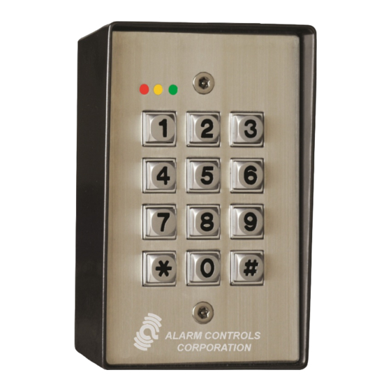
WEATHERPROOF DIGITAL KEYPAD
Model KP-400 is a self-contained vandal resistant digital keypad. This dual-relay output keypad is suitable
for residential, industrial, and commercial installations. It is compatible with all electric locking devices. Du-
rable backlit metal keys and a rugged metal housing protect the keypad from harsh environments.
▪
Operates on 12 or 24 Volts AC or DC
▪
Fully Programmable from the Keypad
▪
Backlit Metal Keys
▪
Two Programmable Relay Outputs
▪
Output 1: 100 User Codes, Output 2: 10 User Codes
▪
False Code Lockout
▪
Request to Exit Input, Duress Output
▪
Audible and Visual Key Press
▪
Die Cast Powder Coated Back Box, 302 Stainless Steel Front Plate
▪
Conforms to IP66
▪
Three year Warranty
MODEL KP-400
VANDAL RESISTANT
Alarm Controls
19 Brandywine Drive
Deer Park, New York 11729
(800) 645-5538
www.alarmcontrols.com
Advertisement
Table of Contents

Related Manuals for Alarm Controls Corporation KP-400


Summary of Contents for Alarm Controls Corporation KP-400
- Page 1 VANDAL RESISTANT WEATHERPROOF DIGITAL KEYPAD Model KP-400 is a self-contained vandal resistant digital keypad. This dual-relay output keypad is suitable for residential, industrial, and commercial installations. It is compatible with all electric locking devices. Du- rable backlit metal keys and a rugged metal housing protect the keypad from harsh environments.
- Page 2 MODEL KP-400 VANDAL RESISTANT WEATHERPROOF DIGITAL KEYPAD OPERATING INSTRUCTIONS Model KP-400 is a self-contained vandal resistant digital keypad. This dual-relay output keypad is suitable for residential, industrial, and commercial installations. It is compatible with all electric locking devices. Durable backlit metal keys and a rugged metal housing protect the keypad from harsh environments.
-
Page 3: Installation
INSTALLATION 1. Remove tamper proof screws from the front of the keypad with the provided tool. 2. Pass the wire harness through the opening in the back box. 3. Mount the back box to the door frame or wall. 4. Make all required wiring connections to the terminal blocks. 5. - Page 4 WIRING 12 or 24 AC or DC. AC power can be connected Power Input without observing polarity requirement. Connect DC (12-24V AC/DC) power with polarity as indicated. SPDT dry contacts. Outputs can be programmed for Output 1, Output 2 latching or momentary operation. A normally-open request to exit station can be Egress Input connected to this terminal and ground (-).
-
Page 5: Programming Mode
KEYPAD INITIATION Keypad initiation must be done at the initial turn-on of the keypad. 1. Connect power to the keypad. 2. Put the keypad in Program Mode by entering “0 0 0 0 ”. The keypad will beep twice and the yellow LED will be on and not blinking. 3. -
Page 6: Operation
OPERATION Enter a valid User Code to activate the associated Output. The keypad must be in standby mode (yellow LED blinking). 1. Enter “(User Code) #”. For example, if the User Code is “1234” you would enter “1 2 3 4 #”. DELETING USER CODES 1. - Page 7 DOOR FORCED OPEN ALARM (CONTINUED) To disable the Door Forced Open Alarm feature - 1. Put the keypad in Program Mode by entering the Installer Code followed by the “”. The keypad will beep twice and the yellow LED will be on and not blinking.
- Page 8 KEYPAD SILENT MODE The keypad beeper can be silenced. 1. Put the keypad in Program Mode by entering the Installer Code followed by the “”. The keypad will beep twice and the yellow LED will be on and not blinking. 2.
-
Page 9: Direct Access To Programming (Dap)
DIRECT ACCESS TO PROGRAMMING (DAP) If the Installer Code is forgotten, the Direct Access to Programming (DAP) utility can be used to put the keypad in Programming Mode. 1. Disconnect the power supply from the keypad. 2. Move the DAP jumper from the OFF to the ON position. 3. -
Page 10: Basic Wiring Diagram
BASIC WIRING DIAGRAM Use N/C contact for magnetic locks and fail-safe electric strikes. Use N/O contact for fail-secure electric strikes. The 1N4004 Diode must be used for DC powered electric strike applications. 12 OR 24V AC POWER CAN ONLY AC OR DC BE USED WITH POWER AC POWERED... -
Page 11: Tamper Switch
INTER-LOCK SYSTEM WIRING DIAGRAM 12 OR 24V 12 OR 24V DOOR DOOR AC OR DC AC OR DC CONTACT CONTACT POWER POWER SUPPLY SUPPLY AC POWER AC POWER MAGNETIC LOCK MAGNETIC LOCK CAN ONLY BE USED CAN ONLY BE USED ELECTRIC STRIKE ELECTRIC STRIKE WITH... -
Page 12: Specifications
SPECIFICATIONS Operating Voltage 12 or 24 Volts AC or DC Auto-sensing 100 mA maximum @12VDC Active Current Draw 120 mA maximum @24VDC 10 mA maximum @12VDC Idle Current Draw 22 mA maximum @24VDC Output 1 Contact Rating 5A@28VDC Output 2 Contact Rating 1A@28VDC Output Contact Arrangement Single Pole Double Throw... - Page 13 KP-400 Rev. E 3/14...
Need help?
Do you have a question about the KP-400 and is the answer not in the manual?
Questions and answers