
Related Manuals for Alarm Controls Corporation KP-100A


Summary of Contents for Alarm Controls Corporation KP-100A
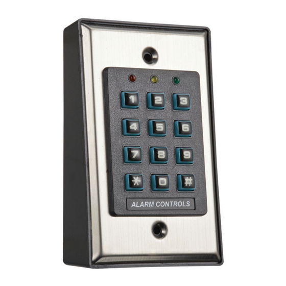
- Page 1 KP-100A BACKLIT DIGITAL KEYPAD FOR ELECTRIC LOCK AND SECURITY SYSTEM INSTALLATIONS Alarm Controls 10027 S. 51st Street, Ste. 102 Phoenix, AZ 85044 800.0645.5538 ASSA ABLOY, the global leader alarmcontrols.com in door opening solutions...
-
Page 2: Table Of Contents
TABLE OF CONTENTS INTRODUCTION ······································································································································· 3 SPECIFICATIONS ···································································································································· 4 INSTALLATION ········································································································································ 5 Precautions ············································································································································ 5 CONNECTION TERMINALS ···················································································································· 6 LED INDICATORS & KEYSTROKE ECHO TONES ·················································································· 7 On-Board LED Indicators ························································································································· 7 Keystroke Echo Tone & The LED Signals ································································································ 7 PREPARATION FOR PROGRAMMING ································································································... -
Page 3: Introduction
INTRODUCTION KP-100A is a self-contained digital access control keypad mainly designed for controlling an electric door lock. It can be either flush mounted on a single gang box or surface mounted on its plastic mounting box. The keypad is ideal for access control and alarm system arm-disarm control. It is also a programmable industrial timer (from 1 second to over 24 hours) for automatic door operator system. -
Page 4: Specifications
SPECIFICATIONS Operating Voltage: 12-24V AC/DC Operating Current: 40mA (quiescent) to 70mA Operation Temperature: -20 C to +70 C Environmental Humidity: 5-95% relative humidity non-condensing Working Environment: Indoor use only Number of Users: Output 1 – 1,000 Number of Visitor Codes: 50, programmable for one time or with the time limit Timing for Code Entry: 10 seconds waiting for next digit entry... -
Page 5: Installation
INSTALLATION ASSEMBLY KP-100A AMBER GREEN FIXING SCREWS X 2 PRECAUTIONS Prevent Accidental Short Circuit: In the previous experience, most of the damages caused in the installation are accidental touching of the components on circuit board with the wires carrying power. Please be patient to study the manual to become familiar with the specifications of the system before starting the installations. -
Page 6: Connection Terminals
CONNECTION TERMINALS CONNECTION TERMINALS TAMPER OUTPUT 1 N.C. N.C. COM. N.O. 1 - 2 : TAMPER N.C. (Tamper Switch Normally Closed Contact) A normally closed dry contact while the keypad is secured on its box. It is open while keypad is separated from the box. -
Page 7: Led Indicators & Keystroke Echo Tones
LED INDICATORS & KEYSTROKE ECHO TONES ON-BOARD LED INDICATORS GREEN (Right) It lights up in Green for Output relay activation It flashes in Standby. It shows the system status in synchronization with the AMBER (Center) --- echo tones. The standby flashing can be turned OFF with programming. See Function 73 (Page 22) for the details. -
Page 8: Preparation For Programming
PREPARATION FOR PROGRAMMING A) CRITERIA FOR CODES Prime Codes a) User Codes b) Master Code c) Supervisor Code d) Visitor Codes All these codes MUST be unique. It is not allowed to repeat a prime code for second function. All the codes in this system can be 4-8 digits for Manual Entry Mode. The codes must be in the same digit length as the Master Code for Auto Entry Mode. -
Page 9: Programming And Operation
PROGRAMMING & OPERATION POWER-UP THE KEYPAD The keypad gives power-up delay of 1 minute after power has been applied. It is the time frame designed for setting the keypad to programming mode with DAP code. See the details of “DAP CODE –... -
Page 10: Direct Access To Programming Mode With The "Dap" Code - 2 8 2 8
DIRECT ACCESS TO PROGRAMMING MODE WITH “DAP” CODE -- 2 8 2 8 In case the Master Code is forgotten, apply the following procedures precisely to set keypad into programming mode with DAP code: Switch OFF all the power for 1 minute to ensure that the keypad is fully discharged. Switch ON power again. -
Page 11: The Default Values Of The Keypad
THE DEFAULT VALUES AFTER REFRESHING FUNCTION PARAMETERS DEFAULT FUNCTIONS & VALUES Master Code 0 0 0 0 Factory Set, Not a default value * Supervisor Code Nil ----- User Program Required User Codes for O/P 1 Nil ----- User Program Required Visitor Codes Nil ----- User Program Required O/P Mode of The O/P 1... -
Page 12: Master Code
MASTER CODE (Function 01) FUNCTION MASTER CODE VALIDATION 4 to 8 Digits (1) FUNCTION Key in Location (2) MASTER CODE Master Code is the authorization code for setting the system to programming mode. It will not operate the output relay like an User Code. The Master Code can be 4 to 8 digits. -
Page 13: Operation And Functions Of The Supervisor Code
OPERATION AND FUNCTIONS OF THE SUPERVISOR CODE 1) Operate Relay Output Supervisor The operation of the Supervisor Code is just like a normal User Code. Simply key-in the Code with number 1 for the relay output. The Supervisor Code can also be used to reset an operating output timer instantly. - Page 14 4) Lockout All The User Codes for Output Relay (Disable Access Control Manually) To enhance the security of the access control keypad, the owner can disable the keypad after office hours, etc. The Output (for door lock control) is inhibited, all the User Codes for it become invalid and those people holding a User Code are refused.
-
Page 15: User Codes - How To Add Or Delete
USER CODES FOR OUTPUT RELAY (Function 10) Total 1,000 User Codes are available for controlling the output relay. Enter programming Mode by entering Master Code and * * FUNCTION MEDIA USER ADDRESS USER CODE VALIDATION (1) FUNCTION – Group 1 – 1,000 User Codes for controlling Output 1 (2) MEDIA (Operation Media) –... - Page 16 1) Example 1 -- Enroll An User Code: i) Programming : (a) The User Code is programmed for operating Output 1 (b) The operation medium is Private User Code only (c) Take ID number 001 in Group 1 to store the User Code, which is one of the IDs in 000-999. Total 1,000 user codes be enrolled.
-
Page 17: Visitor Codes
VISITOR CODES FOR OUTPUT 1 (Function 40) The Visitor Codes are temporary user codes for Output 1 (mainly for door strike in access control). They can be programmed as “One Time Codes” or “Codes with Time Limit”. The Visitor Codes will be cleared automatically after use if they are one time codes, or, when the allowed time expires. - Page 18 EXAMPLES: Example 1: Set a “One Time Visitor Code” with the number of “1 2 6 8” for the Output 1 (a) Visitor Code Programming, (b) The Visitor ID, (c) An One Time Code, (d) The Visitor Code, (e) Entry Confirmation Example 2: Set a “Visitor Code”...
-
Page 19: Output Modes & Timing
OUTPUT MODE & TIMING FOR OUTPUT 1 (Function 51) Enter Programming Mode by entering Program Code and * * The keypad output is programmable for Start/Stop or Timing modes. Apart from door access control, alarm arm-disarm control, there is also an universal timers for automatic operators with up to 99,999 seconds (over 24 hours) of programmable unlock time. -
Page 20: Personal Safety And System Lock-Out
PERSONAL SAFETY AND SYSTEM LOCK-UP (Function 60) Enter Programming Mode by Entering Program Code and * * FUNCTION LOCK-UP OPTIONS VALIDATION 1 to 2 Digits (1)FUNCTION Key in Funtion (2) LOCK-UP OPTIONS The Options are represented by the following Numbers. They are described below: --- After 10 successive false User Code trials, the keypad locks for 60 seconds. -
Page 21: User Code Entry Mode - Auto Or Manual
USER CODE ENTRY MODE – Auto or Manual (Function 70) Enter Programming Mode by entering Program Code and * * FUNCTION ENTRY MODES VALIDATION (1) FUNCTION Key in Function (2) USER CODE ENTRY MODES Two modes 1 and 2 are available for User Code entry options. --- Auto Entry Mode Auto Entry Mode requires no pressing of the # key after code entry for code checking. -
Page 22: Relay Output Operation Announcer
RELAY OUTPUT OPERATION ANNOUNCER (Function 72) Enter programming mode by entering Program Code and * * (1) FUNCTION FUNCTION FUNCTION MODES VALIDATION Key in Function (2) FUNCTION MODES FOR OUTPUT ANNOUNCER Output announcer gives notification Echo Tone on the operation status of the output relay. There are two notification modes available for the selection. -
Page 23: Intelligent Egress Button - An Unique Feature Of A Contemporary Keypad
INTELLIGENT EGRESS BUTTON – AN UNIQUE FEATURE OF THE KEYPAD INTRODUCTION Most of the keypads for access control are just for controlling “Entry” from the outside. It is not enough for today’s access control systems. In fact, controlling “Exit” is also very important in some public passage areas that are not allowed to use locks or digital keypads that prohibit “Exit”... - Page 24 High Traffic Passage: A short buffer time may be necessary for opening a door outward after pressing the egress button for those exits open to a high traffic passage. An egress button with short delay and warning Echo Tones helps the user to pay attention to the people passing by to prevent hitting them when the door is pushed outward.
-
Page 25: Egress Delay , Warning And Alarm
EGRESS DELAY , WARNING AND ALARM (Function 90) Enter programming mode by entering Program code and * * DELAY TIME FUNCTION CONFIGURATIONS VALIDATION (1) FUNCTION Key in Function (2) CONFIGURATIONS OF THE EGRESS WARNING AND ALARM Key in the number to enable 1 of the configurations described below: --- Momentary Contact Mode without Warning -- (Default) Press the Button once. - Page 26 NOTE: 1) Momentary Contact -- The Egress Delay starts to count when the egress button is momentarily pressed. Output 1 activates automatically (door is released) when the delay time is reached. Holding Contact -- The user MUST hold the egress button in contact for the whole period of the Egress Delay time until Output 1 activates.
-
Page 27: Close Programming Mode
CLOSE PROGRAMMING MODE ( * * ) Always close programming mode with * * to set system back to normal Operation after programming. VALIDATION ------------------------------- System is back to normal operation mode... -
Page 28: Programming Summary Chart
PROGRAMMING SUMMARY CHART FACTORY ENTRY LIMITS & CODE DESCRIPTION CODE ENTRY FUNCTION OPTIONS DEFAULT Master Code 4-8 Digits MASTER CODE Supervisor Code 4-8 Digits SUPERVISOR CODE CODE 1 - MEDIA: 2---Add User Code 5---Delete User Code User Code s for O/P 1 CODE1 CODE2 CODE3... - Page 29 STANDARD PROGRAMMING SYSTEM OPERATION CODE ENTRY RESULTS CODES Factory Set Master Code for User to set 0000 * * system in programming Mode at the first time. System in 0 0 0 0 THIS IS NOT A PERMANENT SYSTEM Programming Mode NEW MASTER CODE CODE &...
-
Page 30: Application Example
APPLICATION EXAMPLE STAND ALONE DOOR LOCK WITH ELECTRIC STRIKE KP-100A ELECTRIC STRIKE NOTE: Connect the 1N4004 as close as possible to the strike in parallel with the Electric Strike power terminals to absorb the counter EMF to prevent it from damaging the keypad. -
Page 31: Basic Wiring
1) BASIC WIRING OF A MAGNETIC LOCK KP-100A T1 T2 T3 T4 T5 T6 T7 T8 TAMPER OUTPUT 1 12-24v AC/DC N.C. N.O. **12-24VDC Power Timed Supply Relay Momentary IN4004 Switch Diode Cathode * Magnetic Lock WHITE ALARM CONTROLS TS-2-2T... - Page 32 DOCD0030_1...
Need help?
Do you have a question about the KP-100A and is the answer not in the manual?
Questions and answers