Prolon T1100 User Manual
Digital thermostat prolon t1100
Hide thumbs
Also See for T1100:
- Hardware manual (25 pages) ,
- Quick start manual (14 pages) ,
- Technical reference manual (98 pages)
Table of Contents
Advertisement
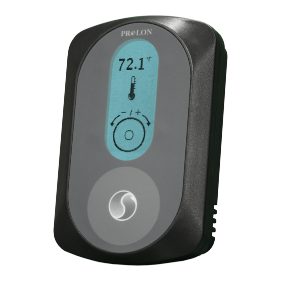
Introduction
The
T1100
digital
thermostats designed for zoning applications. Proportional and integral (PI)
control loops, working in conjunction with fully customizable outputs (1 analog / 1
digital) deliver accurate yet flexible control strategies. An auxiliary analog input is
available for zone temperature averaging or as a radiant floor slab temperature
input. Configuration, performed via a capacitive circular touch pad, is made easy
through an intuitive menu system displayed on a backlit graphic LCD screen.
Installation
1. Open casing to remove back cover by
pushing on the tab located underneath the
thermostat. (Figure 1)
2. Pull wire(s) through central hole of back
cover.
3. Screw in the back cover to the wall.
4. Connect wires:
Pull out the screw terminal blocks.
Remove 1 cm insulation from the end of
each wire.
Connect the wires to the terminal
blocks: see Figure 2 for pin
identification. Typical wiring examples
can be found below.
Reinstall terminal blocks.
5. Reconnect top cover
Important: Do not install the thermostat under
the following conditions:
x Any location exposed to direct sunlight
x On an outside wall
x Near an air discharge grill
x In a location where vertical air circulation
is restricted
x Near a dimmer switch
thermostats
are
networkable,
microprocessor-based
T1100
User Guide
Ver. 5.1
Figure 1
Figure 2
1
Advertisement
Table of Contents

Related Manuals for Prolon T1100


Summary of Contents for Prolon T1100
- Page 1 T1100 User Guide Ver. 5.1 Introduction T1100 digital thermostats networkable, microprocessor-based thermostats designed for zoning applications. Proportional and integral (PI) control loops, working in conjunction with fully customizable outputs (1 analog / 1 digital) deliver accurate yet flexible control strategies. An auxiliary analog input is available for zone temperature averaging or as a radiant floor slab temperature input.
-
Page 2: Network Setup
Power source The T1100 is powered by a 24 VAC power source connected using the "COM" pin and the "24 AC" pin (see 24Vac 120Vac 24 VAC Figure 3). The common for the power source is shared by the auxiliary analog input and the analog output. - Page 3 Figure 6). Outputs Specifications The T1100 series thermostats contain a fully customizable Triac output and a 0- 10VDC output to drive components. An integrated resettable fuse protects both outputs of the T1100 against current surges and short circuits. This protection will cut the current to the output as soon as an overload condition is detected.
- Page 4 Typical wiring of the Digital Output The T1100 opens and closes a triac contact to allow an external source to power the load. External 24 VAC External Load Figure 8: Typical wiring of digital output Typical Wiring of the Analog Output The T1100 provides the control signal to the load, which is powered externally or from the same power source as the T1100.
- Page 5 The touch pad uses capacitive sensing technology to detect finger proximity. There are no moving parts to push or rotate. The T1100 is Tap here to Tap here to controlled using simple scrolling, tapping...
- Page 6 Schedule Override Navigating Menus...
- Page 7 Menu Maps Visualisation and Options Menu Map Configuration Menu Map...
- Page 8 Temperature Menu Map Outputs Menu Map...
- Page 9 Radiant Floor Menu Map Network Menu Map Visualisation Screen...
- Page 10 Menu Guide Section Description Default Units 1.1) Temp Unit Lets select between Celsius Celsius Fahrenheit temperature display. 1.2) Temp Lets you decide how the zone temperature Internal Source is determined: • Internal (Only the onboard thermistor is used to calculate temperature) •...
- Page 11 Section Description Default Units 2.2) Software current software version Vers thermostat device type. 2.3) Hardware Physical version of the thermostat. Vers 2.4) My Address This option lets you set the address of the thermostat on the network. Each device on a network must have a different address.
- Page 12 Section Description Default Units 4.4) Heat Int Defines the amount of time required for the heating integral component of the demand to equalize the proportional component. Setting this value to zero removes the cooling integral component of the demand. 5.1) Heat SP During occupied mode, the thermostat will °C use this value as a low limit for the heating...
- Page 13 Section Description Default Units 7.1) SP Mode Sets the digital output in heating or cooling HEAT mode. 7.2) Setpoint The desired setpoint for the digital output. Cannot be zero. 7.3)Ctrl Mode Sets the digital output in proportional or DIFF differential mode. •...
- Page 14 Section Description Default Units 8.1) SP Mode Sets the analog output in heating or cooling HEAT mode. 8.2) Setpoint The desired setpoint for the analog output. Cannot be zero. 8.3) Ctrl Mode Sets the analog output in proportional or PROP differential mode.
- Page 15 Section Description Default Units 8.8) Range The analog output can be set to work over 0-10V different voltage ranges: • 0-10VDC • 2-10VDC • 0-5VDC 8.9) Override This option lets you manually override the AUTO analog output or set it back to automatic control.
- Page 16 Section Description Default Units 12.1) °C Proportional °F The output pulses at 50% of the cycle length when the slab temperature reaches the setpoint. The proportional band will increase or reduce the length of the pulse depending on the offset from the setpoint. 12.2) Integral Defined as the amount of time required to cause the pulse width to vary by 100% to...
- Page 17 Section Description Default Units 14.4) GrpWght1 The weight of the thermostat in the group selected in GrpCode1. 14.5) GrpWght2 The weight of the thermostat in the group selected in GrpCode2. 14.6) GrpWght3 The weight of the thermostat in the group selected in GrpCode3.
-
Page 18: Specifications
No part of this document may be photocopied or reproduced by any means, or translated to another language without prior written consent of ProLon. All specifications are nominal and may change as design improvements are introduced. ProLon shall not be liable for damages resulting...
Need help?
Do you have a question about the T1100 and is the answer not in the manual?
Questions and answers