
Related Manuals for TYM T254NC


Summary of Contents for TYM T254NC
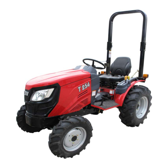
- Page 1 OPERATOR’S MANUAL TRACTORS T254NC DaeYong B/D, 7, Eonju-ro 133-gil, Gangnam-gu, Seoul, Korea ■ TEL: 82-2-3014-2800, FAX:82-2-3014-2852 ■ www.tym.co.kr...
- Page 2 YANMAR WARRANTIES YANMAR LIMITED WARRANTY What is Covered by this Warranty? YANMAR warrants to the original retail purchaser that a new YANMAR TNV common rail series industrial engine will be free from defects in material and/or workmanship for the duration of the warranty period. Note: YANMAR engines may be equipped with external components including, but not limited to: wiring harnesses, electrical devices, control panels, radiator, air filters, fuel/or exhaust systems that are supplied and/or installed by manufacturers other than YANMAR.
- Page 3 YANMAR limited warranty- continued What the Engine Owner must Do: If you believe your YANMAR engine has experienced a failure due to a defect in material and/or workmanship, your must contact an authorized YANMAR industrial engine dealer or distributor within thirty (30) Days of discovering the failure, You must provide proof of ownership of the engine, proof of the date of the engine purchase and delivery, and documentation of the engine operation hours.
- Page 4 YANMAR limited warranty- continued What is no Covered by this Warranty? This warranty does not cover parts affected by or damaged by ant reason other than defective materials or workmanship, including, bur not limited to, accident, misuse, abuse, “Acts of God,” neglect, improper installation, improper maintenance, improper storage, the use of unsuitable attachments or parts, the use of contaminated fuels, the use of fuels, oils, lubricants, or fluids other than those recommended in your YANMAR Operation Manual, unauthorized alterations or modifications, ordinary wear and tear, and rust or...
- Page 5 EMISSION SYSTEM WARRANTY YANMAR CO., LTD. LIMITED EMISSION CONTROL SYSTEM WARRANTY – USA ONLY Your Warranty Rights and Obligations: ■ California The California Air Resources Board (CARB), the Environmental Protection Agency (EPA) and YANMAR Co,. Ltd. hereafter referred to as YANMAR, are pleased to explain the emission control system warranty on your industrial compression-ignition engine.
- Page 6 Limited emission control system warranty – USA only – continued Warranty Coverage: This warranty is transferable to each subsequent purchaser for the duration of the warranty period. Repair or replacement of any warranted part will be performed at an authorized YANMAR industrial engine dealer or distributor.
- Page 7 Limited emission control system warranty – USA only – continued Exclusions: Failures other than those arising from defects in material and/or workmanship are not covered by this warranty. The warranty does not extend to the following: malfunctions caused by abuse, misuse, improper Adjustment, modification, alteration, tampering, disconnection, improper or inadequate maintenance or use Of non-recommended fuels and lubricating oils;...
- Page 8 FORWARD Thank you very much for purchasing our tractor, which, we are sure, will give you many years of trouble free service. This manual introduces you to the correct manner of operating, maintaining and repairing the tractor to ensure long-term durability. Please ensure the correct operation of the tractor as incorrect operation can cause substantial mechanical damage as well as accidents with associated injuries.
-
Page 9: Table Of Contents
CONTENTS Sr. No. Description Page No. 1. Tractor Identification --------------------------------------------------------------------------------- 2. About this Manual ------------------------------------------------------------------------------------- 3. Introduction & Description --------------------------------------------------------------------------- 11~12 4. Owner Assistance -------------------------------------------------------------------------------------- 5. ROPS (Roll Over Protection Structures) ------------------------------------------------------------ 14~16 6. Safety Instructions, Do’s & Don’ts ----------------------------------------------------------------- 17~29 7. -
Page 10: Tractor Identification
The manufacturer warrants this product and the full details of the warranty are provided on a separate warranty schedule. SERVICE. Service is available from any TYM dealer in the country. PARTS. To obtain spare parts, please contact your nearest dealer and give them the details listed below. -
Page 11: About This Manual
This manual has been prepared to assist you in following/adopting the correct procedure for operating and maintaining your new Tong yang Moolsan CO.,LTD (Here in after refer to TYM) Tractor.. Your tractor has been designed and built to offer maximum performance with good fuel economy and ease of operation under a wide variety of operating conditions. -
Page 12: Introduction & Description
A tractor can also be used as a prime mover as it has a power outlet source, called the Power Take or PTO shaft. This manual complies the operation, maintenance and storage instructions for all models of TYM Diesel tractors. - Page 13 Tractors with IPTO(Independent Power Take Off) are fitted with hydraulic clutch assy. The transmission Gear box has six forward speed & two reverse speeds with a high-low select lever. Presently, TYM tractors are fitted with sliding gear and constant mesh type gears. ■...
-
Page 14: Owner Assistance
OWNER ASSISTANCE We at TYM and your TYM dealer/distributor would like you to be completely satisfied with your investment. Normally any problems with your equipment will be handled by your dealer/distributor’s service departments. If however, you feel that your problem has not been handled to your satisfaction by the local dealer/distributor, we suggest the following: Contact the owner or General Manager of the dealership, explain the problem, and request assistance. - Page 15 The objective of the frame or cab structure is to protect the operator in the event of a roll over and to support the entire weight of the tractor. Each TYM ROPS frame or cab structure, as well as all mounting bases and bolts or other fasteners, is designed and has been tested to meet industry and or government standards.
- Page 16 ► DAMAGE OF THE ROPS If the tractor has rolled over or the ROPS has been damaged (such as striking an overhead object during transport), the ROPS must be replaced to provide the original protection. After an accident, check for damages to 1. ROPS; 2. Seat; and 3. Seat belt & seat mountings. Before you operate the tractor, replace all damaged parts.
- Page 17 How to adjust the seat * Sliding type NOTE: Do not use solvents to clean the seat. Use warm water with a small amount of detergent added. Before operating the tractor it is important to adjust the seat to the most comfortable position and check whether it is properly locked in position.
-
Page 18: Safety Signs
SAFETY INSTRUCTIONS RECOGNIZE SAFETY INFORMATION This symbol means ATTENTION! YOUR SAFETY IS INVOLVED. The message that follows the symbol contains important information about safety. Carefully read the message. SIGNAL WORDS. DANGER A signal word―DANGER, WARNING OR CAUTION―is used with a safety alert symbol. DANGER identifies the most serious hazards. - Page 19 USE OF ROPS AND SEAT BELT The Roll Over Protective Structure (ROPS) has been certified to industry and/or government standards. Any damage or alternation to the ROPS, mounting hardware, or seat belt voids the certification and will reduce or eliminate protection for the operator in the event of a rollover.
- Page 20 HANDLE FUEL SAFELY-AVOID FIRES Handle fuel with care; it is highly flammable. Do not refuel the tractor while smoking or near open flame or sparks. Always stop the engine before refueling the tractor. Always keep your tractor clean of accumulated grease, and debris. Always clean up spilled fuel.
- Page 21 AVOID HIGH-PRESSURE FLUIDS Escaping fluid under pressure can penetrate the skin causing serious injury. Keep hands and body away from pinholes and nozzles, which can eject fluid under high pressure. If any fluid is injected into the skin, consult your doctor immediately. PREVENT BATTERY EXPLOSIONS Keep sparks, lighted matches, and open flame away from the top of the battery.
- Page 22 WORK IN VENTILATED AREA Do not start the tractor in an enclosed building unless the doors and windows are open for proper ventilation, as tractor fumes can cause sickness or death. If it is necessary to run an engine in an enclosed area, remove the exhaust fumes by connecting an exhaust pipe extension.
- Page 23 SAFE OPERATION OF YOUR TRACTOR The manufacturer of your tractor has made every effort to make it as safe as is humanly possible. Beyond this point it is the responsibility of the operator to avoid accidents and we ask that you read and follow our recommendations for your safety.
- Page 24 SAFETY TIPS DURING MAINTENANCE 1. Check all oil levels, water level in the radiator and electrolyte level in the battery at least once a day, and perform services according to the service schedule. 2. Ensure that tire pressures are even and the correct pressure for the job to be performed is maintained. 3.
- Page 25 ► MOUNTING AND DEMOUNTING IMPLEMENTS (1) Ensure that all mounting and removal of implements is done on a safe flat ground. Ensure no one is between the tractor and implement to avoid accidental injuries, do not get under the implement. (2) After mounting the implement, ensure that all sway chains are correctly adjusted and, if a PTO shaft is used, that the shaft is fitted and secured correctly.
- Page 26 ► THE FOLLOWING PRECAUTIONS ARE SUGGESTED TO HELP PREVENT ACCIDENTS. A careful operator is the best operator. Most accidents can be avoided by observing certain precautions . Read and take the following precautions before operating the tractor to prevent accidents. Tractors should be operated only by those who are responsible and properly trained to do so.
- Page 27 Do not bypass the safety starter switch. Consult your TYM Tractor dealer/distributor if the safety starter switch malfunctions. 4. Avoid accidental contact with the gear shifter lever while the engine is running. Unexpected tractor movement can result from such contact.
- Page 28 Driving the tractor ■ 1. Watch where you are going especially at row ends, on roads, around trees and low hanging obstacles. 2. To avoid upsets, drive the tractor with care and at speeds compatible with safety, especially when operating over rough ground, crossing ditches or slopes, and when turning at corners. 3.
- Page 29 DO’S AND DON’T’S ► DO’S-For Better performance DO-Ensure that safety shields are in place and in good condition. DO-Read all operating instructions before commencing to operate the tractor. DO-Carry out all maintenance tasks without fail. DO-Keep the air cleaner clean. DO -Ensure that the correct grade of lubricating oils are used and that they are replenished and changed at the recommended intervals.
- Page 30 DON’T-Use the independent brakes for making turns on the highway or at high speeds. DON’T-Refuel the tractor with the engine running. DON’T-Mount or dismount from the right side of the tractor. DON’T-Tamper the hydraulic control levers’ upper limit stops. DON’T-Use the draft control lever for the lifting of implements. DON’T-Start the engine with the PTO engaged.
- Page 31 SAFETY SIGNS ► GENERAL SAFETY INFORMATION IMPORTANT: This “General safety Information” should be kept with the machine at all times as reference data. This symbol means ATTENTION! YOUR SAFETY IS INVOLVED. The message that follows the symbol contains important information about safety. Follow the recommended precautions and safe operating practice.
- Page 32 DECALS ON THE CHASSIS...
- Page 33 DECALS AROUND THE SEAT...
-
Page 34: Universal Symbols
UNIVERSAL SYMBOLS Some of the universal symbols and their meaning are shown below. Engine Speed Pressured- Corrosive rev/min x 100) open slowly Substance ”Tortoise” Hours, Continuous Slow or recorded Variable Minimum Setting Engine ”Hare” Fast or Coolant Warning Maximum temperature Setting Hazard Transmission... -
Page 35: Controls, Instruments & Operations
It is too late to learn once the tractor has started moving. If in doubt about any aspect of the operation of the tractor, consult your TYM tractor dealer/distributor. Particular attention should be paid to the recommendations for running the tractor to ensure that your... -
Page 36: Hand Throttle Lever
DESCRIPTION OF TRACTOR CONTROLS ► INSTRUMENTS AND SWITCHES Left Turn Signal Lamp Right Turn Signal Lamp Fuel Gauge Tachometer Hazard Warning PTO On/Off Button Turn Signal S/W Hand Throttle Lever Horn S/W Head Lamp S/W Key S/W Parking Brake Lever ►... - Page 37 ► HOUR METER The hour meter consists of digits with the last digit indicating 1/10 of an hour. ► TACHOMETER This meter shows the revolutions of the engine and the PTO shafts as well as the travel speed in top gear. ►...
-
Page 38: Warning Lights
►WARNING LIGHTS CHARGE LAMP This light will go off as soon as the engine starts to run to indicate that the alternator is charging. (Please note that a broken fan belt can cause the light to come on. In this case, stop the engine as overheating can occur if not rectified immediately) OIL PRESSURE LAMP Will go off as soon as the engine starts if the oil pressure is correct. - Page 39 ■ THE PTO MONITOR LAMP On the dash panel indicates the state of the PTO shaft. 1. If the monitor glows: The PTO is rotating. 2. If the monitor is off: The PTO is off. PTO monitor Lamp ■ PTO ON/OFF SWITCH PTO ON/OFF switch is situated on the right hand side on the instrument panel and can be identified easily with its built in yellow colored indicator.
-
Page 40: Throttle Lever
► TRACTOR CONTROLS Parking Brake Lever Steering Wheel Brake Pedal Clutch Pedal Acceleration Pedal 4WD Shift Lever Main Shift Lever Rear / Mid PTO Lever And Reverse Lever Sub Gear Lever Position Lever Throttle Lever ► THROTTLE LEVER (HAND THROTTLE) Pulling the hand towards the driver increases revolutions. - Page 41 ► BRAKE PEDAL Right and left brake pedals are provided to assist in turning the tractor in the field. A connecting latch is provided to connect the right and left brake pedals for high Speed of road use. In the interest of safety always use it on the road or at high speed as using one side Only can cause rollovers.
- Page 42 ► MAIN SHIFT & REVERSE LEVER The Main Shift & Reverse Lever is located on the RHS of the operator. The Main Shift & Reverse Lever provides three forward speeds: 1,2, and 3, N (neutral), and one reverse speed, R, Forward speeds may be changed While the tractor and depress the clutch before changing direction.
- Page 43 ► SUB GEAR LEVER (RANGE SHIFT LEVER) The range shift lever provides two speed ranges L and H. The tractor should be stopped and clutch depressed before changing speed ranges. Choose L, M speed range on range shift lever to match work application. SUB GEAR LEVER SUB GEAR LEVER (RANGE SHIFT LEVER)
- Page 44 Front wheel Driver Lever ► FRONT WHEEL DRIVE LEVER (4WD) (4WD Lever) Front wheel drive lever is located below the LHS of the Operator. In the ON position the front wheels are engaged and in the OFF position they are disengaged. Engage or disengage the front wheel drive with the front wheels in the straight position and at low speed.
- Page 45 Both the rear and mid PTO are provided for variable utility. They can be engaged simultaneously or independently at same time. The engine will not start if the PTO switch is in ON position. The engine will shut off if the operator leaves the seat with parking brake released and the PTO engaged. To avoid damage of transmission and implement, do not engage the PTO with the engine running at high speed.
- Page 46 MID PTO The speed of the mid PTO is 2,000rpm. Use the PTO lever to engage. The PTO switch must be OFF before the PTO is engaged. 1. Decrease the engine speed to near idle. 2. Make sure that the PTO switch is OFF. 3.
- Page 47 ► OPERATING THE HYDRAULICS The hydraulics are powered with an engine driven hydraulic pump and controlled with a position control lever mounted beside the driver. ► HITCH CONTROL LEVER The hitch control lever is used to raise or lower the implement mounted to the three point hitch. To raise the hitch, move the lever to the rear.
- Page 48 Always set the knob to lock when 1.Traveling on the road 2. Replacing tires or blades on an implement. 3. Making adjustments to an implement. The sudden dropping of an implement due to Caution hydraulic problems can cause serious injury or death. ►...
- Page 49 ► ADJUSTMENT OF THE CHECK CHAIN To adjust the check chain, turn the turnbuckle to lengthen or shorten the chain. Tighten the lock nut when the correct adjustment is achieved. Fixing Nut Turn buckle Check chain ► ADJUSTMENT OF THE LIFT ROD Adjust the length of the lift rod by screwing the Adjusting Handle (Turnbuckle) in or adjust the length of the lift rod as necessary to set the implement in its working position parallel to the ground.
- Page 50 ► ADJUSTMENT OF THE YOKE ROD ON THE LOWER LINK For different applications, change the position of the Yoke rod on the lower link holes as shown and insert the pin in the direction of the arrow. Lift Rod Only use the drawbar to tow and keep the three point linkage in the raised position when towing with the drawbar.
- Page 51 DRIVING THE TRACTOR ► STARTING THE ENGINE Before starting the engine carry out the pre-operational checks as set out on page 26. (1) Sit on the driver seat. (2) Apply the footbrake. (3) Put the hydraulic lever in the neutral position. (4) Push down the clutch to activate the safety-starting switch.
- Page 52 ► WARMING UP When starting the engine, allow it to warm up to operating temperature by running it idle for 5-10 minutes to ensure full lubrication and that the engine reaches the operating temperature. Failure to do so can shorten engine life substantially. ►...
- Page 53 ► NORMAL BRAKING AND PARKING Let the engine come back to idle and at the same time push in the clutch and brake simultaneously. When the tractor has come to a halt, lower any implement to the ground, and put the main gear in neutral. Apply the parking brake, stop the engine, and remove the key.
- Page 54 ► CHECK DURING DRIVING Constantly monitor the warning lights on the dash and if any light comes on, stop the tractor to determine the cause. If the oil pressure light comes on, first check the oil level. If the oil level is OK, ask a qualified dealer to check the reason for the light coming on.
-
Page 55: Lubrication & Maintenance
Section-B Lubrication & Maintenance This section gives the full details of the service procedures necessary to maintain your tractor at peak efficiency while the lubrication and maintenance chart provides a ready reference to these requirements. - Page 56 CHECKS AND SERVICE ► PRE-START CHECKS To avoid problems it is recommended that a range of checks be carried out daily before starting the tractor. For full details of the items and frequency please refer to the tables on page 58, 59 and 60. ►...
- Page 57 ► TRANSMISSION OIL Check the level with level gauge on the rear of the transmission. If the level is low, add oil through the filler hole. Always ensure that you use the correct oil for topping off or oil changes Caution ►...
- Page 58 ► STEERING Ensure that the steering wheel does not have excessive free play. ► BRAKE Ensure that the left and right brake rods are adjusted correctly so that they operate simultaneously. The correct free play on the brake is 1.18-1.57 inches (30~40 mm). ►...
- Page 59 MAINTENANCE AND ADJUSTMENT SCHEDULE ○ Check, Top-off or adjust ● Replace ► Periodical check and service table △ Clean or wash ★ Consult the service Dealer Service interval(hour meter,mark) Item Frequency Comment Every 100 hours or To correct ● ● ●...
- Page 60 Service interval (hour meter/mark) Item Frequency Comment Every 500 Trans hours or 12 ○ ● ★ ● mission months after first 50 hours Free play ○ of brake Check daily pedal Operation ○ of each Check daily lever Free play About 50 mm ○...
- Page 61 Service interval(hour meter,mark) Item Frequency Comment Operation of Check ○ daily instrument Adjustment of the ○ ○ throttle pedal Free play of ○ (0.78~1.18in) Clutch pedal Check after every 100hrs . 4WD front Replace Replace if ● ○ ○ ○ ○...
- Page 62 TRANSMISSION CASE See next page * (API GL-4 Grades) Gear oil #80 or #90 FRONT AXLE TYM EP GEAR OIL SAE 80W-90 3.5ℓ (0.92US gal) FINAL DRIVE CASE(B) (API GL-4 Grades) Gear oil #80 or #90 TYM UNIVERSAL TRACTOR FLUID...
- Page 63 ► RECOMMENDED TRANSMISSION OIL ① TYM UNIVERSAL TRACTOR FLUID ► OPENING METHOD OF EACH COVER ► OPENING METHOD OF FAN COVER guide hook lock Pull the lower center lever of the front grille counter clockwise, pull the lower edges of hood panel upward, and pull the whole panel forward until the guide hook lock is hooked to the groove.
- Page 64 Fuel Filter Cock ■ BLEEDING THE FUEL SYSTEM 1. Fuel filter cock 「ON」 ① 2. Open the cock on the fuel injection pump 3. Fill the tank with fuel and turn on the ignition key. 4. Start the engine and allow it to run for a while 5.
-
Page 65: Specifications
Engine Oil Gauge ► CHANGING THE OILS IN THE TRACTOR Always use quality oils for engine or transmission oil. Refer to the table on page 58 and 59 for the change frequency. ► CHANGING ENGINE OIL Park the tractor on a level surface, shut-off the engine and remove the sump plug &... - Page 66 ► CHANGING OIL IN THE FRONT AXLE 1. Drain the oil from the center diff plug and the drain plug in each drive. 2. Replace and tighten all drain plugs. 3. Remove the Fill/Lever plugs from each final drive to vent air from it. 4.
- Page 67 ► ENGINE OIL FILTER CARTRIDGE Remove the filter with a filter wrench. Engine Oil Gauge To replace, apply oil or grease on the seal, fit by hand until the seal contacts, then turn it by a 2/3 turn further to tighten it; check for leaks. Engine Oil Filter ►...
- Page 68 ► ANTI FREEZE Frozen cooling water can damage the engine. Before replacing the anti freeze solution flush the radiator. Mix the anti freeze solution in accordance with the instructions applicable to the brand of anti freeze and the local climate. Replace the solution in the radiator.
- Page 69 ► GAP ADJUSTMENT ► ADJUSTING THE CLUTCH Using the clutch over a period of time will increase the Free play. The correct free play of the pedal is 0.7~1.18in To adjust, loosen the locknut on the turnbuckle and adjust. Check the adjustment and tighten the locknut if the free play is correct.
-
Page 70: Battery Maintenance
Indicator condition ► CHECKING THE BATTERY Check the Indicator Green color – Good condition. Black color – Charging necessary. White color – Replace battery. Low electrolyte levels can cause premature battery failure and corrosion. Important Electrolyte contains acid can cause serious burns. Any spillage on the skin should be washed off with running water immediately. - Page 71 Always disconnect the negative terminal first when removing the battery and always connect the positive terminal first when fitting the battery. When connecting the battery leads, make sure not to reverse the polarity. Quick charging will reduce battery life. Caution Disconnect the terminals prior to charging the battery to avoid damage to the circuit and electrical instruments.
- Page 72 Always check the causes for a blown fuse; otherwise the new fuse is also likely to blow. NEVER EVER USE WIRE in place of a correct grade fuse. Important ► SERVICE PRIOR TO DAILY AND SHORT TERM STORAGE. Wash the tractor and keep it clean. Fill the tank to avoid condensation and rust.
- Page 73 ► CHECKING HOSES AND LINES The fuel lines, radiator hoses, hydraulic and rubber hoses are consumables, which deteriorate by age and use. Check them regularly and replace them if they are faulty. Damaged fuel lines leak and cause fires. Damaged radiator hoses can cause hot water burns, and in severe cases, seize the engine. Caution ►...
- Page 74 MAINTENANCE For daily or short term storage Clean the tractor and remove all dirt from field work. Fill the fuel tank to avoid condensation and rust. Lower the implement to the ground. Keep it in a machinery shed or, if not available, cover the unit if left outside. In very cold conditions, it is advisable to remove the battery and keep it inside in a warm environment.
-
Page 75: Specifications
For further information concerning your tractor and equipment, consult your authorized TYM dealer/distributor. TYM improves its policy continuously and reserves the right to change prices, specifications or equipment at any time without notice. All date given in this book is subject to production variations. - Page 76 SPECIFICATIONS Model: T254NC ENGINE Type : Dry single plate Four strokes, Indirect injection, water-cooled Outer dia. x Inner dia. : 8.86 x 5.9” Diesel Engine. Model : 3TNV80F-SDKTF TRANSMISSION No. of cylinders Type : Constant mesh, Sliding gear Displacement(cc) : 1,267cc No.
- Page 77 MODEL T254NC Maker Yanmar 3TNV80F-SDKTF Model Type Water cooled 4 cycle 3 cylinder diesel Out put (kW/rpm) T254NC – 17.8kw / 3,000 Number of Cylinder 1,267cc Displacement (cc) 80 mm x 84 mm Bore and Stroke 23:1 Compression ratio Engine...
- Page 78 MODEL T254NC Main Dry single disc, mechanic Clutch Multiple wet disk Overall length(mm) 2350 Overall width (mm) 1290 Overall Height (mm) 2278 Wheel base (mm) 1460 (Distance between shafts) Min. Ground Clearance (mm) Front 6-12 6PR Dimensions (W/R3 Tire) Rear 9.5-16 6PR...
- Page 79 Operation Hydraulic Mounting method 3-Point hitch Drawing method Trailer hitch Implement 3-Point hitch category Category 1(N) Hydraulic-control Position * SPEED CHART (KM/H) (Engine Rated RPM) L -1 0.98 0.85 0.81 L -2 1.74 1.51 1.44 L -3 3.04 2.65 2.53 5.33 4.64 4.43...
-
Page 80: Fuel Saving Tips
FUEL SAVING TIPS To save fuel and oil in your tractor, the following measures should always be made. A) Air Cleaning System 1) Clean the air cleaner regularly so that dust does not settle down. 2) For every 50 hours and everyday in sandy: (a) Clean the air cleaner filter element with compressed air. - Page 81 E) Engine system 1) Always use the recommended grade of oil. (API CD:CE) 2) Every day before starting the engine, check the oil level with a dipstick & refill it so that the level of oil sits between minimum and maximum levels. 3) Change the engine oil, replace the filter and “O”...
- Page 82 FAULT TRACKING SYMPTOM CAUSE REMEDY Turning the main switch Clutch not pushed in Push the clutch in will not operate the starter Battery flat Charge or replace the battery Dealer to repair or replace Switch faulty Contact dealer to repair or replace Starter operates but not Low battery...
- Page 83 SYMPTOM CAUSE REMEDY White smoke from the Oil level too high Reduce to correct quantity exhaust Shortage of or faulty fuel Contact dealer for repair Reduced performance of The injectors are clogged, Contact dealer for repair the engine carbon coated and sticking Low compression Leaking valve seat Contact dealer for repair...
- Page 84 SYMPTOM CAUSE REMEDY The clutch slips Incorrect adjustment Adjust to correct free play Worn or burnt lining Contact dealer for repair The clutch does not Incorrect adjustment Adjust to correct free play disengage Rusty clutch lining Contact dealer for repair Brake not working Incorrect free play Adjust to correct free play...
- Page 85 SYMPTOM CAUSE REMEDY Steering wheel shaking Wrong toe-in Adjust toe-in Unequal tire pressure Inflate both to correct pressure Loose component Tighten or replace if worn Excessive play in the Worn steering shaft Contact dealer for repair steering Worn components Contact dealer for repair Flat battery Faulty wiring Repair, reconnect or tighten as...
- Page 86 HARNESS DIAGRAM...
-
Page 87: Wiring Diagram
► Drawing for fixing position of the fuse ► Wiring diagram of the electric instrument * Main Fuse HAZARD COUPLER EG STOP, PTO 7.5A GLOW TIMER LIGHT, HORN ① Head Lamp 12V/ 55W PANEL ② Combination Lamp 12V/ 21W/ 5W TURN SIGNAL ③... -
Page 88: Tractor History Card
TRACTOR HISTORY CARD NATURE OF JOB CARD W/CLAIM NO. DATE PARTS REPLACEMENT REMARKS AND DATE DEFECT... -
Page 89: Service Record
SERVICE RECORD DATE TRACTOR HOURS NATURE/TYPE OF REPAIR/SERVICE CARRIED OUT... - Page 90 DAILY OPERATION LOG MACHINE HOURS FUEL ENGINE OIL DATE REMARKS DONE CONSUMPTION TOPPED UP START...
-
Page 91: Part Replacement Record
PART REPLACEMENT RECORD PART PART DATE Q’TY COST DATE Q’TY COST DESCRIPTION DESCRIPTION... - Page 92 T254NC Operator’s Manual for TYM Tractors Code No. 1113-912-002-0 Printed in June 2014 1st Edition...
Need help?
Do you have a question about the T254NC and is the answer not in the manual?
Questions and answers