Table of Contents
Advertisement
Quick Links
Advertisement
Table of Contents

Related Manuals for Neve Custom Series 75


Summary of Contents for Neve Custom Series 75
- Page 1 revision: 2.2 15 May 2013 5:01 PM Owner’s Manual For Software Version 3...
-
Page 2: Table Of Contents
Contents Introduction Modifications about This Manual Modification 1 - Insert Point Post/Pre eQ Terminology Modification 2 - Installing additional Modules Block Diagrams Quickstart Installation Channel & Input Block Diagram Health & safety Group amps Connections stereo Mix & Outputs Master section rear Panel Cr Monitor Channel Bin rear Panel auX Headphone &... -
Page 3: Introduction
BA338 amplifying stages and legendary BA283 output character or transparency! stages combined with classic Neve LO1166 output The Custom Series 75 is a console that is here to stay. transformers, sound warm, defined and punchy. Stereo busses are implemented in both classic (voltage... -
Page 4: About This Manual
Custom Series 75 console, not to be read cover to cover, Installation: but as an accompaniment helping you to get to know »... -
Page 5: Installation
Installation On the rear panels of the Custom Series 75 you will find the input and output connections on a combination of DB25, TRS and XLR connectors. The wiring diagrams for each connector can be found in the Wiring Diagrams section of this manual. -
Page 6: Master Section Rear Panel
Master section rear Panel 7.1 Input Main Spk Surround Spk (Alt2) 2Trk1 Mon In Reverb (Stereo) Returns Speakers Mix Out Aux Sends model type serial no . Made in Australia SLS, Red Light, TB, Listen WARNING N25549 DISCONNECT PSU LEAD BEFORE REMOVING MODULES Headphones Group Out/Ins Send... - Page 7 speakers Mix Out, 2254 Carries the Main Speaker Outputs, Alt 1 and Monitor There are two separate mix outputs on the Series 75 , Mix Output signals. In an ideal world, the Main Speaker Modern and Retro. See Modern Output Stage and Retro Outputs and Monitor Mix Outputs will be connected to the Output Stage for details.
-
Page 8: Channel Bin Rear Panel
Channel Bin rear Panel DI Inputs Mic Inputs Send Inserts DAW In Line In Direct Out Return line In On the rear panel of each Channel Bin you will find eight balanced Mic Inputs (XLR) and eight DI inputs (1/4"). Daw Inputs and line Inputs are available on DB25 Envisioned connection is the output of external devices connectors. -
Page 9: Operation
Powering up The Power supply and soft start The Custom Series 75 is powered by an external Power Supply, and utilises Soft Start Technology. A large current is needed to power the console. A circuit To ensure a safe power up, observe the following board containing a microchip (known as the soft start procedure. -
Page 10: Retro And Modern Circuitry
There are a few ways in which these the block diagrams. sounds can be achieved, however the true versatility of the Custom Series 75 is realized with the combinations of recording both Retro and Modern circuitry. If you would like to quickly compare the sound of the... - Page 11 ‘Group Out/Ins Send’ DB25’s on the rear panel of the Master Section, or could be made available on a On the 2081 module of the Custom Series 75, selecting patchbay. RETRO assigns the Channel Output to the Voltage Further experimentation Summing Mix Bus.
-
Page 12: The 2081 Module
The 2081 Module Meterbridge N2081 Each inline 2081 Channel Module has two independent paths, CHANNEL path and FADER MAIN SWAP MONITOR path. Multiple inputs can be selected for each path. The Channel path is -10 TRIM 10 controlled by a fader, and the Monitor path +48V is controlled by a rotary. -
Page 13: Input Module
Input Module auxiliaries The Input Module hosts the Each module contains two N2081 Channel Input Selector, Gain stereo (A & B) and three mono AUX B (Aux 1, Aux 2, Aux 3) auxiliary and Trim, Phase, 48V, and sends. The order in which High Pass Filter. -
Page 14: 2081 Eq
2081 eQ Monitor path, Channel Output & retro Based on the acclaimed 1973 - 1081 EQ. In a recording or mixdown environment the The Monitor path section 2081 Channel Module's EQ, features a rotary trim control GAIN LINE blurs the line between circuitry and two selectable inputs, DAW and musicality. -
Page 15: Channel Path Fader
Channel Path Fader The Channel Path Fader feeds the Direct Out. The Destination LEDs situated at the top of each Module (below the Channel Path Meters) will indicate whether the Channel Path Output is also routed to one or more of the eight Groups, or the stereo Bus (via the Retro or Modern bus) - see the Assign Section for routing details. -
Page 16: Master Section
Master section -180 The Master section of the Custom Series 75 is host to two linkable (and externally CLIP CLIP CLIP CLIP CLIP CLIP CLIP CLIP patchable) mono 2254 compressors, the 2081 Channel Module routing options, eight Groups, comprehensive monitoring, Listen Back and Talkback controls, Headphone Sends, and an analog Oscillator. -
Page 17: Metering
Metering -180 CLIP CLIP CLIP CLIP CLIP CLIP CLIP CLIP The Series 75 Master Section features a comprehensive meterbridge. Eight 42 segment Bargraph Meters allow for seamless VU or PPM metering of the Main Mix, Monitor Mix, Auxiliaries, Groups, or Reverb Returns. When in PPM Mode, the top four segments of each bargraph meter will light brighter to indicate the proximity to clipping. -
Page 18: 2254 Compressor Meters
2254 Compressor the Master Section. When the Mix button is N2069 inactive, the 2254 will process the external inputs. IN - Lights yellow when selected. Sends the signal through the units circuitry, even if the unit does not have the Limit or Compress functions selected. -
Page 19: Assign Section
Five preset ratios are provided: 1.5:1, 2:1, 3:1, 4:1 and Any selected Channel(s) can be routed to one or 6:1. more Groups by pressing and holding any one of the Group Buttons 1 - 8. This sums the selected Channel The control characteristic is shaped such that the onset output(s) onto the selected Group Mix Bus, and outputs of compression is smooth and progressive, the true... -
Page 20: Scenes
scenes Custom user Features All recallable buttons on the console can be stored and The following features are aimed at integrating the user's instantly recalled later. These stored settings are called personal workflow with the Series 75 console. scenes. A total of eight Scenes can be stored using buttons 1 - 8. -
Page 21: Oscillator & Sls
Oscillator & sls Oscillator N3673 GRPS PINK MAIN LEVEL OsC - Activates the Oscillator, which in conjunction with the seven position switch can output 40hz, 60hz, 100hz, 1Khz, 10Khz, 16Khz or pink noise. The Studio Loudspeaker (SLS) is an additional speaker GrPs - Routes the Oscillator to the Group Outputs. -
Page 22: Group Send/Returns
Group send/returns The DAW button may act as a Group Insert enable if you have connected Group Out/Ins Send and DAW/Ins Return to and from outboard gear or a patch bay. The output of the eight Groups are available at the Local Mix Bus (which feeds both Retro and Modern Mix Outs), GRP1 GRP2... -
Page 23: Reverb Returns
reverb returns Headphone sends AUX 1 AUX 2 AUX 1 AUX 2 AUX A AUX A HP 2 HP 2 HP 2 HP 2 L BAL R L BAL R L BAL R L BAL R MAIN MAIN AUX 3 AUX B AUX 3 AUX B... -
Page 24: Channel Meters/Master Meters
Channel Meters/ GrP - Meter the Group Outputs: 1, 2, 3, 4, 5, 6, 7, 8. Master Meters auX/PFl - Meter the Auxiliary Master levels and the PFL Outputs: A1, A2, A3, AL, Ar, bL, br, PF. reV reT - Meter the four stereo Reverb Returns: 1L, 1r, CHANNEL METERS 2L, 2r, 3L, 3r, 4L, 4r. - Page 25 reTrO - Routes the Channel path to the Channel retro Output stage or Channel Modern Output stage before they join either the Voltage summing or Current summing Bus respectively. Keep in mind that the above functions can also be changed on a per Channel basis in the Channel/Monitor Modules section.
-
Page 26: Control Room
Control room Source section in combination with ALT2 routes the 7.1 Input to the ALT2 Speaker Outputs. The high fidelity Control Room monitoring circuitry allows lCuT & rCuT - These cut the left and right channels for sonically transparent monitoring of up to 12 sources. of the currently selected Speaker Outputs. -
Page 27: Control Room Headphones
Control Room section) to the selected Speaker Outputs Outputs. The AFL bus is stereo, and soloing via the Main Volume control. is non-destructive (solo does not affect the Channel Direct Output or Main Mix Out signals). suM - Is a latching function, and allows multiple Monitor Sources to be selected. -
Page 28: Faders
This prevents any destructive functions from effecting the Main Mix Output or Channel Direct Outputs. reD lIGHT - Completes the isolated voltage circuit required to activate a red light if connected. Red Light also engages Status Lock to prevent the Main Mix Output or Channel Direct Outputs from being affected. -
Page 29: Modifications
Modifications 7. If all three jumpers are placed on the two pins closest to the Channel Bin Motherboard, the Insert will fall pre-EQ. There are two modifications that, depending on your workflow, you may like to make. 8. Once the changes have been made, replace the Module carefully and firmly Insert Points on each 2081 Module default post-EQ. -
Page 30: Block Diagrams
Block Diagrams Channel & Input Block Diagram... -
Page 31: Group Amps
Group amps... -
Page 32: Stereo Mix & Outputs
stereo Mix & Outputs... -
Page 33: Cr Monitor
Cr Monitor... -
Page 34: Aux Headphone & Stereo Returns
auX Headphone & stereo returns... -
Page 35: Ancillary
ancillary... -
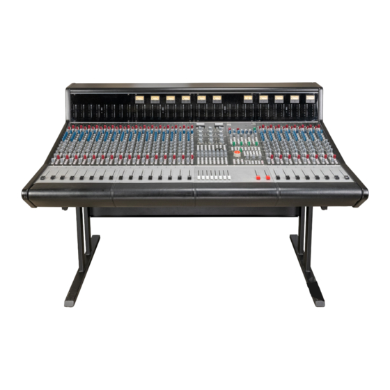
Page 36: Dimensions
Dimensions a: 45cm b: 99cm c: 30.7cm d: 70.5cm e: 12cm » 32 Channel Frame Width: 167cm (65.75 in) » Depth: 99cm (38.98 in) » Height (without stand): 45cm (17.72 in) » 24 Channel Frame Width: 135cm (53.15 in) » Depth: 99cm (38.98 in) »... -
Page 37: Recall Sheets
The following pages contain printable Recall sheets for the Custom Series 75. - Page 38 session: Date: Notes: 800mS 1.5S 400mS AUTO GRPS PINK MAIN LEVEL COMP IN COMP THRESHOLD GAIN MAKE UP COMP RECOVERY 200mS 800mS 100mS AUTO 1.5:1 AUX2 AUX SEND TRIMS LIMIT ON FAST ATTACK 2254 HP 2 HP 2 HP 2 HP 2 LIMIT LEVEL LIMIT RECOVERY...
- Page 39 session: Date: Notes: -10 TRIM 10 -10 TRIM 10 -10 TRIM 10 -10 TRIM 10 -10 TRIM 10 -10 TRIM 10 -10 TRIM 10 -10 TRIM 10 +48V +48V +48V +48V +48V +48V +48V +48V MIC/DI GAIN MIC/DI GAIN MIC/DI GAIN MIC/DI GAIN MIC/DI GAIN MIC/DI GAIN...
-
Page 40: Wiring Diagrams
wiring Diagrams Xlr Connectors Shield Cold (-) Hot (+) Shield Cold (-) Hot (+) Hot (+) Cold (-) Shield 1/4” Trs & Ts Sleeve Ring Sleeve Tip Connectors DB25 Connectors All DB25 connectors are wired with Tascam pinout & numbering, housing screws are imperial thread. Each Channel Bin uses DB25 for Direct Out, Line In, DAW In, Insert Send &... -
Page 41: Master Section Rear Panel
Master section rear Panel 7.1 Inputs surround spk (alt2) Naturally, the following labels are just a guide. Labels As mentioned previously, the following labels are just have not been added to the console, maintaining a guide. Labels have not been added to the console, consistency between the 7.1 input wiring and maintaining consistency between the 7.1 input wiring the Surround Spk (Alt2) output wiring is the main... -
Page 42: Reverb (Stereo) Returns
reverb (stereo) returns aux sends Pin # Connection Cable # Pin # Connection Cable # Ret+4R Osc+ Ret-4R Osc- Ret+4L AUX Out BR+ Ret-4L AUX Out BR- Ret+3R AUX Out BL+ Ret-3R AUX Out BL- Ret+3L AUX Out AR+ Ret-3L AUX Out AR- Ret+2R AUX Out AL+... -
Page 43: Headphones
Headphones Mix Outs & 2254 Pin # Connection Cable # Note: Unbalanced outputs are able to drive up to 10 2254 In R+ headphones without the need for an external headphone 2254 In R- amp, the balanced outputs will need to be connected to a headphone amp. -
Page 44: Stem Outputs
stem Outputs Pin # Connection Cable # Stem +8 Stem -8 Stem +7 Stem -7 Stem +6 Stem -6 Stem +5 Stem -5 Stem +4 Stem -4 Stem +3 Stem -3 Stem +2 Stem -2 Stem +1 Stem -1 Chassis Daw/Ins return Pin # Connection... -
Page 45: Channel Bin Rear Panel
Channel Bin rear Panel Channel Insert sends Daw Inputs Pin # Connection Cable # Pin # Connection Cable # DAW +8 Snd +8 DAW -8 Snd -8 DAW +7 Snd +7 DAW -7 Snd -7 DAW +6 Snd +6 DAW -6 Snd -6 DAW +5 Snd +5... -
Page 46: Direct Outputs
Direct Outputs Pin # Connection Cable # DIR +8 DIR -8 DIR +7 DIR -7 DIR +6 DIR -6 DIR +5 DIR -5 DIR +4 DIR -4 DIR +3 DIR -3 DIR +2 DIR -2 DIR +1 DIR -1 Chassis... -
Page 47: Glossary
All capacitors in the audio signal path (Retro & Modern) Front on, the Channel Bins of the Custom Series 75 are are WIMA polypropylene film or Rubycon ZLH electrolytic almost indiscernible. However each group of eight 2081 chosen for long life and superior sonic performance. -
Page 48: Credits
Credits Tom Misner – Owner/Designer/Marketing Bruce McBean - Design Team Leader stephen Crane - Mechanical Design Grzegorz rozek - Software Design rod Harris - Design Engineer Murray Irvine - Design Engineer attila acs – Website, Graphics & Photos Dirk Terrill - Documentation The Team wishes to thank the numerous people whose valuable suggestions and criticisms during the development of this console have helped to make it even better.
Need help?
Do you have a question about the Custom Series 75 and is the answer not in the manual?
Questions and answers