
Related Manuals for Pentair Aquatic Eco-Systems Verus 850


Summary of Contents for Pentair Aquatic Eco-Systems Verus 850
- Page 1 AQUATIC ECO-SYSTEMS ™ VERUS ™ PREMUIM EFFICIENT AQUACULTURE DUTY PUMP INSTALLATION AND USER’S GUIDE IMPORTANT SAFETY INSTRUCTIONS READ AND FOLLOW ALL INSTRUCTIONS SAVE THESE INSTRUCTIONS...
-
Page 2: Table Of Contents
CUSTOMER SERVICE / TECHNICAL SUPPORT If you have questions about ordering Pentair Aquatic Eco-Systems, Inc., replacement parts and products, please use the following contact information: Customer Service Web site 8 AM to 7 PM — Eastern and Pacific Times Visit www.pentairaes.com... -
Page 3: Important Warning And Safety Instructions
Important Notice: This guide provides installation and operation instructions for the Verus™ 850 Pump. Consult Pentair Aquatic Eco-Systems™ with any questions regarding this equipment. Attention Installer: This guide contains important information about the installation, operation and safe use of this product. This information should be given to the owner and/or operator of this equipment after installation or left on or near the pump. - Page 4 WARNING — Never exceed the maximum operating pressure or temperature limits of the system components. Pumps installed with the Pentair Strainer Pot Assembly should not be tested at a pressure that exceeds 20 psi. See the Owner’s Manual that accompanies that product for more instructions.
- Page 5 IMPORTANT WARNING AND SAFETY INSTRUCTIONS General Installation Information WARNING — Pumps improperly sized or installed or used in applications other than for which the pump was intended can result in severe personal injury or death. These risks may include but not be limited to electric shock, fire, flooding, suction entrapment or severe injury or property damage caused by a structural failure of the pump or other system component.
-
Page 6: Section 1: Introduction
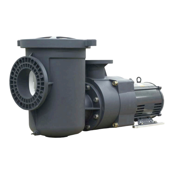
Section 1 Introduction Verus™ 850 Premium Efficient Aquaculture Duty Pump Overview • Efficient, quiet, lightweight and corrosion-resistant with • Optional bolt-on Strainer Pot (P/N 347013 innovative impeller design. • Self-priming pump • Available in single and three-phase, 50 and 60 Hz models • Some Models are ETL Listed, (see table on page 19) • 6” (15.24 cm) suction and 4” (10.16 cm) discharge with • CE Listed - Conforms with all health, safety and environmental strainer pot protection standards of the European Union. Applies to 50 Hz • Heat-resistant seal operates at up to 150° F (66 C°) models only, (see table on page 19). Pump Dimensions 14.0 MAX. 12.3 4" STD FLANGE + .01 16.35 –... -
Page 7: Installation
Section 2 Installation This pump is for use for aquaculture installations ONLY. Do not use with any type of swimming pool, hot tub, or spa. The following general information describes how to install the Verus™ 850 Premium Efficient Aquaculture Duty Pump. Note: Before installing this product, read and follow all warning notices and instructions starting on page ii. Installing the Pump Only a qualified service person should install the pump. Mechanical Installation and Pressure Testing Mechanical Installation 1. Carefully remove the pump unit and strainer pot assembly, if included, from its shipping package. - Page 8 OPTIONAL STRAINER POT ASSEMBLY CAUTION — Some off the shelf, non-Pentair, 6” flange adapters will not work with pump without the strainer pot. Note the tabs on the flange on the left, (Figure 3). These tabs will interfere with the strainer pot alignment lip on the housing.
-
Page 9: Pressure Testing
Pressure Testing Certain local codes require that the circulation system be pressure tested with a proof pressure before being commissioned into service or before allowing construction to progress to the next stage. WARNING — Improperly pressure testing a circulation system can involve significant risk of property damage or severe personal injury or death. Circulation systems store energy when pressure tested due to the elastic nature of the materials used in construction and due to the compressibility of air that may be contained in the system. -
Page 10: Pressure Relief Valve
Pressure Testing (Continued) Slowly apply the water pressure and allow the water to flow out all of the openings intended for air to escape. Close the openings beginning at the lowest level first and progressing to the highest level. Do not close any opening until you are sure that air is completely out of that part of the system. 8. Allow the pressure to slowly build once all of the air openings are closed. Close the valve between the water supply and circulation system to isolate the system from the supply pressure. 9. Monitor the system pressure for a few minutes to ensure that it is stabilized. WARNING — Due to the potential risk that can be involved it is recommended that the pressure test be kept to the minimum time required by the local code. Do not allow people to work around the system when the circulation system is under pressure test. -
Page 11: Electrical Requirements
Section 3 Electrical Requirements This section describes how to secure and wire the Verus™ 850 Aquaculture Duty Pump. Electrical Requirements and Field Wiring CAUTION — To prevent possible voltage reduction that cause flicker sensations in lighting equipment, this product should be powered by a dedicated power line capable of providing at least 32 A per phase. Other equipment connected to the same power line may experience operations problems caused by the inrush current during start-up of this product. - Page 12 Electrical Requirements and Field Wiring (Continued) 4. It is important that all portions of the electrical circuit including the conductors that connect the electrical panel to the pump motor are properly sized based on the nameplate information on the pump. 5. Following the National Electrical Code and any local electrical codes connect the grounding conductor and electrical supply conductors to the motor. Ensure that the pump is properly grounded per the above codes utilizing the grounding screw identified in the terminal box of the pump motor. 6. It will be necessary to confirm that the rotation of the motor is in the correct direction on all three-phase pump units and on certain single-phase pump units. Check wiring diagram to determine if motor can be field wired to rotate in both directions. Checking rotation by energizing the pump for one second and then watching the rotation through the back of the motor as it coasts to a stop. Ensure that the rotation matches the direction arrow on the pump. Operating a pump with the incorrect rotation can cause many problems including poor priming, diminished water flow, excessive noise, overloading of the motor and premature failure of the pump. NOTICE: Due to wide variation in electrical equipment, power equipment, power supply, and installation requirements, this manual does not make specific recommendations concerning auxiliary equipment or fusing/wiring.
-
Page 13: Initital Operation Of Pump
Section 4 Initial Operation of Pump WARNING — Do not operate the pump until you have read and understand clearly all the operating instructions and warning messages for all equipment that is a part of the circulating system. The following instructions are intended as a guide for initially operating the pump in a general pool installation, however each installation may have unique conditions where the starting procedure could be different. -
Page 14: Maintenance
Section 5 Maintenance Cleaning of the Strainer Basket 1. The pump is designed to be maintenance free with the exception of requiring a periodic cleaning of the strainer basket. 2. A routine inspection should be done by visually looking through strainer lid for debris while the pump is in operation. The strainer basket should be cleaned when approximately 25 % blocked. Allowing the strainer basket to become excessively blocked will diminish water flow, reduce pump efficiency, cause cavitation and may damage the basket or other pump components. 3. Disconnect power to the pump before cleaning the basket. 4. Close isolation valves on the suction and discharge lines if necessary to prevent flooding. WARNING — The strainer pot may be at a pressure that is higher or lower than the atmospheric pressure. Always open the drain plug on the strainer pot and allow for the pressure to equalize before removing the locking ring. -
Page 15: Preventative Maintenance
WARNING — It is recommended that only water and a soft cloth be used to clean the lid and other pump components. Cleaners may contain chemicals that could damage or weaken pump components causing them to fail and allowing an instantaneous release of energy. This instantaneous release of energy can cause components to be accelerated to high velocities and to travel distances of 100 feet (30.5 meters) or more. -
Page 16: Servicing
CAUTION — It is recommended that you replace the motor with the Pentair replacement motor as identified in Section 8. This motor has been thoroughly tested to ensure that it will function appropriately with the pump under a wide variety of operating conditions. If you choose to use another replacement motor it is important that the frame type, the HP, the service factor, the voltage, the phase and the motor speed match exactly to that listed on the original motor. -
Page 17: Assembling
2. Properly orient the motor adaptor (7) to the motor (1) and secure in place using the four screws (10) and Seal Plate Alignment Tool washers (8) (9). It is recommended to use the Pump (P/N 351137S) Seal Plate Alignment tool (Pentair P/N 351137S) when mounting the motor adaptor to ensure that the motor adaptor is perfectly aligned to the motor shaft, (see Figures 7 & 8). 3. Insert the two dowel pins (26) into the motor adaptor (7). 4. Install the stationary ring of the mechanical seal Figure 8. - Page 18 9. Apply a light film of silicone grease to the inside diameter of the brass bushing inside the diffuser (17). This film will assist in properly centering the diffuser bushing to the impeller (15) and will reduce the friction should the parts contact during motor start-up. DO NOT USE ANY OTHER TYPES OF LUBRICANTS. 10. Install the diffuser (17) over the impeller (15) and secure with the four screws (20), but only hand tight. The diffuser (17) has clearance around the four screws (20) that will allow adjustment of the fit of the diffuser (17) around the impeller (15) nose. Rotate the impeller (15) by hand to ensure that it is free to turn and slowly tighten each of the four screws (20). Verify that the impeller (15) is free to turn once the diffuser screws (20) are fully tightened. 11. Lubricate the diffuser O-Ring (21) and the larger seal plate O-Ring (28) with silicone lubricant or oil soap. This will allow the O-Rings to slip into place without getting pinched. Ensure that the big seal plate O-Ring (28) is properly seated on the large diameter of the seal plate (13). 12. Carefully slip the motor end assembly into the housing (22) pushing it forward as far as possible until the large seal plate O-Ring (28) comes into contact with the housing (22). Insert the four 6½ in. long screws (11) through the housing (22) and secure the assembly in place using the washers (12) and nuts (23). Gradually tighten each of the four screws a few turns in a crossing pattern to ensure that the motor assembly is properly centered to the housing. Do not over tighten these screws. CAUTION — Failure to follow the above assembly procedures could cause the impeller to bind once the pump is fully assembled. It is possible to remove the strainer basket, reach through the strainer pot and spin the impeller to verify that it will rotate freely.
-
Page 19: Troubleshooting
Section 7 Troubleshooting Use the following troubleshooting information to resolve possible problems with the pump. WARNING — RISK OF ELECTRICAL SHOCK OR ELECTROCUTION. Improper installation will create an electrical hazard which could result in death or serious injury to users, installers, or others due to electrical shock, and may also cause damage to property. 1. -
Page 20: Replacement Parts
Section 8 Replacement Parts Verus™ 850 Duty Pump Illustrated Parts Box A Purchase optional flange kit: 357262 - Flange 4” w/ Gasket & s/s Hardware 357263 - Flange 6” w/ Gasket & s/s Hardware 357212 - Flange 6” w/ Gasket & s/s Hardware (Optional) for use on EQ Series ®... -
Page 21: Verus 805 Pump Parts List
Verus™ 850 Duty Pump Parts List Item # Description Motor – See Table on prev. page. 356713 Support - Motor - {qty. 2} Support Adapter – See Table on prev. page. Washer, Flat 3/8" ID x 7/8" OD .05 Thk 18-8 s/s - 072184 {qty. -
Page 22: Strainer Pot Assembly Parts List
Strainer Pot Parts List Verus™ 850 Strainer Pot Assembly (P/N 347013) Item Part Description 356700 Clamp, Cam and Ramp Verus™ 850 Pump 356750 Lid, Verus™ 850 Pump Clear 350166 Gasket, Verus™ 850 Pump Lid 357184 Basket, Verus™ 850 Pump Strainer 356725 Pot, Verus™... -
Page 23: Pump Technical Data
Section 9 Pump Technical Data 50HZ PUMP PERFORMANCE CURVES 50HZ PUMP PERFORMANCE CURVES VERUS™ 850 SERIES PREMIUM EFFICIENT AQUACULTURE DUTY PUMP VERUS™ 850 SERIES PREMIUM EFFICIENT AQUACULTURE DUTY PUMP VREK5-40 VREK5-40 VREK5-30 VREK5-30 VREK5-20 VREK5-20 VREK5-12 VREK5-12 1000 1500 2000 2500 3000 FLOW RATE IN LPM... -
Page 24: Engineering Specifications
Engineering Specifications Part No. Part No. Full Load Service W/O Pot W/Pot Model Number Phase Voltage Amps* (FLA) Amps Factor 60 Hz Pump Models 347014 347026 VREW-12 - 1PH 6" x 4" 208/230 19.5-19.2 21.5 1.15 347016 347027 VREWK-12 - 3PH 6" x 4" 208-230/460 8.4-7.8/3.9 9.5-8.8/4.4... - Page 25 Notes VERUS 850 Premium Efficient Aquaculture Duty Pump Installation and User’s Guide ®...
- Page 26 Notes VERUS 850 Premium Efficient Aquaculture Duty Pump Installation and User’s Guide ®...
- Page 27 Notes VERUS 850 Premium Efficient Aquaculture Duty Pump Installation and User’s Guide ®...
- Page 28 All Pentair trademarks and logos are owned by Pentair Inc. Pentair Aquatic Eco-Systems, and Verus™ are trademarks and/or registered trademarks of Pentair Water Pool and Spa and/or its affiliated companies in the United States and/ or other countries. Unless expressly noted, names and brands of third parties that may be used in this document are not used to indicate an affiliation or endorsement between the owners of these names and brands and Pentair Aquatic Eco-Systems.
Need help?
Do you have a question about the Aquatic Eco-Systems Verus 850 and is the answer not in the manual?
Questions and answers