Advertisement
Quick Links
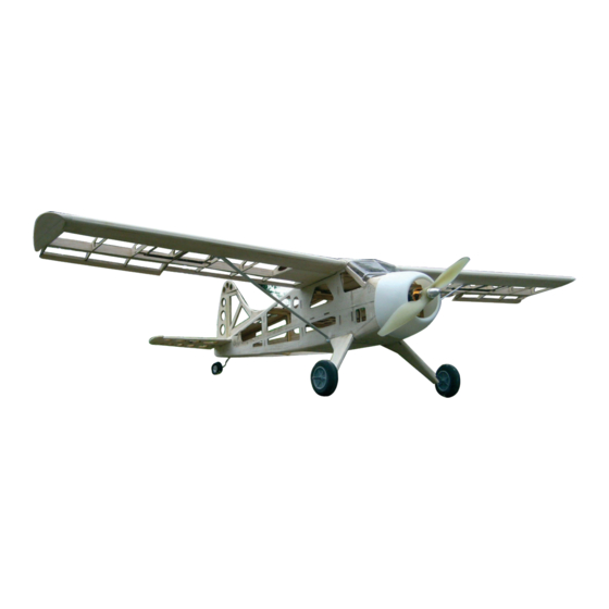
Beaver DHC 2 V2
Instruction
Read these instructions carefully before use.
Please keep these instruction after assembling.
Safety precautions
Safety precautions
!
This radio control model is not a toy!
This radio control model is not a toy!
Not suitable for persons under 14 years!
Not suitable for persons under 14 years!
* First-time builders should seek advice people having
* First-time builders should seek advice people having
building experience in order to assemble the model
building experience in order to assemble the model
correctly and to produce its performance to full extent.
correctly and to produce its performance to full extent.
* Assemble this kit only in places out of children's reach!
* Assemble this kit only in places out of children's reach!
* Take enough safety precautions prior to operating this
* Take enough safety precautions prior to operating this
model. You are responsible for this model's assembly and
model. You are responsible for this model's assembly and
safe operation!
safe operation!
* Always keep this instruction manual ready at hand for
* Always keep this instruction manual ready at hand for
quick reference, even after completing the assembly.
quick reference, even after completing the assembly.
GB
00 6135
Ord. No.
Advertisement

Related Manuals for Jamara Beaver DHC 2 V2


Summary of Contents for Jamara Beaver DHC 2 V2
- Page 1 Beaver DHC 2 V2 00 6135 Instruction Ord. No. Read these instructions carefully before use. Please keep these instruction after assembling. Safety precautions Safety precautions This radio control model is not a toy! This radio control model is not a toy!
-
Page 2: Safety Information
Attention! In some countries it is a legal requirement to carry third Party As the company JAMARA e.K. has no influence over the use, main- indemnity insurance when operating a radio controlled mo- tenance or conditions under which our products will operate, we accept no responsibility for any damage caused be it of a physical, del. - Page 3 Kit Contents: • CNC LASER cut formers and ribs, strip wood, selected light weight balsa sheet and aircraft grade plywood. • Fitting kit including wheels, undercarriage, horns and hinges. • Clear canopy. • Instructions. The motor mount is made of 2 x 1.5 mm plywood glued Have the 3 mm plywood rings with drive-in nuts ready.
- Page 4 The first fuselage frame is stuck to the motor mount. Before Stick the top cover in place. this, place the spout into place and and fold over side pieces. The next two pieces of the fuselage frame are now stuck to Now mount the rear fuselage frame.
- Page 5 11. Glue the wing support together and leave to dry. 12. Glue the undercarriage support and cockpit border at the top. 13. Glue the undercarriage wire support in place as shown. 14. The fuselage is prepared and glued. Tip: To avoid unnecessary edges, cover the edges and glue from the back with thin super glue to each other.
- Page 6 17. The next two fuselage frames are now placed between the 18. If swimmers are mounted later on, the bottom fuselage cover two side pieces and glued together. can be adjusted so that a second undercarriage wire can be Make sure they are straight! fitted later on.
- Page 7 23. 1.5 mm balsa strips are glued to the edges of the sides. 24. This pieces is sanded later on as well. Therefore lay out frame 1 and 2 with 4mm balsa. 25. Cover with 1.5 mm balsa. 26. It is recommended to apply a dummy empennage made of 4 mm balsa left overs before hand.
- Page 8 29. After removing the dummy, the gaps in the empennage can 30. The top cockpit section is glued with 1.5 mm balsa. be seen. 31. The sides of the window frame are glued with balsa. 32. Use 3 mm spring steel to shape the undercarriage 33.
- Page 9 35. … and adjust. 36. Finally, glue with 3 mm balsa to a “sandwich”. 37. If no rear wheel is added, we recommend to strengthen the 38. Steering shaft and rudder shaft are aligned collinear. The wire tail with 6 mm balsa. is guided through a piece bowden tube.
- Page 10 41. The two rudders are fitted together with a piece of spring 42. Sand the edges of the rudder. wire. 43. In this case the elevator is fitted with a foil hindge and this is 44. A groove is cut out in the back piece of the elevator. Insert the the reason why the edges are only sanded on one side.
- Page 11 47. Also the brackets are glued with two pcs. of plywood. 48. If the grooves of the ribs are aligned, two little noses will show. These fit later on in rib R1. 49. Wing halfs made from balsa ribs (sequence R2 - R9) and 50.
- Page 12 53. The landing flap bars are aligned. 54. The aileron panel at an oblique angle. Tip: To hang up the wing again to plan, the lower projection of the aileron panel remove the same. 55. Glue the edges of the rudder to the bar. 56.
- Page 13 59. Put a wet cloth on the outer wings so they can be formed 60. The edges of the planking is sanded until you reach the ribs. easier. Tip: Make sure all is aligned! The underside has to lay on the plan until the glue is dried. You may have to put weights on the opposite side.
- Page 14 65. Now the nose bar is glued. What is twisted now will stay like 66. Both wings are now sanded and are ready to be glued. this. With glueing the nose bar the wing will finally get its stability. Before you start glueing, the wing needs to be fxed to the building board.
- Page 15 71. Also sand the underside. 72. Polish. 73. Wings and fuselage can now be adjusted. 74. Two rings made of plywood support the material surounding The upper part of the fuselage above the wing is part of the the wing screws which are applied later. balsa established.
- Page 16 77. Then along the bar between bar and rudder with 78. A rudder is created which can be fitted with hindge tape or a utility knife to cut. foil. 79. Overlaying rib pieces can now be sanded. 80. To avoid creases in the foil around the rudder, a frame is created with 1.5 mm balsa.
- Page 17 83. Three layers from 1.5 mm 84. Ready for sanding 85. Servo mounting 86. The servo cover should be installed . Cut the hole for the servo cover the servo shafts in the wings. The second option shows the servo cover for the flap servos. 87.
- Page 18 Set-up: Aileron: 10 mm deflection Elevator: 10 mm deflection Rudder: 25 mm deflection 43 ~ 45 mm from the nose Down thrust ~ 2° down (already installed) Traction ~ 2 ~ 2,5 to the right (2˚ installed) Accessories Ord. No. 13 2217 Ord.
- Page 20 Plane - The original sized plan can be found on the DVD Top view...
- Page 21 Plane - The original sized plan can be found on the DVD Side...
- Page 22 Plane - The original sized plan can be found on the DVD Landing gear...
- Page 23 Notice...
- Page 24 Irrtum und technische Änderungen vorbehalten. Copyright JAMARA e.K. 2011 Kopie und Nachdruck, auch auszugsweise, nur mit Genehmigung von JAMARA e. K. Coupon Order the current catalogue with our complete assortment of modelling goods today. Name _______________________________ First name _______________________________ Street...
Need help?
Do you have a question about the Beaver DHC 2 V2 and is the answer not in the manual?
Questions and answers