Table of Contents
Advertisement
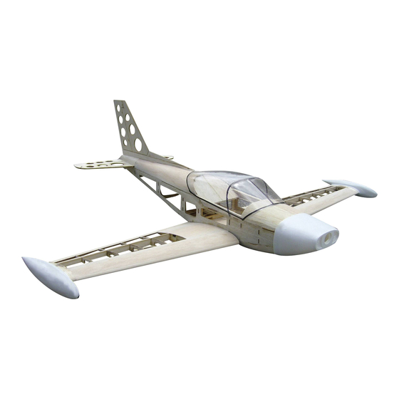
SIAI Marchetti SF-260
Instruction
Safety precautions
!
This radio control model is not a toy!
Suitable for persons over 14 years!
• First-time builders should seek advice people having
building experience in order to assemble the model
correctly and to produce its performance to full extent.
• Assemble this kit only in places out of children's reach!
• Take enough safety precautions prior to operating this
model. You are responsible for this model's assembly and
safe operation!
• Always keep this instruction manual ready at hand for quick
reference, even after completing the assembly.
GB
Ord. No.
It`s not a toy!
00 6138
Advertisement
Table of Contents

Related Manuals for Jamara SIAI Marchetti SF-260


Summary of Contents for Jamara SIAI Marchetti SF-260
-
Page 1: Safety Precautions
SIAI Marchetti SF-260 Instruction 00 6138 Ord. No. It`s not a toy! Safety precautions This radio control model is not a toy! Suitable for persons over 14 years! • First-time builders should seek advice people having building experience in order to assemble the model correctly and to produce its performance to full extent. • Assemble this kit only in places out of children’s reach! • Take enough safety precautions prior to operating this model. You are responsible for this model’s assembly and safe operation! • Always keep this instruction manual ready at hand for quick reference, even after completing the assembly. -
Page 2: Table Of Contents
DE - Inhalt Safety Information Building the Model 3 - 12 General Information Control Throws and Centre of Gravity Technical data Recommended Accessories Box contents Plans 14 - 17 Highlights Safety Information Important Information for use of batteries and battery packs This model is not a toy! Suitable for people over 14 year. • Adhere to the specification of how the batteries should be taken out or placed into the product. Note: Not suitable for children under 36 months. • Do not recharge disposable batteries! Risk of suffocation. • Rechargeable batteries should be taken out of the model before Contains small parts which can be swallowed. -
Page 3: General Information
GB - General Information As the company JAMARA e. K. has no influence over the use, main- Attention! tenance or conditions under which our products will operate, we In some countries it is a legal requirement to carry third par- accept no responsibility for any damage caused be it of a physical, ty indemnity insurance when operating a radio controlled model. Please ask your local dealer, governing body or your financial or theoretical nature. JAMARA e. K. will accept no claim insurance company for details. - Page 4 The joiner is glued together from 2 x 1.5 mm plywood. The ribs 2 - 9 are now stuck in the grooves and aligned perpendicular to the beam. Attention! Do not glue yet! The lower edge of the ribs is 1.5 mm above the rail. The The rear holm is inserted. front part of the ribs should now be backed with 1.5 mm Now align, fix the components together and use superglue. balsa to align the parts clean and to be able to align. Servo frame and undercarriage support are glued. Rib 1 and the trailing edge are glued. Depending on the undercarriage you may have to adjust. The dimensions are suitable for most small retracts.
- Page 5 The ailerons bar is inserted diagonally into the slot. 10. The auxiliary nose bar is glued to the bottom planking and ribs. Sand the edges a little so that it fits neatly over the upper cladding. The bottom planking can now be cut off. The wing must lie even and fixed to glue it. 11. Plank wing halfs in front are. 12. A 6 mm balsa-rest is cut and glued between rib 1 and 2 on the holm. 13. Sand neatly. 14. Now the leading edge is attached and glued.
- Page 6 15. The wing tip is composed of 3 x 6 mm balsa parts and glued to the end surface. 16. Planking the bottom-inner part. 17. The top of the wing can now be planked. 18. The leading edge is ground into shape and the joiner glued in one side of the spar. Due to tolerances in the thickness of wood this fit sometimes sits „too tight“. Sand the wing joiner until it is smooth to slide into the groove. Both halves can now be glued together without distortion.
- Page 7 19. First, the nuts with the spacer rings are glued on part F10. 20. The motor mount is mounted on the battery board. The wing is fixed to this part later on. 21. Please follow these instructions carefully! 22. Servo plate and side panels are stuck together. The motor carrier has camber and (right) train already installed. Part „ML“ should be assembled left, „MR“ right (in flight direction). 23. Wing surface and mounting are glued. 24. In the first module, the ribs are glued at right angles.
- Page 8 25. Also for the motor mount. 26. Glue all three components together as shown. 27. If an undercarriage is to be fitted two support brackets are 28. They are now glued between frame 1 and 2. made of 2 x 3 mm ply. 29. Side pieces are prepared. 30. And glued to the 3 x 4 mm edge strips...
- Page 9 31. As shown in the front section below. 32. Once the side pieces are glued to the ply cells, the bars will fit in the groove. 33. Same in the rear. 34. Now part 7 and 8 are glued between the sides. Glue the horizontal stabiliser and top bar. Now aligne the fuselage and correct the distortion. 35. Strips are then glued in front and below. 36. Mounted the rear of the cockpit.
- Page 10 37. Place 2 x 3 mm balsa strips (25mm wide) in front of you. 38. Sand the side panel edges with ribs. 39. And glue the balsa strips. 40. Same for the front part 41. However, cover with 6 mm. The grain vertical. 42. Now, the front region is planked at top and bottom. TIP: Wet the wood on the outside, then it can be bent just fine.
- Page 11 43. The overlap is sanded to fit. 44. The rear fuselage is planked at the top. 45. The rear end is constructed from 6 mm balsa. 46. A dummy of the tail (residues from 4 mm) frees up the space for the tail later. 47. Now 6 mm balsa is glued above the 6 mm balsa 48. Once everything is sanded to the contour of the fuselage, the dummy can be pulled out by the back. IMPORTANT: Only glue to rib 8! And let dry thoroughly.
-
Page 12: Control Throws And Centre Of Gravity
Optional retract mounting (Retracts not included) Mounting the front mechanism. If necessary, frames must be sawed. Mechanics mounted in wing. Cut-out for wheel Set-up: Aileron: +/- 8 - 12 mm deflection Elevator: +/- 6 mm deflection Rudder: +/- 15 mm deflection CG: 42 - 44mm from the nose... -
Page 13: Recommended Accessories
Recommended Accessories Accessories Set No.: 4368 Contents: No. 13 2210 No. 08 1925 No. 34 0120 No. 14 1368 Motor A2212/10-BI Controller Xetronic 25A Propeller Battery AEJ electro 9 x 6 LiPoStar Turbo 11,1 V 1800 mAh No. 03 3212 4 x Servos High End Micro 9 g... -
Page 14: Plans
Plane - The original sized plan can be found on the DVD... - Page 15 Plane - The original sized plan can be found on the DVD...
- Page 16 Plane - The original sized plan can be found on the DVD...
- Page 17 Plane - The original sized plan can be found on the DVD...
- Page 20 Der Katalog wird mit der nächsten Bestellung des Händ- lers auf Ihren Namen mitgeliefert. We will include a catalogue for your attention with the next order placed by your dealer. Newsletter Aktuelle Neuheiten erfahren Sie in unserem Newsletter. Soll- ten Sie daran Interesse haben, abbonieren Sie den Jamara Newsletter. Ihre E-mail-Adresse ______________________________________________________ You can receive up-to-date news through our newsletter. If you are interested, plese apply for the Jamara Newsletter.
Need help?
Do you have a question about the SIAI Marchetti SF-260 and is the answer not in the manual?
Questions and answers