Advertisement
Quick Links
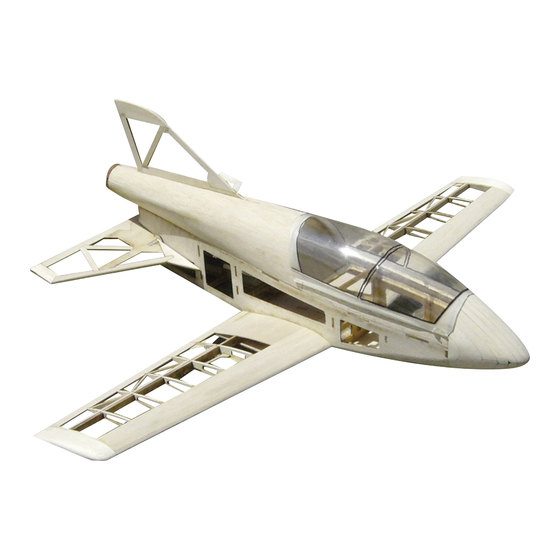
BD-5
Instruction
Read these instructions carefully before use.
Please keep these instruction after assembling.
Safety precautions
!
This radio control model is not a toy!
Not suitable for persons under 14 years!
* First-time builders should seek advice people having
building experience in order to assemble the model
correctly and to produce its performance to full extent.
* Assemble this kit only in places out of children's reach!
* Take enough safety precautions prior to operating this
model. You are responsible for this model's assembly and
safe operation!
* Always keep this instruction manual ready at hand for
quick reference, even after completing the assembly.
GB
00 6136
Ord. No.
Advertisement

Related Manuals for Jamara BD-5


Summary of Contents for Jamara BD-5
-
Page 1: Safety Precautions
BD-5 00 6136 Instruction Ord. No. Read these instructions carefully before use. Please keep these instruction after assembling. Safety precautions This radio control model is not a toy! Not suitable for persons under 14 years! * First-time builders should seek advice people having building experience in order to assemble the model correctly and to produce its performance to full extent. -
Page 2: Safety Information
General Information Attention! As the company JAMARA e.K. has no influence over the use, main- In some countries it is a legal requirement to carry third Party indemnity insurance when operating a radio controlled mo- tenance or conditions under which our products will operate, we accept no responsibility for any damage caused be it of a physical, del. - Page 3 Kit Contents: • CNC LASER cut formers and ribs, strip wood, selected light weight balsa sheet and aircraft grade plywood. • Fitting kit including wheels, undercarriage, horns and hinges. • Clear canopy. • Instructions. Glue the rings on the holes Now insert the drive-in nut.
- Page 4 Apply the side piece and glue. The front piece is later taken Glue the wing screws support off to make room for the battery Both wing supports are glued and leave to dry. Rear and front fuselage pieces are put together as shown. First of all, only glue the side pieces to the front and leave to 10.
- Page 5 11. Fuselage, upper part: 12. Straighten the fuselage borders and glue to the grooves. Use 3 mm ply on the left and right side and it is lapping over. The front lower fuselage is covered with 2 mm balsa and The fin is later fitted in the gap.
- Page 6 17. Start assembly from the middle and move to the right/ left 18. The layers should overlap each other. from there. 19. The fuselage nose sanded. 20. Now the rear fuselage piece is covered. Use a sheet of balsa and glue to the bottom edge. 21.
- Page 7 23. Fuselage cover on the underside of the cockpit. 24. Rudder 25. Elevator 26. As a pivot, a 4 mm aluminum rod is fitted with a plywood control horn (2 x 1.5 mm) with 5min. Epoxy. The rudder horn is vertical to the fin. Fill the groove, completely with rod and resin.
- Page 8 29. Ready assembled pivot-system 30. You can use a pole as shown for the controls. For example: made of 2x3mm balsa (hard) with spring wire in-between. The linkage to the elevator has to be stable once tension is applied and should not deform. 31.
- Page 9 35. Further ribs are applied to the wing spar in order R9. The last 36. The servo bay is glued to the underside rib is glued and the others aligned. 37. The first rib is now glued after a 1,5 mm is put under it. This 38.
- Page 10 41. The aileron border is slided in the grooves and glued. 42. The aileron is later taken from the two ribs 43. The tip is now glued together made from 2 x 6 mm balsa. 44. The wing parts are now covered in the inner/ lower part. 45.
- Page 11 47. Sanded 48. The edges are sanded 49. The connection rod is made of 2x 1,5 mm ply which is also 50. Glue both parts of the wings together. used on the plane. Slot it in once ready. 51. Example for assembly of the servo hatch cover. 52.
- Page 12 53. Overlying rib material can now be sanded. 54. So the covering foil does not crease in the region of the aileron, a “frame” is build for the rudder horn made of 1,5 mm balsa. Once the covering is done, the pocket can be cut out and the rudder horn glued into place.
- Page 13 Set-up: Aileron 10 - 15 mm deflection Elevator 10 - 15 mm deflection Manual start: with ~ 70% elevator pulled (for example, program as flight phase) 37 - 39 mm from the nose Downthrust ~ 5-7 ° up (installed 5°, according to engine and propeller with washer to alter) Engine course ~ 0°...
- Page 14 Plane - The original sized plan can be found on the DVD...
- Page 16 All rights reserved. Copyright JAMARA e.K. 2011 Copying or reproduction in whole or part, only with the expressed permission of JAMARA e.K. Coupon Order the current catalogue with our complete assortment of modelling goods today. Name _______________________________ First name _______________________________...
Need help?
Do you have a question about the BD-5 and is the answer not in the manual?
Questions and answers