Table of Contents
Advertisement
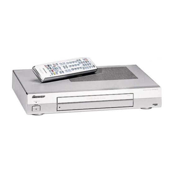
PDP-R03E
THIS MANUAL IS APPLICABLE TO THE FOLLOWING MODEL(S) AND TYPE(S).
Model
Type
PDP-R03E
WYVI6
¶ Please connect it to the PLASMA DISPLAY PDP-503PE or PDP-433PE, for adjustment
and operation inspection.
Component
PLASMA DISPLAY SYSTEM
PLASMA DISPLAY
MEDIA RECEIVER
CONTENTS
1. SAFETY INFORMATION ...................................... 3
2. EXPLODED VIEWS AND PARTS LIST ................ 4
4. PCB CONNECTION DIAGRAM .......................... 64
5. PCB PARTS LIST ............................................... 71
6. ADJUSTMENT .................................................... 96
For details, refer to "Important symbols for good services" on the next page.
PIONEER CORPORATION
PIONEER ELECTRONICS (USA) INC. P.O. Box 1760, Long Beach, CA 90801-1760, U.S.A.
PIONEER EUROPE NV Haven 1087, Keetberglaan 1, 9120 Melsele, Belgium
PIONEER ELECTRONICS ASIACENTRE PTE. LTD. 253 Alexandra Road, #04-01, Singapore 159936
PIONEER CORPORATION 2001
STANDBY/ON
POWER
Power Requirement
AC220-240V
System
PDP-503HDE
PDP-503PE
–––
PDP-R03E
4-1, Meguro 1-chome, Meguro-ku, Tokyo 153-8654, Japan
Service Manual
PDP-433HDE
–––
–––
ARP3107, ARP3108
PDP-433PE
ARP3111, ARP3112
ARP3110
7. GENERAL INFORMATION .............................. 102
7.1 DIAGNOSIS ............................................... 102
7.1.1 TROUBLE SHOOTING ...................... 102
7.1.2 DISASSEMBLY .................................. 107
7.2 EXPLANATION .......................................... 108
7.2.1 IC DESCRIPTIONS ............................ 108
PDP-R03E
MEDIA RECEIVER
ORDER NO.
ARP3110
Remarks
Remarks
This manual.
T – ZZK NOV. 2001 Printed in Japan
Advertisement
Table of Contents

Subscribe to Our Youtube Channel
Related Manuals for Pioneer PDP-R03E


Summary of Contents for Pioneer PDP-R03E
- Page 1 PIONEER CORPORATION 4-1, Meguro 1-chome, Meguro-ku, Tokyo 153-8654, Japan PIONEER ELECTRONICS (USA) INC. P.O. Box 1760, Long Beach, CA 90801-1760, U.S.A. PIONEER EUROPE NV Haven 1087, Keetberglaan 1, 9120 Melsele, Belgium PIONEER ELECTRONICS ASIACENTRE PTE. LTD. 253 Alexandra Road, #04-01, Singapore 159936 PIONEER CORPORATION 2001 T –...
- Page 2 PDP-R03E [ Important symbols for good services ] In this manual, the symbols shown-below indicate that adjustments, settings or cleaning should be made securely. When you find the procedures bearing any of the symbols, be sure to fulfill them: 1. Product safety You should conform to the regulations governing the product (safety, radio and noise, and other regulations), and should keep the safety during servicing by following the safety instructions described in this manual.
-
Page 3: Safety Information
, a l w a y s c o n s u l t t h e c u r r e n t P I O N E E R Service Manual. A subscription to, or additional copies Also test with plug reversed of, PIONEER Service Manual may be obtained at a (Using AC adapter Earth nominal charge from PIONEER. -
Page 4: Exploded Views And Parts List
PDP-R03E 2. EXPLODED VIEWS AND PARTS LIST NOTES: Parts marked by "NSP" are generally unavailable because they are not in our Master Spare Parts List. mark found on some component parts indicates the importance of the safety factor of the part. - Page 5 PDP-R03E • PACKING PARTS LIST Mark No. Description Part No. Power Cord (For Europe) QACCBA005WJZZ Power Cord (For U.K.) QACCVA002WJZZ System Cable QCNW-6117CEZZ Remote Control Unit RRMCG1677CESA Battery (AA) • • • • • • Operation Instructions TINS-7495CEZZ Operation Instructions...
-
Page 6: Exterior Section
PDP-R03E 2.2 EXTERIOR SECTION 2-17 2-10 2-13 2-14 2-11 2-12 2-17 2-15 2-16... - Page 7 • • • • • • No. Label TLABN0382CEZZ 2-2 LED Cover GCOVA2015CEKA Screw LX-BZ3434CEFN 2-3 Door GDORF3026CEKA Screw LX-LZ1005AEZZ 2-4 Pioneer Badge • • • • • • LX-NZ3182CEFN 2-5 Decoration Plate HDECP0171CESA Screw XBBSN30P06000 2-6 Control Indicator HINDP5840CESA Screw XBPSD30P06JS0...
-
Page 8: Blockdiagram And Schematic Diagram
PDP-R03E 3. BLOCK DIAGRAM AND SCHEMATIC DIAGRAM 3.1 BLOCK DIAGRAM 3.1.1 SYSTEM BLOCK DIAGRAM... - Page 9 PDP-R03E...
- Page 10 PDP-R03E 3.1.2 SIGNAL FLOW BLOCK DIAGRAM...
- Page 11 PDP-R03E...
- Page 12 PDP-R03E 3.1.3 DC/DC CONVERTER BLOCK DIAGRAM...
- Page 13 PDP-R03E...
- Page 14 PDP-R03E 3.1.4 POWER BLOCK DIAGRAM...
- Page 15 PDP-R03E...
- Page 16 PDP-R03E 3.1.5 PC I/F BLOCK DIAGRAM CPCI-00 56CE 25MHz CLR_ SW MCK_REF DCLK PC _H V0_HSYNC DO_RA[9.. 2 ] OV0 _H P C_V OV0_V V0_VSYNC DO_GA[9.. 2 ] P C_C PC_ C3 V0_CSYNC DO_BA[9..2] Sync LCLK IC411 MAIN _H 74LCX157...
- Page 17 PDP-R03E VGA_OE 25.175MHz WXGA_OE 5V->3.3V R eg 79.794MHz IC412 PQ1 R33 EEPROM D[23..16] 1:VD+5 IC414 D[15..8] 3:VA+5 PanelLink M24C32 D[7..0] HDCP 5,6:VD+2.5 Transmitter 8:VD+3.3 LCLK(79.79 4MHz) IDCK+ TMDS(4ch) IC413 DO_HS YNC HSYNC SiI168 C=CH1 10:V-5 DO_VS YNC VSYNC (TO MONITOR)
- Page 18 PDP-R03E 3.1.6 PRINTED WIRING BOARD BLOCK DIAGRAM PC I/F UNIT VIDEO PROCESSOR CIRCUIT POWER REG. CPCI-0 0 5 6 CE CPCI-0 0 5 6 CE CPCI-0 0 5 6 CE CPCI-0 0 5 6 CE CIRCUIT IC320 IC319 PANEL LINK...
-
Page 19: Main Unit
PDP-R03E MAIN UNIT SC1503 IC802 CONNECTOR SUB VIDEO CHROMA IC402 IC405 SUB COMB FIL. MAIN COMB FIL. IC901 IC403 IC406 CONTROL CONTROL IC604 SYNC SEP. P1702 CONNECTOR IC803 IC1502 RGB DECODER P901 IC801 ADJUSTING MAIN VIDEO CONNECTOR P1703 CHROMA CONNECTOR... - Page 20 PDP-R03E DESCRIPTION OF SCHEMATIC DIAGRAM VOLTAGE MEASUREMENT CONDITION: 1. When the exclusive-use AC adapter is used, the colour bar signal of colour bar generator for service is input to get the normal screen. When the audio is minimized, the voltage value is measured with the 20 kΩ/V tester.
- Page 21 PDP-R03E WAVEFORMS IC1301 63-pin IC1301 56-pin IC405 1, 2-pin IC801 1-pin V: 200mV/div H: 10µsec/div V: 500mV/div H: 10µsec/div V: 500mV/div H: 10µsec/div V: 200mV/div H: 10µsec/div IC803 TP801 IC803 TP802 IC803 TP803 IC803 31-pin V: 200mV/div H: 20µsec/div V: 200mV/div H: 20µsec/div V: 200mV/div H: 20µsec/div...
- Page 22 PDP-R03E 3.2 OVERALL WIRING DIAGRAM (1/2) PDP-R03E SR CONNECT UNIT P6000 P6001 UNIT PC I/F UNIT QCNW-6084CEZZ QCNW-6083CEZZ QCNW-6077CEZZ CN702 POWER UNIT P3001 LED UNIT...
- Page 23 PDP-R03E Note : When ordering service parts, be sure to refer to "EXPLODED VIEWS and PARTS LIST" or "PCB PARTS LIST". QCNW-6078CEZZ QCNW-6075CEZZ AV UNIT SC1401 QCNW-6082CEZZ P2502 SC1503 QCNW-6081CEZZ QCNW-6073CEZZ QCNW-6080CEZZ P1702 MAIN UNIT P1703 QCNW-6074CEZZ QCNW-6079CEZZ P2401 P2402...
- Page 24 PDP-R03E 3.3 OVERALL WIRING DIAGRAM (2/2) 1/7-7/7 PC I/F UNIT (CPCI-0056CE11) SR CONNECT UNIT (DUNTKA 594DE01) FRONT UNIT UNIT (DUNTKA (DUNTKA536DE01) 649DE01) 1/3-3/3 AV UNIT (DUNTKA537DE01)
- Page 25 PDP-R03E 1/6-6/6 MAIN UNIT (DUNTKA535DE01) UNIT (RDENCA POWER UNIT 006WJZZ) (RDENC0331CEZZ)
- Page 26 PDP-R03E 3.4 MAIN UNIT (1/6) MAIN UNIT (DUNTKA535DE01)
-
Page 27: Table Of Contents
PDP-R03E... - Page 28 PDP-R03E 3.5 MAIN UNIT (2/6) MAIN UNIT (DUNTKA535DE01)
-
Page 29: Table Of Contents
PDP-R03E... - Page 30 PDP-R03E 3.6 MAIN UNIT (3/6) MAIN UNIT (DUNTKA535DE01)
- Page 31 PDP-R03E...
-
Page 32: Table Of Contents
PDP-R03E 3.7 MAIN UNIT (4/6) MAIN UNIT (DUNTKA535DE01) -
Page 33: Table Of Contents
PDP-R03E... - Page 34 PDP-R03E 3.8 MAIN UNIT (5/6) MAIN UNIT (DUNTKA535DE01)
- Page 35 PDP-R03E...
- Page 36 PDP-R03E 3.9 MAIN UNIT (6/6) MAIN UNIT (DUNTKA535DE01)
- Page 37 PDP-R03E...
-
Page 38: Front Unit
PDP-R03E 3.10 FRONT UNIT FRONT UNIT (DUNTKA536DE01) SW3401 : CLEAR... - Page 39 PDP-R03E...
- Page 40 PDP-R03E 3.11 AV UNIT (1/3) AV UNIT (DUNTKA537DE01)
- Page 41 PDP-R03E...
- Page 42 PDP-R03E 3.12 AV UNIT (2/3) AV UNIT (DUNTKA537DE01)
- Page 43 PDP-R03E P1703...
- Page 44 PDP-R03E 3.13 AV UNIT (3/3) AV UNIT (DUNTKA537DE01)
- Page 45 PDP-R03E...
- Page 46 PDP-R03E 3.14 SR CONNECT UNIT SR CONNECT UNIT (DUNTKA594DE01) P2502...
- Page 47 PDP-R03E 3.15 LED UNIT LED UNIT (DUNTKA649DE01) P2503...
- Page 48 PDP-R03E 3.16 PC I/F UNIT (1/7) PC I/F UNIT (CPCI-0056CE11)
- Page 49 PDP-R03E...
- Page 50 PDP-R03E 3.17 PC I/F UNIT (2/7) SC1502...
- Page 51 PDP-R03E PC I/F UNIT (CPCI-0056CE11)
- Page 52 PDP-R03E 3.18 PC I/F UNIT (3/7)
- Page 53 PDP-R03E PC I/F UNIT (CPCI-0056CE11)
- Page 54 PDP-R03E 3.19 PC I/F UNIT (4/7) PC I/F UNIT (CPCI-0056CE11)
- Page 55 PDP-R03E...
- Page 56 PDP-R03E 3.20 PC I/F UNIT (5/7)
- Page 57 PDP-R03E PC I/F UNIT (CPCI-0056CE11)
- Page 58 PDP-R03E 3.21 PC I/F UNIT (6/7) PC I/F UNIT (CPCI-0056CE11)
- Page 59 PDP-R03E...
- Page 60 PDP-R03E 3.22 PC I/F UNIT (7/7) PC I/F UNIT (CPCI-0056CE11)
- Page 61 PDP-R03E...
- Page 62 PDP-R03E 3.23 POWER and EMC UNITS (LIVE) (NEUTRAL) EMC UNIT (RDENCA006WJZZ) (LIVE) (LIVE) (NEUTRAL) (NEUTRAL) • NOTE FOR FUSE REPLACEMENT FOR CONTINUED PROTECTION AGAINST RISK OF FIRE. CAUTION - REPLACE WITH SAME TYPE AND RATINGS ONLY.
- Page 63 PDP-R03E POWER UNIT (RDENC0331CEZZ)
-
Page 64: Pcb Connection Diagram
PDP-R03E 4. PCB CONNECTION DIAGRAM 4.1 MAIN UNIT NOTE FOR PCB DIAGRAMS : MAIN UNIT • Part numbers in PCB diagrams match those in the schematic diagrams. • The parts mounted on this PCB include all necessary parts for several destinations. - Page 65 PDP-R03E MAIN UNIT Q1710 Q1718 Q1708 Q1701 Q1719 Q1713 IC1701 IC1713 IC1504 IC1710 Q1716 Q1726 Q1712 IC1711 IC1712 IC7003 Q7002 Q7010 IC7002 IC407 Q407 Q408 Q414 Q415 Q416 Q420 Q421 Q428 IC602 Q601 Q615 IC1708 IC404 IC605 Q621 IC814 Q7202...
- Page 66 PDP-R03E 4.2 FRONT, LED and SR CONNECT UNITS FRONT UNIT P1301 IC3401 Q3403 Q3402 Q3401 LED UNIT P2503 SR CONNECT UNIT Q6004 Q6003 Q6001 Q6002 Q6006 Q6005 P2502 SIDE A...
- Page 67 PDP-R03E 4.3 AV UNIT AV UNIT Q1133 Q1124 Q1120 IC1103 IC1105 IC1104 Q1131 Q1135 IC2501 IC2504 IC1606 IC1604 IC1601 IC1603 IC1602 IC1611 IC1012 IC1605 IC1606 IC1615 IC1614 IC1609 IC1613 Q1113 Q1117 IC1102 Q1105 Q1106 Q1107 IC2503 SC1504 P1703 Q1609 Q1610...
- Page 68 PDP-R03E 4.4 PC I/F UNIT PC I/F UNIT P6000 Q102 IC413 IC400 IC405 IC418 IC53 IC319 IC25 IC320 IC411 IC324 IC310 IC423 IC326 IC323 IC316 IC327 P1702 P3401 SC1501 SC1502 SIDE A...
- Page 69 PDP-R03E PC I/F UNIT Q103 IC414 IC19 IC27 IC28 IC321 Q120 IC404 IC402 IC422 IC322 IC408 IC421 IC410 IC328 Q104 Q119 IC420 IC419 IC407 Q101 IC415 SIDE B...
- Page 70 PDP-R03E 4.5 POWER and EMC UNITS POWER UNIT Q708 Q709 Q701 Q703 Q704 Q702 IC701 IC702 Q707 IC703 Q706 Q705 P1502 EMC UNIT LIVE AC IN NEUTRAL SIDE A...
-
Page 71: Pcb Parts List
PDP-R03E Mark No. Description Part No. Mark No. Description Part No. 5. PCB PARTS LIST • NOTES: Parts marked by "NSP" are generally unavailable because they are not in our Master Spare Parts List. • mark found on some component parts indicates the importance of the safety factor of the part. - Page 72 PDP-R03E Mark No. Description Part No. Mark No. Description Part No. Q805 DTC144EE VSDTC144EE/-1 D1706 Diode VHDSFPB74//2E Q807 2SC3928AR VS2SC3928AR-1 D1708 Zener Diode RH-EX0501CEZZ Q808 2SA1530AR VS2SA1530AR-1 D1709 Zener Diode RH-EX0501CEZZ Q809 2SC3928AR VS2SC3928AR-1 D1710 Zener Diode RH-EX0523CEZZ Q810 2SA1530AR...
- Page 73 PDP-R03E Mark No. Description Part No. Mark No. Description Part No. C606 0.01 50V Ceramic VCKYCY1HB103K CAPACITORS C609 33 10V Electrolytic VCEAPF1AW336M C403 22 6.3V Electrolytic VCEAPF0JW226M C611 33 10V Electrolytic VCEAPF1AW336M C404 0.1 25V Ceramic VCKYCY1EF104Z C612 33 10V Electrolytic...
- Page 74 PDP-R03E Mark No. Description Part No. Mark No. Description Part No. C808 0.1 25V Ceramic VCKYTV1EB104K C876 2200p 50V Ceramic VCKYCY1HB222K C809 0.1 25V Ceramic VCKYTV1EB104K C877 0.47 16V Ceramic VCKYTV1CB474K C810 4.7 25V Electrolytic VCEAPF1EW475M C878 0.47 16V Ceramic...
- Page 75 PDP-R03E Mark No. Description Part No. Mark No. Description Part No. C954 0.1 25V Ceramic VCKYCY1EF104Z C1766 220 16V Electrolytic RC-EZ1339CEZZ C1502 0.1 25V Ceramic VCKYCY1EF104Z C1767 1.0 16V Ceramic VCKYTV1CF105Z C1503 0.1 25V Ceramic VCKYCY1EF104Z C1768 330 16V Electrolytic...
- Page 76 PDP-R03E Mark No. Description Part No. Mark No. Description Part No. R410 2.7k 1/16W Metal Oxide VRS-CY1JF272F R485 0 1/16W Metal Oxide VRS-CY1JF000J R411 3.3k 1/16W Metal Oxide VRS-CY1JF332F R499 330 1/16W Metal Oxide VRS-CY1JF331J R412 560 1/16W Metal Oxide VRS-CY1JF561J R500 1.0k 1/16W Metal Oxide VRS-CY1JF102J...
- Page 77 PDP-R03E Mark No. Description Part No. Mark No. Description Part No. R641 6.8k 1/16W Metal Oxide VRS-CY1JF682J R803 100 1/16W Metal Oxide VRS-CY1JF101J R642 47 1/16W Metal Oxide VRS-CY1JF470J R805 27k 1/16W Metal Oxide VRS-CY1JF273J R643 680 1/16W Metal Oxide VRS-CY1JF681J...
- Page 78 PDP-R03E Mark No. Description Part No. Mark No. Description Part No. R896 2.2k 1/16W Metal Oxide VRS-CY1JF222J R962 1.0k 1/16W Metal Oxide VRS-CY1JF102J R898 10k 1/16W Metal Oxide VRS-CY1JF103J R963 47 1/16W Metal Oxide VRS-CY1JF470J R899 10k 1/16W Metal Oxide VRS-CY1JF103J R964 4.7k 1/16W Metal Oxide VRS-CY1JF472J...
- Page 79 PDP-R03E Mark No. Description Part No. Mark No. Description Part No. R1534 100 1/16W Metal Oxide VRS-CY1JF101J R1783 1.0k 1/16W Metal Oxide VRS-CY1JF102F R1535 47k 1/16W Metal Oxide VRS-CY1JF473J R1784 12k 1/16W Metal Oxide VRS-CY1JF123J R1538 22k 1/16W Metal Oxide VRS-CY1JF223J R1785 4.7k 1/16W Metal Oxide VRS-CY1JF472J...
- Page 80 PDP-R03E Mark No. Description Part No. Mark No. Description Part No. P1502 Plug 12-pin QPLGN0549FJZZ MISCELLANEOUS PARTS P1504 Plug 10-pin QPLGN0060CEZZ F1702 Fuse 4A QFS-D0011CEZZ P1702 Plug 13-pin QPLGN0550FJZZ FB401 Ferrite Bead RBLN-0061TAZZ P1703 Plug 12-pin QPLGN0062CEZZ FB601 Ferrite Bead...
- Page 81 PDP-R03E Mark No. Description Part No. Mark No. Description Part No. C3423 0.1 25V Ceramic VCKYCY1EF104Z SWITCHE C3426 10 25V Electrolytic VCEAPW1EN106M SW3401 CLEAR Button QSW-K0069CEZZ C3427 10 25V Electrolytic VCEAPW1EN106M C3428 100p 50V Ceramic VCCCCY1HH101J C3429 100p 50V Ceramic...
- Page 82 PDP-R03E Mark No. Description Part No. Mark No. Description Part No. Q1106 2SC3928AR VS2SC3928AR-1 D1128 Zener Diode RH-EX0674GEZZ Q1107 DTC314TK VSDTC314TK/-1 D1130 Zener Diode RH-EX0882CEZZ Q1108 2SC3928AR VS2SC3928AR-1 D1131 Zener Diode RH-EX0882CEZZ Q1109 DTC314TK VSDTC314TK/-1 D1132 Zener Diode RH-EX0882CEZZ Q1110...
- Page 83 PDP-R03E Mark No. Description Part No. Mark No. Description Part No. L1107 Peaking 4.7µH VP-1M4R7J1R2N C1146 1.0 16V Ceramic VCKYTV1CB105K L1108 Peaking 2.7µH VP-1M2R7JR85N C1147 10p 50V Ceramic VCCCCY1HH100D L1109 Peaking 4.7µH VP-1M4R7J1R2N C1148 220p 50V Ceramic VCKYCY1HB221K L1110 Peaking 4.7µH...
- Page 84 PDP-R03E Mark No. Description Part No. Mark No. Description Part No. C1207 470 16V Electrolytic VCEAPW1CN477M C1418 1.0 16V Ceramic VCKYTV1CB105K C1208 470 16V Electrolytic VCEAPW1CN477M C1419 0.1 25V Ceramic VCKYCY1EF104Z C1209 1.0 50V Electrolytic VCEAPF1HW105M C1422 100 16V Electrolytic...
- Page 85 PDP-R03E Mark No. Description Part No. Mark No. Description Part No. C2512 3300p 50V Ceramic VCKYCY1HB332K R1140 100k 1/16W Metal Oxide VRS-CY1JF104J C2513 3300p 50V Ceramic VCKYCY1HB332K R1141 1.0k 1/16W Metal Oxide VRS-CA1JF102J C2514 3300p 50V Ceramic VCKYCY1HB332K R1143 560 1/16W Metal Oxide VRS-CY1JF561J...
- Page 86 PDP-R03E Mark No. Description Part No. Mark No. Description Part No. R1208 560k 1/16W Metal Oxide VRS-CY1JF564J R1270 22k 1/16W Metal Oxide VRS-CY1JF223J R1209 75 1/8W Metal Oxide VRS-TQ2BD750J R1272 100 1/16W Metal Oxide VRS-CY1JF101J R1210 100 1/16W Metal Oxide VRS-CY1JF101J...
- Page 87 PDP-R03E Mark No. Description Part No. Mark No. Description Part No. R1345 0 1/16W Metal Oxide VRS-CY1JF000J R1626 1.0k 1/16W Metal Oxide VRS-CY1JF102J R1346 1.0k 1/16W Metal Oxide VRS-CY1JF102J R1627 1.0k 1/16W Metal Oxide VRS-CY1JF102F R1347 47k 1/16W Metal Oxide VRS-CY1JF473J...
- Page 88 PDP-R03E Mark No. Description Part No. Mark No. Description Part No. R2524 2.2k 1/16W Metal Oxide VRS-CY1JF222J FB2506 Ferrite Bead RBLN-0051TAZZ R2525 22k 1/16W Metal Oxide VRS-CY1JF223J FB2507 Ferrite Bead RBLN-0051TAZZ R2526 5.6k 1/16W Metal Oxide VRS-CY1JF562J J1101 Terminal, INPUT3...
- Page 89 PDP-R03E Mark No. Description Part No. Mark No. Description Part No. R6013 0 1/8W Metal Oxide VRS-TQ2BD000J PC I/F UNIT R6014 0 1/8W Metal Oxide VRS-TQ2BD000J R6015 220 1/16W Metal Oxide VRS-CY1JF221J INTEGRATED CIRCUITS R6016 4.7k 1/16W Metal Oxide VRS-CY1JF472J...
- Page 90 PDP-R03E Mark No. Description Part No. Mark No. Description Part No. 0.01 50V Ceramic 9DK001-42096 DIODES 10 10V Ceramic 9DK001-42131 Diode 1SS187 9DK001-30018 or 10 25V Ceramic 9DK001-42118 Diode 1SS187 9DK001-30018 15p 50V Ceramic 9DK001-42103 Diode 1SS193 9DK001-30001 15p 50V Ceramic...
- Page 91 PDP-R03E Mark No. Description Part No. Mark No. Description Part No. C125 0.1 25V Ceramic 9DK001-42094 C584 0.01 50V Ceramic 9DK001-42096 C126 0.1 25V Ceramic 9DK001-42094 C585 0.01 50V Ceramic 9DK001-42096 C127 100p 50V Ceramic 9DK001-42099 C586 0.01 50V Ceramic...
- Page 92 PDP-R03E Mark No. Description Part No. Mark No. Description Part No. C826 0.1 25V Ceramic 9DK001-42094 C894 0.1 25V Ceramic 9DK001-42094 C827 0.1 25V Ceramic 9DK001-42094 C895 0.1 25V Ceramic 9DK001-42094 C828 0.1 25V Ceramic 9DK001-42094 C896 0.1 25V Ceramic...
- Page 93 PDP-R03E Mark No. Description Part No. Mark No. Description Part No. R664 15k 1/16W Chip1608 9DK001-50259 R921 100 1/16W Chip1608 9DK001-50165 R665 15k 1/16W Chip1608 9DK001-50259 R922 10k 1/16W Chip1608 9DK001-50185 R671 15k 1/16W Chip1608 9DK001-50259 R924 4.7k 1/16W Chip1608...
- Page 94 PDP-R03E Mark No. Description Part No. Mark No. Description Part No. R1024 3.3k 1/16W Chip1608 9DK001-50181 0 1/10W Chip2125 9DK001-50110 R1025 0 1/16W Chip1608 9DK001-50149 FL98 33 1/10W Chip2125 9DK001-50080 R1026 220 1/16W Chip1608 9DK001-50169 FL99 0 1/10W Chip2125 9DK001-50110...
- Page 95 PDP-R03E Mark No. Description Part No. Mark No. Description Part No. R717 18k 1/4W Carbon VRD-HT2EY183J FILTERS AND COILS R718 5.6k 1/4W Carbon VRD-HT2EY562J L703 Coil RCiLC1239SNEZ R719 3 3W Metal Oxide RR-HRSM3R0J3C L704 Coil RCiLC1249SNEZ R720 1.5k 1/4W Carbon...
-
Page 96: Adjustment
PDP-R03E 6. ADJUSTMENT • Procedure for turning ON the power 1. Connecting the system • Using the system cable, connect the plasma display and the media receiver. • Connect the plasma display to the AC power source. • Connect the media receiver to the AC power source. - Page 97 PDP-R03E 3. Entering a special mode 1 Entering the process adjustment mode [Steps] (1) When using the remote controller: Using the system cable, properly connect the plasma display and the media receiver, and then turn ON the power. After the system has started up, press the PROCESS ADJ button located on the remote controller.
- Page 98 PDP-R03E (2) Organization of process adjustment screen This indicates that the process adjustment A mode is currently selected. ↓ Process program version Input source Color system ↑ CENTER VERSION 2001 06 21A MONITOR VERSION XXXX Page PANEL VERSION XXXX •...
- Page 99 PDP-R03E 6. Procedures before and after replacing the I/F board 1) Before replacing the I/F board, write down the values for the parameters listed on the 2nd and 3rd pages of the Adjustment Process A screen. If the values for the parameters cannot be written down because the I/F board is completely broken or for any other reason, make all the adjustments in accordance with the paragraph for Adjustment procedure and parameters, rather than the following procedures.
- Page 100 PDP-R03E (3) SECAM signal adjustment Adjustment item Description Adjustment procedure Setup 1. Set color system to SECAM. 2. Select SECAM source. Color bar signal including 100% white, such as split field color bar MAIN SECAM Y level 1. Adjust TB1274_MAIN output (TP803) to 0.7 Vp-p.
- Page 101 PDP-R03E (5) Component 15 kHz signal adjustment Adjustment item Description Adjustment procedure Setup 1. Select component 15 kHz. 2. Select component source. Color bar signal including 100% white, like split field color bar MAIN component Adjust TB1274_MAIN output (TP803) to 0.7 Vp-p.
-
Page 102: General Information
PDP-R03E 7. GENERAL INFORMATION 7.1 DIAGNOSIS 7.1.1 TROUBLE SHOOTING... - Page 103 PDP-R03E...
- Page 104 PDP-R03E...
- Page 105 PDP-R03E...
- Page 106 PDP-R03E...
-
Page 107: Disassembly
PDP-R03E 7.1.2 DISASSEMBLY 1. Remove the six lock screws from the back of the top cabinet. Slide the top cabinet backward and detach it. 2. Remove the three lock screws from the front panel. Undo the three hooks at the top and the four hooks at the bottom, and detach the front panel. -
Page 108: Explanation
PDP-R03E 7.2 EXPLANATION 7.2.1 IC DESCRIPTIONS Description of Functions of Main ICs on PC I/F Unit • • IC4 (CXA3506R) This IC is an A/D converter that incorporates a 3-channel, 8-bit, 120 MSPS amplifier and PLL. It is used for the video signals input to the I/F board on the main channel in the 1-screen and 2-screen modes, and also for the video signals input from the front for the PC. - Page 109 PDP-R03E Description of Main ICs on Company P’s PDP Destined for Europe • • IC1301 (CXA2069Q) This IC is a 7-input, 3-output selector. The video signals other than those for the PC and components, which have been input from each input connector and the tuner, and all the audio signals are sent to the IC1301 and then selected.
-
Page 110: Panel Facilities And Specifications
PDP-R03E 8. PANEL FACILITIES AND SPECIFICATIONS 8.1 PANEL FACILITIES Media Receiver INPUT 4 terminal (VIDEO) Front view PC INPUT terminal (ANALOG RGB) CLEAR button* MEDIA RECEIVER PDP-R03E STANDBY/ON POWER PC INPUT terminal (AUDIO) INPUT 4 terminals (AUDIO) INPUT 4 terminal (S-VIDEO) POWER button If you’re having problems operating the Media Receiver and want to return to normal screen, even when it stays... - Page 111 PDP-R03E...
-
Page 112: Specifications
PDP-R03E 8.2 SPECIFICATIONS Item Media Receiver, Model:PDP-R03E Colour System PAL/SECAM/NTSC 3.58/NTSC 4.43/PAL 60 Receiving System B/G, D/K, I, L/L’ Function Tuner VHF/UHF E2–E69ch, F2–F10ch, I21–I69ch, IR A–IR Jch CATV Hyper-band, S1–S41ch Auto Channel Preset 99 ch, Auto Preset, Auto Label, Auto Sort...
Need help?
Do you have a question about the PDP-R03E and is the answer not in the manual?
Questions and answers