
Related Manuals for 3Com SuperStack 3 Switch 4300


Summary of Contents for 3Com SuperStack 3 Switch 4300
- Page 1 SuperStack ® Switch 4300 Getting Started Guide 3C17100 http://www.3com.com/ Part No. DUA1710-0AAA01 Rev: 01 Published March 2001...
- Page 2 All other company and product names may be trademarks of the respective companies with which they are associated. ENVIRONMENTAL STATEMENT It is the policy of 3Com Corporation to be environmentally-friendly in all operations. To uphold our policy, we are committed to: Establishing environmental performance standards that comply with national legislation and regulations.
-
Page 3: Table Of Contents
ONTENTS BOUT UIDE Conventions Related Documentation Accessing Online Documentation Product Registration Documentation Comments 4300 NTRODUCING THE UPER TACK WITCH About the Switch 4300 Summary of Hardware Features Summary of Software Features Switch 4300 — Front View Detail 10BASE-T/100BASE-TX Ports LEDs Switch 4300 —... - Page 4 Logging in as a Default User AFETY NFORMATION Important Safety Information L’information de Sécurité Importante Wichtige Sicherheitsinforma-tionen OUTS Null Modem Cable PC-AT Serial Cable Modem Cable RJ-45 Pin Assignments ECHNICAL PECIFICATIONS ECHNICAL UPPORT Online Technical Services World Wide Web Site 3Com Knowledgebase Web Services...
- Page 5 3Com FTP Site Support from Your Network Supplier Support from 3Com Returning Products for Repair NDEX EGULATORY OTICES...
-
Page 7: About This Guide
Most user guides and release notes are available in Adobe Acrobat Reader Portable Document Format (PDF) or HTML on the 3Com World Wide Web site: http://www.3com.com/... -
Page 8: Conventions
BOUT UIDE Conventions Table 1 Table 2 list conventions that are used throughout this guide. Table 1 Notice Icons Icon Notice Type Description Information note Information that describes important features or instructions Caution Information that alerts you to potential loss of data or potential damage to an application, system, or device Warning Information that alerts you to potential personal injury... -
Page 9: Related Documentation
There are other publications you may find useful, such as: Documentation accompanying the Advanced Redundant Power system. Documentation accompanying the Expansion Modules. Documentation accompanying 3Com Network Supervisor. This is supplied on the CD-ROM that accompanies the Switch. The CD-ROM supplied with your Switch contains the following online Accessing Online... -
Page 10: Product Registration
Docs/implementation directory of the CD-ROM. We recommend that you copy the Docs/reference directory as a whole to maintain the structure of the files. Product You can register your SuperStack 3 Switch 4300 on the 3Com Web site: Registration http://support.3com.com/registration/frontpg.pl Documentation Your suggestions are very important to us. -
Page 11: Introducing The Super Stack
NTRODUCING THE UPER TACK 4300 WITCH This chapter contains introductory information about the Switch 4300 and how it can be used in your network. It covers summaries of hardware and software features and also the following topics: About the Switch 4300 Switch 4300 —... -
Page 12: About The Switch 4300
1: I 4300 HAPTER NTRODUCING THE UPER TACK WITCH About the Switch The Switch 4300 is a 10/100 Mbps device that provides 4300 high-performance work groups with a backbone to server connection. The Switch 4300 allows Gigabit Ethernet or Fast Ethernet Fiber connections when expansion modules are installed in the expansion slots on the rear of the unit. -
Page 13: Summary Of Software Features
Web interface, command line interface, and SNMP supported BootP Enabled Port Security Supported For information about managing the software features of the Switch, refer to the “SuperStack 3 Switch 4300 Management Interface Reference Guide” on the CD-ROM that accompanies the Switch. -
Page 14: Switch 4300 - Front View Detail
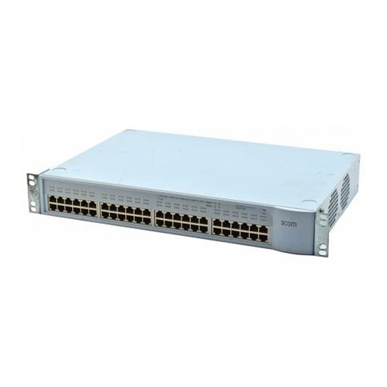
1: I 4300 HAPTER NTRODUCING THE UPER TACK WITCH Switch 4300 — Figure 1 Switch 4300 — front view Front View Detail Module Status LEDs Power LED Port Status LEDs Module Packet LEDs POST LED 3C17100 SuperStack 3 Switch 4300 Post S = Status Yellow = 10 Mbps... - Page 15 Switch 4300 — Front View Detail Table 5 LED behavior Color Indicates Port Status LEDs Packet Green Packets are being transmitted/received on the port. No packets are being transmitted/received on the port. Status Green A high speed (100 Mbps) link is present, and the port is enabled.
-
Page 16: Switch 4300 - Rear View Detail
1: I 4300 HAPTER NTRODUCING THE UPER TACK WITCH Switch 4300 — Rear Figure 2 Switch 4300 — rear view View Detail Redundant Power Supply Data Console Port System Socket Warning Label Console Switch 4300 48 Port (max) 19200,8,1,N 3C17100 Serial No XXX/XXXXXXXXXX MAC Addr: XXXXXXXXXXXX Module 2... -
Page 17: Default Settings
Default Settings Default Settings Table 6 shows the default settings for the Switch 4300. If you initialize the Switch, it is returned to these defaults. Table 6 Default Settings Feature Switch 4300 Port Status Enabled Port Speed 10/100 Mbps ports are auto-negotiated Duplex Mode All fixed 10BASE-T and 100BASE-TX ports are auto-negotiating... - Page 18 1: I 4300 HAPTER NTRODUCING THE UPER TACK WITCH...
-
Page 19: Installing The Switch
NSTALLING THE WITCH This chapter contains the information you need to install and set up the Switch 4300. It covers the following topics: Package Contents Choosing a Suitable Site Rack-mounting Placing Units On Top of Each Other The Power-up Sequence Solving Problems Indicated by LEDs Managing the Switch WARNING: Safety Information. -
Page 20: Package Contents
Water or moisture cannot enter the case of the Switch. Air-flow is not restricted around the Switch or through the vents in the side of the Switch. 3Com recommends that you provide a minimum of 25 mm (1 in.) clearance. -
Page 21: Rack-Mounting
Rack-mounting The air is as free from dust as possible. The unit is installed in a clean, air conditioned environment. No more than four Switch units are placed on top of one another, if the units are free-standing. Rack-mounting The Switch 4300 is 1.5U and will fit in most standard 19-inch racks. CAUTION: Disconnect all cables from the Switch before continuing. -
Page 22: Placing Units On Top Of Each Other
2: I HAPTER NSTALLING THE WITCH 4 Repeat steps 2 and 3 for the other side of the Switch. 5 Insert the Switch into the 19-inch rack and secure with suitable screws (not provided). Ensure that ventilation holes are not obstructed. 6 Connect network cabling. -
Page 23: Connecting A Redundant Power System
(MDI) or a cross-over cable (MDIX). 3Com recommends that you use Category 5 twisted pair cable — the maximum segment length for this type of cable is 100 m (328 ft). -
Page 24: Solving Problems Indicated By Leds
There are several different methods of accessing the management software to manage a Switch. These methods are explained in Chapter Even if you do not intend to actively manage the switch, 3Com recommends that you change the password to prevent unauthorized access to your network. See “Logging in as a Default... -
Page 25: Setting U P For Management
4300 Management Interface Reference Guide” on the CD-ROM that is supplied with the Switch. For information about solving problems when managing the Switch, refer to the Problem Solving section in the “SuperStack 3 Switch 4300 Management Interface Reference Guide” on the CD-ROM that accompanies the Switch. -
Page 26: Methods Of Managing A Switch
Switch from a terminal. SNMP management — You can manage a Switch using any Network Manager running the Simple Network Management Protocol (SNMP), such as 3Com Network Supervisor software. Figure 4 shows how each of these management methods can be used in a network. -
Page 27: Setting Up Web Interface Management
Setting Up Web Interface Management Setting Up Web You can access the web interface using a management workstation Interface connected to a Switch over an IP network. Management Choosing a Browser To display the web interface correctly, use one of the following Web browsers: ®... -
Page 28: Setting Up Command Line Interface Management
3: S HAPTER ETTING P FOR ANAGEMENT Setting Up You can access the command line interface using: Command Line A terminal or terminal emulator connected to the console port of a Interface Switch directly, or through a modem. Management A terminal or terminal emulator connected to a Switch over an IP network using Telnet. -
Page 29: Setting Up Over The Network
Setting Up SNMP Management Setting Up Over the To manage a Switch using the command line interface over a network using Telnet: Network 1 Set up the Switch with IP information. To do this: a Access the command line interface of the Switch through the console port. -
Page 30: Managing A Switch Over The Network
3: S HAPTER ETTING P FOR ANAGEMENT Managing a Switch To manage a Switch over the network, the Switch must be correctly Over the Network configured with the following IP information: An IP address — for more information, see “IP Addresses” below. -
Page 31: Subnets And Using A Subnet Mask
These bits in the mask are set to 0 if the device is to treat the bit as part of the device number. If you are unsure about what mask to use, 3Com suggests that you contact your network administrator. - Page 32 3: S HAPTER ETTING P FOR ANAGEMENT Table 9 Default Users User Default Name Password Access Level monitor monitor monitor — the user can view, but not change manageable parameters admin security — the user can access and change all manageable password) parameters CAUTION: To protect your Switch from unauthorized access, you must...
-
Page 33: Safety Information
AFETY NFORMATION You must read the following safety information before carrying out any installation or removal of components, or any maintenance procedures on the Switch 4300. WARNING: Warnings contain directions that you must follow for your personal safety. Follow all directions carefully. You must read the following safety information carefully before you install or remove the unit. -
Page 34: Important Safety Information
A: S PPENDIX AFETY NFORMATION Important Safety Installation and removal of the unit must be carried out by qualified Information personnel only. If installing the Switch 4300 in a stack with SuperStack II or SuperStack 3 units that are narrower than the 4300, the Switch 4300 unit must be installed below the narrower units. -
Page 35: L'information De Sécurité Importante
L’information de Sécurité Importante This unit operates under SELV (Safety Extra Low Voltage) conditions according to IEC 950. The conditions are only maintained if the equipment to which it is connected also operates under SELV conditions. France and Peru only: This unit cannot be powered from IT †... - Page 36 A: S PPENDIX AFETY NFORMATION Cordon électrique: Il doit être agréé ans le pays d'utilisation: Etats-Unis et Le cordon doit avoir reçu l'homologation des UL et un Canada certificat de la CSA Le cordon souple doit respecter, à titre minimum, les spécifications suivantes : calibre 18 AWG type SV ou SJ...
-
Page 37: Wichtige Sicherheitsinforma-Tionen
Wichtige Sicherheitsinforma-tionen AVERTISSEMENT: Points d’accès RJ-45. Ceux-ci sont protégés par des prises de données. Ils ne peuvent pas être utilisés comme prises de téléphone conventionnelles standard, ni pour la connection de l’unité à un réseau téléphonique central privé ou public. Raccorder seulement connecteurs de données RJ-45, systèmes de réseaux de téléphonie ou téléphones de réseaux à... - Page 38 A: S PPENDIX AFETY NFORMATION Der Betrieb dieses Geräts erfolgt unter den SELV-Bedingungen (Sicherheitskleinstspannung) gemäß IEC 950. Diese Bedingungen sind nur gegeben, wenn auch die an das Gerät angeschlossenen Geräte unter SELV-Bedingungen betrieben werden. WARNHINWEIS: RJ-45-Porte. Diese Porte sind geschützte Datensteckdosen.
-
Page 39: In Outs
OUTS Null Modem Cable 9-pin to RS-232 25-pin Switch 4300 PC/Terminal Cable connector: 9-pin female Cable connector: 25-pin male/female Screen Shell Screen only required if screen always required Ground Ground required for handshake PC-AT Serial Cable 9-pin to 9-pin Switch 4300 PC-AT Serial Port Cable connector: 9-pin female Cable connector: 9-pin female... -
Page 40: Modem Cable
B: P PPENDIX OUTS Modem Cable 9-pin to RS-232 25-pin Switch 4300 RS-232 Modem Port Cable connector: 9-pin female Cable connector: 25-pin male Screen Screen Shell Ground Ground RJ-45 Pin Pin assignments are identical for 10BASE-T and 100BASE-TX RJ-45 Assignments connectors Table 10 Pin assignments Pin Number... -
Page 41: Rj-45 Pin Assignments
RJ-45 Pin Assignments Table 11 Pin assignments Pin Number Signal Function Ports configured as MDIX Receive Data + Bidirectional Data B+ Receive Data - Bidirectional Data B- Transmit Data + Bidirectional Data A+ Not assigned Bidirectional Data A- Not assigned Bidirectional Data D+ Transmit Data Bidirectional Data D-... - Page 42 B: P PPENDIX OUTS...
- Page 43 –40 °C to +70 °C (–8 °F to 158 °F) Operating Humidity 10–95% relative humidity, non-condensing Standards EN60068 to 3Com schedule (Package testing: paras 2.1, 2.2, 2.30, and 2.32. Operational testing: paras 2.1, 2.2, 2.30 and 2.13). Safety Agency Certifications UL 1950, EN60950, CSA 22.2 No.
-
Page 44: Technical Specifications
C: T PPENDIX ECHNICAL PECIFICATIONS Standards Supported SNMP: Terminal Emulation: SNMP protocol (RFC 1517) Telnet (RFC 854) MIB-II (RFC 1213) Protocols Used for Administration: Bridge MIB (RFC 1493) UDP (RFC 768) Interface MIB (RFC 1573) IP (RFC 791) EtherLike-MIB (RFC 1643) ICMP (RFC 792) Remote Monitoring MIB (RFC 1757) TCP (RFC 793) -
Page 45: Technical Support
3Com recommends that you access the 3Com Corporation World Wide Web site. Online Technical 3Com offers worldwide product support 24 hours a day, 7 days a week, Services through the following online systems: World Wide Web site... - Page 46 3Com FTP Site Download drivers, patches, software, and MIBs across the Internet from the 3Com public FTP site. This service is available 24 hours a day, 7 days a week. To connect to the 3Com FTP site, enter the following information into...
- Page 47 Diagnostic error messages Details about recent configuration changes, if applicable Here is a list of worldwide technical telephone support numbers. These numbers are correct at the time of publication. Refer to the 3Com Web site for updated information. Country Telephone Number...
-
Page 48: Returning Products For Repair
PPENDIX ECHNICAL UPPORT Returning Products Before you send a product directly to 3Com for repair, you must first for Repair obtain an authorization number. Products sent to 3Com without authorization numbers will be returned to the sender unopened, at the sender’s expense. - Page 49 NDEX Numbers installing the Switch 19 3Com Knowledgebase Web Services 45 prerequisites 20 3Com URL 45 Internet addresses 30 InterNIC 31 access levels of default users 31 IP address 30 addresses obtaining 31 IP 30 IP information setting up 27...
-
Page 50: Returning Products For Repair
NDEX modem cable 40 null modem cable 39 technical support RJ45 40 3Com Knowledgebase Web Services 45 serial cable 39 3Com URL 45 pin-outs 39 network suppliers 46 ports product repair 48 console 16 power socket 16 powering-up a Switch 4300 22... - Page 51 EGULATORY OTICES FCC S TATEMENT This equipment has been tested and found to comply with the limits for a Class A digital device, pursuant to part 15 of the FCC rules. These limits are designed to provide reasonable protection against harmful interference when the equipment is operated in a commercial environment.