Komatsu PC350LC-8 Operation & Maintenance Manual
Hydraulic excavator
Hide thumbs
Also See for PC350LC-8:
- Shop manual (51 pages) ,
- Operation & maintenance manual (31 pages) ,
- Brochure (8 pages)
Table of Contents
Advertisement
Operation &
Maintenance Manual
PC350LC
PC350NLC
HYDRAULIC EXCAVATOR
SERIAL NUMBER
PC350LC-8
PC350NLC-8
PC350LCD-8
PC350NLCD-8
WARNING
Unsafe use of this machine may cause serious injury or
death. Operators and maintenance personnel must read
this manual before operating or maintaining this
machine. This manual should be kept inside the cab for
reference and periodically reviewed by all personel who
will come into contact with the machine.
- K50001
and up
- K50001
and up
- K50001
and up
- K50001
and up
-8
-8
UEAM007002
Advertisement
Table of Contents

Related Manuals for Komatsu PC350LC-8


Summary of Contents for Komatsu PC350LC-8
- Page 1 Operation & UEAM007002 Maintenance Manual PC350LC PC350NLC HYDRAULIC EXCAVATOR SERIAL NUMBER PC350LC-8 - K50001 and up PC350NLC-8 - K50001 and up PC350LCD-8 - K50001 and up PC350NLCD-8 - K50001 and up WARNING Unsafe use of this machine may cause serious injury or death.
-
Page 3: Foreword
FOREWORD... - Page 4 Keep this manual at the storage location for the Operation and Maintenance Manual given below so that all personnel involved in working on the machine can consult it periodically. In case this manual should be lost or damaged, immediately contact Komatsu or your Komatsu distributor to obtain a new copy.
-
Page 5: Foreword
FOREWORD SAFETY INFORMATION SAFETY INFORMATION To enable you to use this machine safely, safety precautions and labels are given in this manual and affixed to the machine to give explanations of situations involving potential hazards and of the methods of avoiding such situa- tions. - Page 6 Continuing improvements in the design of this machine can lead to changes in detail which may not be reflected in this manual. Consult Komatsu or your Komatsu distributor for the latest available information of your machine or for questions regarding information in this manual.
-
Page 7: Noise Emission Levels
FOREWORD SAFETY INFORMATION Noise emission levels Two labels indicating the machine noise level are affixed on the machine. q Sound pressure level at the operator’s station, measured according to ISO6396 (Dynamic test method, simulated working cycle). q Sound power level emitted by the machine, measured according to ISO 6395 (Dynamic test method, simulated working cycle). -
Page 8: Operating Condition
FOREWORD SAFETY INFORMATION Operating condition: (HYDRAULIC EXCAVATORS:) Excavating (Digging-loading-rotating-unloading-rotating). Guide to Reduce Vibration Levels on Machine The following guides can help an operator of this machine to reduce the whole body vibration levels: 1. Use the correct equipment and attachments. 2. -
Page 9: Introduction
FOREWORD INTRODUCTION INTRODUCTION This Komatsu machine is designed to be used mainly for the following work: q Digging work q Leveling work q Ditching work q Loading work q Demolition work See the section “RECOMMENDED APPLICATIONS (3-175)“ for further details. -
Page 10: Breaking-In The New Machine
BREAKING-IN THE NEW MACHINE NOTICE Your Komatsu machine has been thoroughly adjusted and tested before shipment from the factory. How- ever, operating the machine under full load before breaking the machine in can adversely affect the perfor- mance and shorten the machine life. -
Page 11: Product Information
FOREWORD PRODUCT INFORMATION PRODUCT INFORMATION When requesting service or ordering replacement parts, please inform your Komatsu distributor of the following items. PRODUCT IDENTIFICATION NUMBER (PIN)/MACHINE SERIAL NO. PLATE On the bottom right of the operator's cab The design of the nameplate differs according to the territory. -
Page 12: Service Meter Location
FOREWORD PRODUCT INFORMATION SERVICE METER LOCATION On top of the machine monitor 1-10... -
Page 13: Machine Serial Plate
MANUFACTURING YEAR MODEL MODEL SERIAL SERIAL No. MANUFACT. YEAR WEIGHT MASS ENGINE POWER ENGINE POWER Product Identification Number PRODUCT ID NUMBER Manufactured by Komatsu UK Ltd. MANUFACTURER for Komatsu Ltd.,Tokyo,Japan MANUFACTURER 205-00-K1291 Komatsu UK Ltd, Birtley, Co Durham, United Kingdom 1-11... -
Page 14: Table Of Contents
CONTENTS CONTENTS FOREWORD FOREWORD ................................. 1-2 SAFETY INFORMATION............................1-3 Noise emission levels ..........................1-5 Vibration levels............................1-5 Operating condition: .......................... 1-6 Guide to Reduce Vibration Levels on Machine.................. 1-6 INTRODUCTION..............................1-7 DIRECTIONS OF MACHINE ........................1-7 BREAKING-IN THE NEW MACHINE ......................1-8 PRODUCT INFORMATION .......................... - Page 15 CONTENTS OPERATION MACHINE VIEW ILLUSTRATIONS ........................3-2 OVERALL MACHINE VIEW........................3-2 CONTROLS AND GAUGES ........................3-3 DETAILED CONTROLS AND GAUGES......................3-5 MONITORING SYSTEM..........................3-5 Basic Operation of Machine Monitor....................3-6 Emergency Monitors........................3-11 Caution Monitors..........................3-13 Basic Check Monitors ........................3-16 Meter Display Portion ........................
- Page 16 CONTENTS MACHINE OPERATIONS AND CONTROLS....................3-120 BEFORE STARTING ENGINE ....................... 3-120 Walk-around Checks ........................3-120 Checks Before Starting ........................3-122 Adjustment............................. 3-130 Seat Belt ............................3-136 Operations Before Starting Engine ....................3-137 STARTING ENGINE ..........................3-139 AMBIENT TEMPERATURE RANGE FOR OPERATION ............... 3-142 AFTER STARTING ENGINE ........................
- Page 17 OIL ..............................4-4 FUEL..............................4-5 COOLANT AND WATER FOR DILUTION ..................4-5 GREASE............................4-6 CARRYING OUT KOWA (Komatsu Oil Wear Analysis) ..............4-6 STORING OIL AND FUEL......................... 4-7 FILTERS ............................4-7 EXPLANATION OF LUBRICATION CHART DECAL ................. 4-8 ELECTRIC SYSTEM MAINTENANCE ..................... 4-10...
- Page 18 CONTENTS WEAR PARTS ..............................4-11 WEAR PARTS LIST..........................4-11 RECOMMENDED FUEL, COOLANT, AND LUBRICANT ................. 4-12 RECOMMENDED BRANDS, RECOMMENDED QUALITY FOR PRODUCTS OTHER THAN KOMATSU GENUINE OIL............................4-14 TIGHTENING TORQUE SPECIFICATIONS ...................... 4-15 TIGHTENING TORQUE LIST ........................4-15 SAFETY CRITICAL PARTS ..........................4-16 SAFETY CRITICAL PARTS LIST ......................
- Page 19 CONTENTS REPLACE BREATHER ELEMENT IN HYDRAULIC TANK ............4-67 REPLACE HYDRAULIC TANK ADDITIONAL BREATHER ELEMENT .......... 4-68 EVERY 1000 HOURS MAINTENANCE....................4-69 REPLACE FUEL MAIN FILTER CARTRIDGE ................4-69 REPLACE HYDRAULIC OIL FILTER ELEMENT ................4-71 CHANGE OIL IN SWING MACHINERY CASE ................4-72 CHECK OIL LEVEL IN DAMPER CASE, ADD OIL .................
- Page 20 BEFORE STORAGE POSTURE WHEN LEAVING MACHINE ............6-37 TESTING AND ADJUSTING ......................6-37 PERODIC MAINTENANCE ......................6-38 PC350-8 WORKING RANGE (2-pc boom) ..................6-39 EXPLANATION OF LIFTING CAPACITY CHART..................6-40 PC350LC-8, PC350NLC-8 2 PIECE BOOM ................... 6-41 PC350LC-8 2 PIECE BOOM ......................6-41 1-18...
- Page 21 CONTENTS PC350NLC-8 2 PIECE BOOM......................6-42 TRANSPORTATION..........................6-43 SUPER LONG FRONT BOOM AND ARM......................6-44 OPERATION INSTRUCTION ........................6-44 WORKING MODES ..........................6-45 CHECKS BEFORE STARTING....................... 6-46 USING SUPER LONG FRONT ....................... 6-46 METHOD OF WORK ........................6-48 WHEN TRAVELLING ........................6-48 CONTROL LEVERS, PEDALS......................
- Page 22 CONTENTS OPERATING WORK EQUIPMENT ....................7-23 ATTACHMENT CONTROL......................7-25 RAISING WORK EQUIPMENT ....................... 7-26 WORKING RANGE AND USING RANGE OF BOOM ................7-27 INSTALLATION AND REMOVAL ........................7-30 DEMOLITION DIGGING BOOM INSTALLATION AND REMOVAL ............7-30 PROCEDURE FOR INSTALLATION AND REMOVAL OF DEMOLITION DIGGING EQUIPMENT.
-
Page 23: Safety
SAFETY WARNING Please read and make sure that you fully understand the precautions described in this manual and the safety labels on the machine. When operating or servicing the machine, always follow these precautions strictly. -
Page 24: Safety Information
SAFETY SAFETY INFORMATION SAFETY INFORMATION 2SAFETY INFORMATION ..........................2-2 2SAFETY LABELS ............................. 2-4 2LOCATION OF SAFETY LABELS ......................2-4 2SAFETY LABELS ............................2-5 2SAFETY INFORMATION ..........................2-13 2SAFETY RULES ..........................2-13 2IF PROBLEMS ARE FOUND ....................... 2-13 2WORKING WEAR AND PERSONAL PROTECTIVE ITEMS .............. 2-13 2FIRE EXTINGUISHER AND FIRST AID KIT .................. - Page 25 SAFETY SAFETY INFORMATION 2STARTING ENGINE WITH BOOSTER CABLES ................2-33 2TOWING ..............................2-34 2SAFETY RULES FOR TOWING ......................2-34 2LIFTING OBJECTS WITH BUCKET ......................2-35 2SAFETY RULES FOR LIFTING OBJECTS ..................2-35 SAFETY MAINTENANCE INFORMATION ...................... 2-36 2WARNING TAG ............................2-36 2KEEP WORK PLACE CLEAN AND TIDY ....................
-
Page 26: Safety Labels
If the labels are damaged, lost, or cannot be read properly, replace them with new ones. For details of the part numbers for the labels, see this manual or the actual label, and place an order with Komatsu distributor. -
Page 27: Safety Labels
SAFETY SAFETY LABELS SAFETY LABELS 1. (20Y-00-K2020) q Warnings for operation, inspection and maintenance q Improper operation and maintenance can cause serious injury or death. q Read the manual and labels before operation and mainte- nance. Follow instructions and warnings in manual and in labels on machine. - Page 28 SAFETY SAFETY LABELS q b. Always apply lock when leaving operator’s seat. q c. WARNING - No passengers No passengers allowed to ride on machine while it is mov- q d. WARNING - DANGER OF FALLING OBJECTS Do not operate where a danger of falling objects exists. Consult your dealer for fitting of FOPS protection...
- Page 29 SAFETY SAFETY LABELS q e. Caution for going close to electric cables. q An electrocution hazard if the machine is brought too near to electric power lines q Keep a safe distance from electric power lines. q f. Control levers operational function diagram. WARNING In order to prevent an accident resulting in injury or death caused by error-operation, confirm the machine motion...
- Page 30 SAFETY SAFETY LABELS (3) Caution when stowing front window (09803-A0481) q Sign indicates a hazard from falling window. q After raising window, be sure to lock it in place with lock pins. (4) Caution for high-temperature coolant and hydraulic oil (09653-A0481) q Never remove the cap when the engine is at operating (high) temperature.
- Page 31 SAFETY SAFETY LABELS (7) Caution for handling cable (09808-A0881) q Sign indicates an electric hazard from handling the cable. q Read manual for safe and proper handling. (8) Stop rotating parts when inspection and maintenance (09667-A0481) q Sign indicates a hazard of rotating parts, such as belt. q Turn off before inspection and maintenance.
- Page 32 SAFETY SAFETY LABELS (10) Caution against falling (09805-A0881) q There is the hazard of falling down. q Do not go close to the edge of the machine by mistake. (11) Caution against falling (09805-C0481) q Sign indicates a hazard of falling. q Do not step here!.
- Page 33 SAFETY SAFETY LABELS (13) Caution for use of hydraulic quick coupler piping system (20J-00-11271) q There is a danger of an exposed person being killed by fall- ing attachment. q Read the manual for safe operation. 14) (206-00-K1010) q Pump Control override switch and swing lock override switch q Read the operation manual before operation (15) Keeping out of working range area (20E-00-K1140)
- Page 34 SAFETY SAFETY LABELS (16) Prohibition of jump start (09842-A0481) q Start the engine only after sitting down in the operator’s seat. q Do not attempt to start the engine by short-circuiting the engine starting circuit. Such an act may cause a serious bodily injury or fire.
-
Page 35: Safety Information
SAFETY SAFETY INFORMATION SAFETY INFORMATION SAFETY RULES q Only trained and authorized personnel can operate and maintain the machine. q Follow all safety rules, precautions and instructions when operating or performing maintenance on the machine. q If you are under the influence of alcohol or medication, your ability to safely operate or repair your machine may be severely impaired putting yourself and everyone else on your jobsite in danger. - Page 36 SAFETY SAFETY INFORMATION SAFETY EQUIPMENT q Be sure that all guards and covers are in their proper position. Have guards and covers repaired immediately if they are damaged. q Understand the method of use of safety features and use them properly. q Never remove any safety features.
- Page 37 SAFETY SAFETY INFORMATION HANDRAILS AND STEPS To prevent personal injury caused by slipping or falling off the machine, always do as follows. q Use the handrails and steps marked by arrows in the dia- gram on the right when getting on or off the machine. q To ensure safety, always face the machine and maintain three-point contact (both feet and one hand, or both hands and one foot) with the handrails and steps (including the...
- Page 38 SAFETY SAFETY INFORMATION DO NOT GET CAUGHT IN ARTICULATED PORTION The clearance around the work equipment will change according to the movement of the link. If you get caught, this may lead to serious personal injury. Do not allow anyone to approach any rotating or telescoping part. BURN PREVENTION Hot coolant q To prevent burns from hot water or steam spurting out...
-
Page 39: Specifications
SAFETY SAFETY INFORMATION FIRE PREVENTION AND EXPLOSION PREVENTION q Fire caused by fuel or oil Fuel, oil, antifreeze, and window washer liquid are particu- larly flammable and can be hazardous. To prevent fire, always observe the following: q Do not smoke or use any flame near fuel or oil. q Stop the engine before refueling. - Page 40 No attempt should be made to repair these parts as this may have an adverse effect on component strength or durability. If such a repair is undertaken without authorisation from Komatsu there is a danger that a problem might occur that will lead to serious personal injury.
- Page 41 UNAUTHORIZED MODIFICATIONS If this machine is modified without permission from Komatsu, there is danger that problems may occur with safety and that this may lead to serious personal injury. Modifications may have an adverse effect on items such as machine strength and visibility.
- Page 42 SAFETY SAFETY INFORMATION WORKING ON LOOSE GROUND q Avoid traveling or operating your machine too close to the edge of cliffs, overhangs, and deep ditches. The ground may be weak in such areas. If the ground should collapse under the weight or vibration of the machine, there is a hazard that the machine may fall or tip over.
- Page 43 Komatsu distributor immedi- ately and ask for repairs to be carried out.
- Page 44 Do not allow other persons to approach during the opera- tion. q Always observe the rules and regulations for the work site and environmental standards. This machine does not use asbestos, but there is a danger that imitation parts may contain asbestos, so always use genuine Komatsu parts. 2-22...
-
Page 45: Safety Machine Operation
SAFETY SAFETY MACHINE OPERATION SAFETY MACHINE OPERATION STARTING ENGINE If there is a warning tag hanging from the work equipment con- trol lever, do not start the engine or touch the levers. CHECKS BEFORE STARTING ENGINE Carry out the following checks before starting the engine at the beginning of the day's work. q Remove all dirt from the surface of the window glass to ensure a good view. - Page 46 SAFETY SAFETY MACHINE OPERATION SAFETY RULES FOR STARTING ENGINE q Start and operate the machine only while seated. q Do not attempt to start the engine by short-circuiting the engine starting circuit. Such an act may cause a seri- ous bodily injury or fire. q When starting the engine, sound the horn as a warning.
-
Page 47: Operation
SAFETY SAFETY MACHINE OPERATION OPERATION CHECKS BEFORE OPERATION When carrying out the checks, move the machine to a wide area where there are no obstructions, and operate slowly. Do not allow anyone near the machine. q Always fasten your seat belt. q Check that the movement of the machine matches the display on the control pattern card. - Page 48 SAFETY SAFETY MACHINE OPERATION SAFETY RULES FOR TRAVELING q When traveling on level ground, keep the work equipment at a height of 40 to 50 cm from the ground. q If the work equipment blocks the view and it is difficult to travel in safety, raise the work equipment to a greater height.
- Page 49 SAFETY SAFETY MACHINE OPERATION q When traveling up a steep slope, extend the work equip- ment to the front to improve the balance, keep the work equipment approximately 20 to 30 cm above the ground, and travel at low speed. q When traveling downhill, lower the engine speed, keep the travel lever close to the neutral position, and travel at low speed.
- Page 50 SAFETY SAFETY MACHINE OPERATION q Do not excavate too deeply under the front of the machine. The ground under the machine may collapse and cause the machine to fall. q To make it easier to escape if there is any problem, set the tracks at right angles to the road shoulder or cliff with the sprocket at the rear when carrying out operations.
- Page 51 SAFETY SAFETY MACHINE OPERATION q Do not use the impact force of the work equipment for breaking work. There is a hazard of damage to the work equipment, or a hazard of serious personal injury being caused by flying pieces of broken materials, or of the machine tipping over due to reaction from the impact.
- Page 52 SAFETY SAFETY MACHINE OPERATION q When leaving the machine, set lock lever (1) to the LOCK position (L), then stop the engine. q Always close the operator's cab door, and use the key to lock all the equipment in order to prevent any unauthorized person from moving the machine.
-
Page 53: Transportation
SAFETY MACHINE OPERATION TRANSPORTATION The machine can be divided into parts for transportation, so when transporting the machine, please contact your Komatsu distributor to have the work carried out. LOADING AND UNLOADING When loading or unloading the machine, mistaken operation may bring the hazard of the machine tipping over or falling, so particular care is necessary. -
Page 54: Battery
SAFETY SAFETY MACHINE OPERATION BATTERY BATTERY HAZARD PREVENTION Battery electrolyte contains sulphuric acid, and batteries generate flammable hydrogen gas, which may explode. Mistaken handling can lead to serious injury or fire. For this reason, always observe the following precautions. q Do not use or charge the battery if the battery electrolyte level is below the LOWER LEVEL line. This may cause an explosion. -
Page 55: 2Starting Engine With Booster Cables
SAFETY SAFETY MACHINE OPERATION STARTING ENGINE WITH BOOSTER CABLES If any mistake is made in the method of connecting the booster cables, it may cause the battery to explode, so always do as follows. q When starting with a booster cable, carry out the starting operation with two workers (one worker sitting in the opera- tor's seat and the other working with the battery). -
Page 56: Towing
SAFETY SAFETY MACHINE OPERATION TOWING SAFETY RULES FOR TOWING Serious injury or death could result if a disabled machine is towed incorrectly or if there is a mistake in the selec- tion or inspection of the wire rope. For towing, see “TOWING THE MACHINE (3-203)“. q Always check that the wire rope used for towing has ample strength for the weight of the machine being towed. -
Page 57: Lifting Objects With Bucket
SAFETY SAFETY MACHINE OPERATION LIFTING OBJECTS WITH BUCKET SAFETY RULES FOR LIFTING OBJECTS q Determine the signals to be used and place a signalman in position. q To prevent the machine from tipping over or falling, carry out the operation on flat ground. q To prevent the danger of contact with a raised load or the danger from a falling load, do not allow any worker inside the area. -
Page 58: Safety Maintenance Information
SAFETY SAFETY MAINTENANCE INFORMATION SAFETY MAINTENANCE INFORMATION WARNING TAG q Always attach the “DO NOT OPERATE“ warning tag to the work equipment control lever in the operator's cab to alert others that you are performing service or maintenance on the machine. Attach additional warning tags around the machine if necessary. -
Page 59: 2Stop Engine Before Carrying Out Maintenance
SAFETY SAFETY MAINTENANCE INFORMATION STOP ENGINE BEFORE CARRYING OUT MAINTENANCE q Stop the machine on firm, level ground. q Select a place where there is no hazard of falling rocks or landslides, or of flooding if the land is low. q Lower the work equipment completely to the ground and stop the engine. -
Page 60: 2Proper Tools
Do not hit or roll the accumulator, or subject it to any impact. q When disposing of the accumulator, the gas must be released. Please contact your Komatsu distributor to have this work performed. PERSONNEL Only authorized personnel can service and repair the machine. Do not allow unauthorized personnel into the area. -
Page 61: 2Attachments
SAFETY SAFETY MAINTENANCE INFORMATION ATTACHMENTS q Appoint a leader before starting removal or installation operations for attachments. q Place attachments that have been removed from the machine in a stable condition so that they do not fall. And take steps to prevent unauthorized persons from entering the storage area. -
Page 62: 2Removing Battery Terminals
If it is disassembled by mistake, the spring will fly out and cause serious injury. When it becomes necessary to disassemble it, ask your Komatsu distributor to do the work. SAFETY RULES FOR HIGH-PRESSURE OIL The hydraulic system is always under internal pressure. -
Page 63: 2Precaution For High Fuel Pressure
If any loose bolts are found, stop work and tighten to the specified torque. If any damaged hoses are found, stop operations immediately and contact your Komatsu distributor. Replace the hose if any of the following problems are found. -
Page 64: 2Waste Materials
SAFETY SAFETY MAINTENANCE INFORMATION WASTE MATERIALS To prevent pollution, pay careful attention to the method of disposing of waste materials. q Always put oil drained from your machine in containers. Never drain oil directly onto the ground or dump into the sewage system, rivers, the sea, or lakes. - Page 65 OPERATION WARNING Please read and make sure that you understand the SAFETY section before reading this section.
-
Page 66: Operation
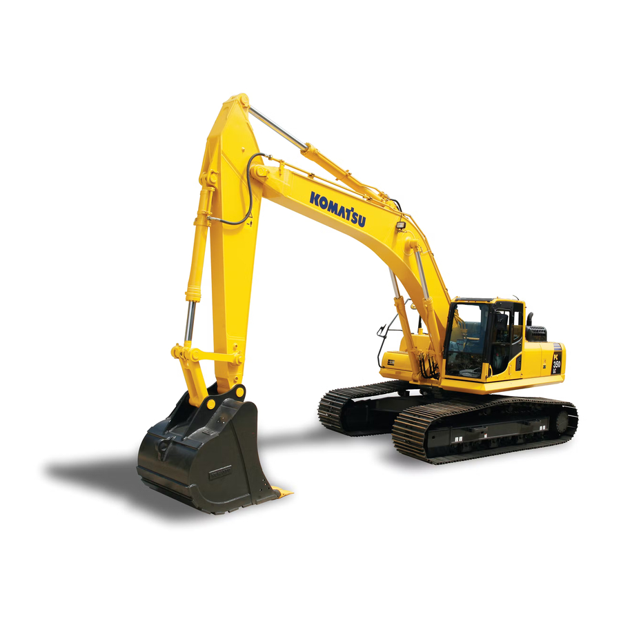
OPERATION MACHINE VIEW ILLUSTRATIONS MACHINE VIEW ILLUSTRATIONS OVERALL MACHINE VIEW Bucket Boom cylinder Bucket cylinder Sprocket Track frame Arm cylinder Track shoe Boom (10) Idler... -
Page 67: Controls And Gauges
OPERATION MACHINE VIEW ILLUSTRATIONS CONTROLS AND GAUGES Front of levers Radio (18) Attachment control pedal (if equipped) Lock lever (19) Room lamp switch Left work equipment control lever (20) Emergency pump drive switch One-touch power max. switch (21) Swing parking brake release switch Travel pedals (22) Lower wiper switch Travel levers... - Page 68 OPERATION MACHINE VIEW ILLUSTRATIONS Machine monitor AA: Screen for standard BB: Screen with all lamps lighted up CC: Maintenance time warning screen Wiper switch (16) Window washer switch Buzzer cancel switch (17) Air conditioner control switches Auto-deceleration switch (18) Engine oil pressure monitor Engine coolant temperature monitor (19) Charge level monitor Engine coolant temperature gauge...
-
Page 69: Detailed Controls And Gauges
OPERATION DETAILED CONTROLS AND GAUGES DETAILED CONTROLS AND GAUGES The following is an explanation of devices needed for operating the machine. To perform suitable operations correctly and safely, it is important to completely understand methods of operating the equipment, and the meanings of the displays. MONITORING SYSTEM AA: Screen for standard BB: Screen with all lamps lighted up... -
Page 70: Basic Operation Of Machine Monitor
OPERATION DETAILED CONTROLS AND GAUGES Basic Operation of Machine Monitor Starting Engine When Situation is Normal q When the starting switch is turned to the ON position, the opening screen GG is displayed. q After the opening screen GG is displayed for 2 seconds, the screen switches to the check before starting screen DD. - Page 71 OPERATION DETAILED CONTROLS AND GAUGES REMARK When the engine is started, the battery voltage may suddenly drop depending on the temperature and the battery condition. If this happens, the display on the machine monitor may momentarily go out, but this does not indicate any abnormality.
- Page 72 OPERATION DETAILED CONTROLS AND GAUGES If There Is Abnormality When Starting Engine q If there is any abnormality when starting the engine, the check before starting screen DD changes to the main- tenance interval warning screen CC, warning screen FF, or error screen EE. q After displaying the check before starting screen DD for 2 seconds, the screen changes to the maintenance interval warning screen CC.
- Page 73 OPERATION DETAILED CONTROLS AND GAUGES If Any Abnormality Occurs During Operation q If any abnormality occurs during operation, the standard screen BB changes to warning screen FF-(1) or the error screen EE. q After displaying warning screen FF-(1) for 2 seconds, the screen automatically changes to warning screen FF- (2).
- Page 74 OPERATION DETAILED CONTROLS AND GAUGES REMARK The colors lighting up the monitors related to the emergency stop items, caution items, and basic check items are as follows. AA: Screen for standard BB: Screen with all lamps lighted up CC: Maintenance time warning screen Color when monitor lights up Type of monitor When...
-
Page 75: Emergency Monitors
OPERATION DETAILED CONTROLS AND GAUGES Emergency Monitors CAUTION If the monitor lights up red, stop the engine immediately or run at low idle, check applicable location, then perform necessary actions. These items should be observed while the engine is running. If there is a problem, the monitor for the abnormal location lights up red and buzzer sounds, perform action immediately. - Page 76 OPERATION DETAILED CONTROLS AND GAUGES Hydraulic Oil Temperature Monitor This monitor (2) warns the operator that the hydraulic oil tem- perature has risen. If the hydraulic oil temperature becomes abnormally high, abnormality display (C) is shown. Stop operations and stop the engine or run it at low idling until the monitor changes to normal display (B).
-
Page 77: Caution Monitors
OPERATION DETAILED CONTROLS AND GAUGES Caution Monitors CAUTION If the warning monitor lights up red, stop operations as soon as possible and perform inspection and maintenance of the applicable location. If the warning is ignored, it may lead to failure. These are items that should be observed while the engine is running. - Page 78 OPERATION DETAILED CONTROLS AND GAUGES Hydraulic Oil Temperature Monitor If this monitor (2) shows low-temperature display (A), carry out the warm-up operation. For details, see “Hydraulic Equipment Warm Up (3-145)“. Carry out the warm-up operation for the hydraulic equipment until monitor (2) shows normal display (B). Display (A) at low temperatures: Monitor background (D) is white Display (B) at correct temperatures: Monitor background (D) is...
- Page 79 OPERATION DETAILED CONTROLS AND GAUGES Water Separator Monitor This monitor (6) warns the operator when water has accumu- lated inside the water separator. For details of the method of draining the water from the water separator, see “Check for Water and Sediment in Water Sepa- rator, Drain Water (3-123)“.
-
Page 80: Basic Check Monitors
OPERATION DETAILED CONTROLS AND GAUGES Basic Check Monitors CAUTION These monitors do not guarantee the condition of the machine. Do not simply rely on the monitor when carrying out checks before starting (daily inspection). Always get off the machine and check each item directly. Displays basic items among the check before starting items that must be checked before starting the engine. - Page 81 REMARK For details of the method of confirming the maintenance inter- val, see “Maintenance Selector Switch (3-42)“. If it is desired to change settings for the maintenance interval, have your Komatsu distributor change the settings. 3-17...
-
Page 82: Meter Display Portion
OPERATION DETAILED CONTROLS AND GAUGES Meter Display Portion Pilot display Gauge and Meter Engine pre-heating monitor (10) Engine coolant temperature gauge Swing lock monitor (11) Hydraulic oil temperature gauge Wiper monitor (12) Fuel gauge Auto-deceleration monitor (13) Service meter, clock Working mode monitor (14) ECO gauge Travel speed monitor... - Page 83 OPERATION DETAILED CONTROLS AND GAUGES Swing Lock Monitor This monitor (2) informs the operator that the swing lock is being actuated. Actuated: Lights up When the swing lock switch is turned ON (ACTUATED), the monitor lamp lights up. This lamp lights up when the swing parking brake release switch is set to the FREE position.
- Page 84 OPERATION DETAILED CONTROLS AND GAUGES Working Mode Monitor This monitor (5) displays the setting of the working mode. The monitor display is as follows according to the operation of the working mode switch. P: P mode (for heavy-load operations) E: E mode (for operations with emphasis on fuel consumption) L: L mode (for fine control operations) B: B mode (for breaker operations) ATT: ATT mode (for crusher operations)
- Page 85 OPERATION DETAILED CONTROLS AND GAUGES Air Conditioner Monitor This monitor (8) displays the working status of the air condi- tioner. Monitor lighted up: Air conditioner ON Monitor off: Air conditioner OFF Idle Stop Guidance If the levers are not operated for more than five minutes, and the engine is idling, the idling stop message is displayed on the monitor.
- Page 86 OPERATION DETAILED CONTROLS AND GAUGES Gauges and Meter Engine Coolant Temperature Gauge This meter (10) shows the engine coolant temperature. During normal operations, the indicator should be in the green range. If the indicator goes beyond red range (A) during opera- tions, the overheat prevention system is actuated.
- Page 87 OPERATION DETAILED CONTROLS AND GAUGES Hydraulic Oil Temperature Gauge This meter (11) shows the hydraulic oil temperature. During normal operations, the indicator should be in the green range. If the indicator enters the red range (A) during operations, the hydraulic oil temperature is 102°C or more. Run the engine at low idling or stop it and wait for the hydraulic oil temperature to go down.
- Page 88 OPERATION DETAILED CONTROLS AND GAUGES Service Meter, Clock This meter (13) shows the total hours of operation of the machine or the present time. When the engine is running, the service meter advances even if the machine is not moving. The service meter advances 1 for every hour that the machine is working, regardless of the engine speed.
- Page 89 OPERATION DETAILED CONTROLS AND GAUGES ECO Gauge This gauge (14) shows the working load status. When the gauge is in green range A, the work load is light to medium. When the gauge is in orange range B), the load is heavy.
-
Page 90: Monitor Switches Portion
OPERATION DETAILED CONTROLS AND GAUGES Monitor Switches Portion Working mode selector switch Window washer switch Auto-deceleration switch Buzzer cancel switch Travel speed selector switch Function switches Wiper switch Air conditioner switch Working Mode Selector Switch Use this switch (1) to set the movement or power of the work equipment. - Page 91 If you press F5 (No), the system starts up in E mode. q If you want to have automatic setting of the P, E, L, B or ATT mode when starting (optional default setting), please ask your Komatsu distributor to change the setting. 3-27...
- Page 92 OPERATION DETAILED CONTROLS AND GAUGES Procedure for operation 1. If working mode selector switch (1) is pressed, the Working Mode screen is displayed on the monitor. 2. Press function switches F3 or F4 at the bottom of the screen or working mode selector switch (1) to change the mode selection one at a time.
- Page 93 OPERATION DETAILED CONTROLS AND GAUGES REMARK When setting the working mode to B mode, to ensure safety, the buzzer sounds and at the same time, the message in the illustration on the right is displayed. When setting to the breaker mode, always press function switch F6. q If function switch F5 is pressed, the breaker mode is not set, and the screen returns to working mode selection screen.
- Page 94 OPERATION DETAILED CONTROLS AND GAUGES Auto-deceleration Switch If the control levers are at neutral, this switch (2) automatically lowers the engine speed and turns on the function to reduce fuel consumption. Auto-deceleration monitor ON: Auto-deceleration ON Auto-deceleration monitor OFF: Auto-deceleration OFF Each time the switch is pressed, the auto-deceleration is switched between ON and OFF.
- Page 95 OPERATION DETAILED CONTROLS AND GAUGES Travel Speed Selector Switch WARNING q When loading or unloading from a trailer, always travel at low speed (with travel speed selector switch (3) at the Lo position). Never operate travel speed selector switch (3) while loading or unloading. q If the travel speed is switched between Hi and Lo when the machine is traveling, the machine may deviate to one side, even when traveling in a straight line.
- Page 96 OPERATION DETAILED CONTROLS AND GAUGES Wiper Switch This switch (4) actuates the front window wiper. Each time the switch is pressed, it changes ON → INT → stop (OFF). Wiper monitor INT lighted up: Wiper operates intermittently Wiper monitor ON lighted up: Wiper operates continuously Wiper monitor OFF: Wiper stops REMARK Each time wiper switch (4) is pressed, the mode is displayed in...
- Page 97 OPERATION DETAILED CONTROLS AND GAUGES Window Washer Switch This switch (5) is kept continuously pressed, window washer fluid is sprayed out on the front glass. When the switch is released, the spray stops. q If switch (5) is kept pressed when the wiper is stopped, the window washer fluid will spray, and at the same time, the wiper will be actuated continuously.
- Page 98 OPERATION DETAILED CONTROLS AND GAUGES Function Switches Function switches (7) consist of 6 switches (F1 to F6). The function of each switch differs according to the content of each screen. When the monitor display shows the standard screen, the func- tions are displayed as follows.
-
Page 99: Handling Function Switches
F3 is not displayed. Even if switch F3 is pressed, the screen will not switch to the camera screen display. q A maximum of three cameras can be installed. q If you want to install a camera, please consult your Komatsu distributor. 3-35... - Page 100 OPERATION DETAILED CONTROLS AND GAUGES Operations on Camera 1 Image Display Screen The following explanation describes the method of operation when it is desired to display only one camera screen on the monitor. q On the standard screen, if switch F3 is pressed, the image display screen is displayed.
- Page 101 OPERATION DETAILED CONTROLS AND GAUGES Operation of Image Display Screen When Two Camera Screens are Shown Simultaneously. The following explanation describes the method of operation when it is desired to display two camera screens at the same time on the monitor. q On the No.
- Page 102 OPERATION DETAILED CONTROLS AND GAUGES Other Mode Operations When Displaying Camera Image q Even during the camera display, it is possible to operate other modes. q The air conditioner can be operated. If the air conditioner switch is operated, the screen switches to the air conditioner control screen.
- Page 103 OPERATION DETAILED CONTROLS AND GAUGES When the travel speed mode is changed, the screen returns to the standard screen. To display the camera image, press switch F3 again. q Press the auto-deceleration switch to turn the auto-decel- eration function ON/OFF. Even if the auto-deceleration switch is pressed, the camera image display screen does not switch to another screen.
- Page 104 OPERATION DETAILED CONTROLS AND GAUGES Action When Warning is Generated When Displaying Camera Image q If an error or alarm occurs while the camera image is being displayed, the error monitor or alarm monitor is displayed at the top left of the screen and flashes. q If the error monitor or alarm monitor is displayed, press switch F6, return to the standard screen, and check the content of the error or alarm display.
- Page 105 OPERATION DETAILED CONTROLS AND GAUGES Service Meter/Clock Display Selector Switch On the standard screen, it is possible to press switch F4 to switch the service meter and clock display at the top of the monitor display. q When the time is being displayed, press switch F4 to switch to the service meter display.
- Page 106 OPERATION DETAILED CONTROLS AND GAUGES Maintenance Selector Switch When switch F5 is pressed on the standard screen, the monitor display screen switches to the maintenance mode screen. The items on the maintenance display are as follows. Engine oil change Engine oil filter change Fuel main filter change 1000 Fuel pre-filter change...
- Page 107 If the time remaining until maintenance becomes 0 hours, the remain- ing time display is highlighted in red. q If you want to change the setting for the maintenance inter- val, please consult your Komatsu distributor. 3-43...
- Page 108 OPERATION DETAILED CONTROLS AND GAUGES Operations on Maintenance Interval Reset Screen On the maintenance list screen, if switch F6 is kept pressed for at least 1.5 seconds, the screen changes to the maintenance time reset screen. Reset the remaining time on this screen. 1.
- Page 109 OPERATION DETAILED CONTROLS AND GAUGES User Mode Selector Switch When the switch F6 is pressed, the monitor display screen switches to the setting mode screen for the machine. q On the User Menu screen, it is possible to carry out the fol- lowing operations with switches F3 to F6.
- Page 110 OPERATION DETAILED CONTROLS AND GAUGES q The following items can be set. a: Breaker/attachment setting (machines ready for installation of attachment) b: Message display (machines equipped with KOMTRAX) c: Screen adjustment d: Clock adjustment e: Language selection f: Economy mode adjustment The operation for setting a to f is as follows.
- Page 111 OPERATION DETAILED CONTROLS AND GAUGES Changing Breaker Mode Setting 1. On the standard screen, press switch F6. 2. Select Breaker/Attachment Settings on the user menu, then press switch F6. Screen for machine with 1 Attachment Line Screen for machine with 2 Attachment Lines 3-47...
- Page 112 OPERATION DETAILED CONTROLS AND GAUGES 3. On the working mode selection screen shown on the right, select B Breaker and press switch F6. q On the working mode selection screen shown on the right, it is possible to carry out the following operations with switches F3 to F6.
- Page 113 OPERATION DETAILED CONTROLS AND GAUGES On the Breaker Select Menu screen, it is possible to carry out the following operations with switches F3 - F6. F3: Moves to next item (1 line down). F4: Moves to previous item (1 line up). F5: Returns to previous screen.
- Page 114 OPERATION DETAILED CONTROLS AND GAUGES 2. On the Breaker Select screen, select one of the two set values for the oil flow, then press switch F6. q The default values for the flow setting are both set to 230 liter/min, as shown in the illustration on the right. To select the oil flow setting, follow the procedure given in “Changing breaker flow setting (3-51)“.
- Page 115 OPERATION DETAILED CONTROLS AND GAUGES Changing breaker flow setting 1. Select breaker flow setting (b) on the Breaker Select Menu screen, then press switch F6. 2. On the Breaker Oil Flow Setting screen, select one of the two set values for the oil flow, then press switch F6. q The default values for the oil flow setting are both set to 230 liter/min, as shown in the illustration on the right.
- Page 116 OPERATION DETAILED CONTROLS AND GAUGES q On the Breaker Select Menu and Breaker Oil Flow Setting screen, it is possible to carry out the following operations with switches F3 - F6. F3: Moves to next item (1 line down). F4: Moves to previous item (1 line up). F5: Returns to previous screen.
- Page 117 OPERATION DETAILED CONTROLS AND GAUGES Changing Attachment Mode Setting 1. On the standard screen, press switch F6. 2. Select Breaker/Attachment Settings on the user menu, then press switch F6. Screen for machine with 1 Attachment Line Screen for machine with 2 Attachment Lines 3-53...
- Page 118 OPERATION DETAILED CONTROLS AND GAUGES 3. On the working mode selection screen shown on the right, select ATT 2-Way Attachment, then press switch F6. q On the working mode selection screen shown on the right, it is possible to carry out the following operations with switches F3 to F6.
- Page 119 OPERATION DETAILED CONTROLS AND GAUGES On the 2-Way Attachment Select Menu screen, it is possible to carry out the following operations with switches F3 - F6. F3: Moves to next item (1 line down). F4: Moves to previous item (1 line up). F5: Returns to previous screen.
- Page 120 OPERATION DETAILED CONTROLS AND GAUGES 2. On the 2-Way Attachment Select Menu, select one of the two set values for the oil flow, then press switch F6. q The default values for the oil flow setting are both set to 530 liters/min, as shown in the illustration on the right.
- Page 121 OPERATION DETAILED CONTROLS AND GAUGES Changing attachment flow setting 1. Select 2-Way Attachment Oil Flow Setting (b) on the 2-Way Attachment Select menu screen, then press switch F6. 2. On the 2-Way Attachment Select Oil Flow Setting screen, select one of the two set values for the oil flow, then press switch F6.
- Page 122 OPERATION DETAILED CONTROLS AND GAUGES q On the 2-Way Attachment Select Menu screen and 2-Way Attachment Select Menu screen, it is possible to carry out the following operations with switches F3 - F6. F3: Moves to next item (1 line down). F4: Moves to previous item (1 line up).
- Page 123 OPERATION DETAILED CONTROLS AND GAUGES 1. Attachment 2 Setting Note - If installing 2nd attachment line as a field kit ask distribu- tor to change monitor setting to allow 2 attachments (as shown below). On machines equipped with 2 attachment lines it is possible on the attachment 2 settings menu to adjust the oil flow in ATT mode to match the attachment installed.
- Page 124 OPERATION DETAILED CONTROLS AND GAUGES On the 2-Way Attachment Select Menu screen, it is possible to carry out the following operations with switches F3 - F6. F3: Moves to next item (1 line down). F4: Moves to previous item (1 line up). F5: Returns to user menu screen.
- Page 125 OPERATION DETAILED CONTROLS AND GAUGES Changing attachment 2 flow setting 1. Select 2-Way Attachment Oil Flow Setting (b) on the 2-Way Attachment Select menu screen, then press switch F6. 2. On the 2-Way Attachment Select Oil Flow Setting screen, select one of the two set values for the oil flow, then press switch F6.
- Page 126 OPERATION DETAILED CONTROLS AND GAUGES 3. On the 2-Way Attachment Oil Flow Setting menu, it is pos- sible to change the oil flow setting. Q After using switches F3 or F4 to change to a suitable oil flow, press switch F6 to accept the change in the oil flow and return to the previous screen.
- Page 127 DETAILED CONTROLS AND GAUGES Message Display (Machines equipped with KOMTRAX) On machines equipped with KOMTRAX, it is possible to see the messages from your Komatsu distributor on this message display menu. REMARK At present, there is no territory where it is possible to the use the message service.
- Page 128 OPERATION DETAILED CONTROLS AND GAUGES Adjusting Screen Use this screen adjustment menu to adjust the brightness, con- trast, and back light of the screen. 1. On the standard screen, press switch F6. 2. Select screen adjustment on the user menu, then press switch F6.
- Page 129 OPERATION DETAILED CONTROLS AND GAUGES 3. Select item to be adjusted (a) or (b) from the selection menu screen for screen adjustment, then press switch F6. The screen switches to the setting screen for the selected item. (a): Standard screen adjustment (b): Camera screen adjustment (only machines equipped with camera) q On the mode selection screen shown on the right, it is...
- Page 130 OPERATION DETAILED CONTROLS AND GAUGES On the screen for Items 1) and 2), it is possible to carry out the following operations with switches F2 to F6. F2: Resets all adjusted values to default value F3: Indicator of selected item moves 1 segment to left. F4: Indicator of selected item moves 1 segment to right.
- Page 131 OPERATION DETAILED CONTROLS AND GAUGES Clock Adjustment On this clock adjustment menu, it is possible to change the set- ting of the clock displayed on the pilot monitor of the standard display. 1. On the standard screen, press switch F6. 3-67...
- Page 132 OPERATION DETAILED CONTROLS AND GAUGES 2. Select “Clock Adjustment“ on the user menu, then press switch F6. The screen switches to the time adjustment selection menu screen. q The following three items can be changed. (a) Clock setting (b) 12/24 hour display mode (c) Daylight saving time 3-68...
- Page 133 OPERATION DETAILED CONTROLS AND GAUGES 3. On the clock adjustment selection screen, it is possible to carry out the following operations with switches F3 to F6. q Time Adjust the hour setting. 1) If “Time“ (a) is not highlighted in yellow, press switch F6 to highlight “Time“...
- Page 134 OPERATION DETAILED CONTROLS AND GAUGES 2) When minute display (c) is highlighted in orange, operate the switches as follows to adjust minute display (c). If it is not necessary to change the minute setting, press switch F6. If the time has been changed, always press switch F6.
- Page 135 OPERATION DETAILED CONTROLS AND GAUGES q Daylight Saving Time (Summer time) 1) If daylight saving time is turned ON (a), the clock display becomes 1 hour earlier. If daylight saving time is turned OFF (b), the clock display returns to the set time. The selected display mode is highlighted in green.
- Page 136 OPERATION DETAILED CONTROLS AND GAUGES Language Selection On this language selection menu, it is possible to select the language used on the monitor display. q The languages that can be selected are as follows. Japanese, English, Chinese, French, Spanish, Portuguese, Italian, German, Russian, Turkish, Indonesian, Thai 1.
- Page 137 OPERATION DETAILED CONTROLS AND GAUGES 3. Select the language to use for the display, then press switch F6. The screen display changes to the selected lan- guage. q On the language selection screen, it is possible to carry out the following operations with switches F3 to F3: Moves to item below.
- Page 138 OPERATION DETAILED CONTROLS AND GAUGES 2. Select “Economy Mode Adjustment“ on the user menu, then press switch F6. The screen switches to the economy mode adjustment selection menu screen. 3. Select the desired E mode from the economy mode adjust- ment selection menu.
-
Page 139: Switches
OPERATION DETAILED CONTROLS AND GAUGES SWITCHES Front of levers Starting switch (12) Cigarette lighter Fuel control dial (13) Room lamp Lamp switch (14) Emergency pump drive switch Swing lock switch (15) Swing parking brake release switch Machine push-up switch (16) Quick coupler switch Lower wiper (17) Quick coupler switch Heated seat... - Page 140 OPERATION DETAILED CONTROLS AND GAUGES Starting Switch Starting switch (1) is used to start or stop the engine. (A): OFF position The key can be inserted or withdrawn. Switches for the electri- cal system (except room lamp), are all turned off and the engine is stopped.
- Page 141 OPERATION DETAILED CONTROLS AND GAUGES Swing Lock Switch WARNING q When not using the swing operation, e.g. when traveling, put the swing lock switch to the OFF posi- tion. q On slopes, even when the swing lock switch is at the ON position, the weight of the work equipment may cause the upper structure to swing if the swing control lever is operated in the downhill direction.
- Page 142 OPERATION DETAILED CONTROLS AND GAUGES Roof Wiper Switch This switch (8) is used to turn on the roof wiper and to operate the washer. The switch has 3 positions: (a) ON...is with the rear end of the switch down. The wiper is (b) ON..is with the rear end of the switch pressed and held down.
- Page 143 OPERATION DETAILED CONTROLS AND GAUGES One-touch Power Max Switch Use this switch (11) on the left control lever to actuate the power max. system Press it once (single click) and keep it pressed. In P and E modes, the power max function can be actuated for a maxi- mum of only 8.5 seconds.
- Page 144 OPERATION DETAILED CONTROLS AND GAUGES This switch (14) is used to make it possible to carry out opera- tions temporarily if any problem should occur in the pump con- trol system (when the display shows “E02“). (a) EMERGENCY: When abnormal (move switch up) (b) NORMAL: When normal (move switch down) If the display shows “E02“, move the switch up to make it possi- ble to carry out work.
- Page 145 OPERATION DETAILED CONTROLS AND GAUGES Quick Coupler Switches To operate the Quick Coupler circuit switches (16) on the RHS console and (17) on the LH PPC lever must be operated together. Refer to "Hydraulic Quick Coupler"OPERATION (PAGE 6-4)" " for an explanation of these switches operation.
-
Page 146: Control Levers And Pedals
OPERATION DETAILED CONTROLS AND GAUGES CONTROL LEVERS AND PEDALS Lock lever Left work equipment control lever Travel levers (with auto-deceleration system) (with pedal and auto-deceleration system) Right work equipment control lever (with auto-deceleration system) Lock Lever WARNING q When leaving the operator's compartment, set the lock lever securely to the LOCK position. If the lock lever is not at the LOCK position and the control levers or control pedals are touched by mistake, it may lead to serious personal injury. - Page 147 OPERATION DETAILED CONTROLS AND GAUGES Travel Levers WARNING q Do not rest your foot on the pedal during operations. If the pedal is depressed by mistake, the machine may suddenly move and cause a serious accident. Be extremely careful when operating the pedal for travel or steering operations.
- Page 148 OPERATION DETAILED CONTROLS AND GAUGES Work Equipment Control Lever Left work equipment control lever (3) is used to operate the arm and upper structure. Arm operation (a) Arm OUT (b) Arm IN Swing operation (c) Swing to right (d) Swing to left N (Neutral) : The upper structure and arm are held in position and do not move.
-
Page 149: Sun Roof
OPERATION DETAILED CONTROLS AND GAUGES SUN ROOF WARNING When leaving the operator's seat, set the lock lever securely to the LOCK position. If the lock lever is at the FREE position and the control levers or control pedals is touched by mistake, this may lead to a serious accident. -
Page 150: Windshield
OPERATION DETAILED CONTROLS AND GAUGES WINDSHIELD WARNING q When opening or closing the front window, bottom window, or door, always set the lock lever to the LOCK position. If the lock lever is at the FREE position and the control levers or control pedals is touched by mistake, this may lead to a serious accident. - Page 151 OPERATION DETAILED CONTROLS AND GAUGES 4. Hold 2 grips (A) on the left and right top sides of the front window, and pull the 2 levers (B) to release the locks at the top of the front window. The top of the front window will come out.
- Page 152 OPERATION DETAILED CONTROLS AND GAUGES 5. Hold lower knob (C) with your left hand from inside the operator's cab, and with your right hand, grip top knob (D), pull it up, and push it against lock catch (E) at the rear of the cab securely to lock the window.
- Page 153 OPERATION DETAILED CONTROLS AND GAUGES Closing WARNING When closing the window, lower it slowly and be careful not to get your hand caught. 1. Stop the machine on level ground, lower the work equipment completely to the ground, then stop the engine. 2.
- Page 154 OPERATION DETAILED CONTROLS AND GAUGES 5. When the bottom of the window reaches the top of the bot- tom window, push the top of the window to the front to push it against left and right lock catches (G) and engage the lock.
- Page 155 OPERATION DETAILED CONTROLS AND GAUGES Removing Lower Windshield 1. Open the front window, then hold grip (1), pull up, and remove the bottom window. q If sand or dust is collected at the bottom of the front win- dow, it will be difficult to remove the window. In addition, when stowing, the sand and dust stuck to the glass will be carried inside the cab.
-
Page 156: Emergency Escape Hammer
OPERATION DETAILED CONTROLS AND GAUGES EMERGENCY ESCAPE HAMMER CAUTION If it is necessary to break the window glass with the hammer, be extremely careful not to injure yourself on the flying pieces of broken glass. To prevent injury, remove the broken pieces of glass remaining in the frame before escaping through the window. -
Page 157: Cap With Lock
OPERATION DETAILED CONTROLS AND GAUGES CAP WITH LOCK Use the starting switch key to open and close the locks on the caps and covers. For details of the locations of the caps and covers with locks, see “LOCKING (3-183)“. Insert the key as far as it will go to the shoulder (A). If the key is turned before it is inserted all the way, it may break. - Page 158 OPERATION DETAILED CONTROLS AND GAUGES Opening and Closing Cover with Lock Opening the Cover (Locked Cover) 1. Insert the key into the key slot. 2. Turn the key counterclockwise and open the cover by pull- ing the cover grip. (A): Open (B): Lock Locking the Cover 1.
-
Page 159: Drink Box
OPERATION DETAILED CONTROLS AND GAUGES DRINK BOX q This is on the right side at the rear of the operator's seat. It keeps drinks and other things hot or cold. q Hot or cold air blows into the box according to the setting of the air conditioner. -
Page 160: Air Conditioner Controls
OPERATION DETAILED CONTROLS AND GAUGES AIR CONDITIONER CONTROLS Air Conditioner Control Panel OFF switch FRESH/RECIRC selector switch Fan switch Display monitor Temperature control switch Air conditioner switch Vent selector switch Sunlight sensor Auto switch OFF Switch Switch (1) is used to stop the fan and air conditioner. REMARK Even if this switch (1) is pressed, the monitor screen does not switch to the air conditioner adjustment screen. - Page 161 OPERATION DETAILED CONTROLS AND GAUGES Fan Switch Switch (2) is used to adjust the air flow. The air flow can be adjusted to six levels. q Press the E switch to increase the air flow; press the R switch to decrease the air flow. q During auto operation, the air flow is automatically adjusted.
- Page 162 OPERATION DETAILED CONTROLS AND GAUGES Vent Selector Switch Switch (4) is used to select the vents. q When switch (4) is pressed, the display on monitor display (7) switches and air blows out from the vents displayed. q During automatic operation, the vents are automatically selected.
- Page 163 OPERATION DETAILED CONTROLS AND GAUGES Auto Switch With switch (5), the air flow, vents, and air source (RECIRC/ FRESH) are automatically selected according to the set tem- perature. q Press switch (5), then use temperature control switch (3) to set the temperature, and run the air conditioner under auto- matic control.
- Page 164 OPERATION DETAILED CONTROLS AND GAUGES Air Conditioner Switch Switch (8) is used to turn the air conditioner (cooling, dehumid- ifying, heating) ON or OFF. q Press air conditioner switch (8) when the fan is operating (when display (b) is shown on the display monitor). The air conditioner is switched ON and starts to work.
-
Page 165: Method Of Operation
OPERATION DETAILED CONTROLS AND GAUGES Method of Operation The air conditioner can be operated automatically or manually. Select the method of operation as desired. Automatic Operation 1. Turn auto switch (5) ON. q The monitors for the set temperature (a) and air flow (b) are also displayed. - Page 166 OPERATION DETAILED CONTROLS AND GAUGES Stopping Automatic Operation Press OFF switch (1). Operation stops. Manual Operation 1. Press fan switch (2) and adjust the air flow. When doing this, check that temperature setting (a) and air flow (b) are displayed on monitor (7). 2.
- Page 167 OPERATION DETAILED CONTROLS AND GAUGES 3. Press temperature setting switch (3) and adjust tempera- ture inside the cab. 4. Press vent selector switch (4) and select the desired vents. When this is done, the display for vent (c) of the display monitor changes according to the selection.
- Page 168 OPERATION DETAILED CONTROLS AND GAUGES Stopping Manual Operation Press OFF switch (1). Operation stops. Operation with Cold Air to Face and Warm Air to Feet To operate with cold air blowing to the face and warm air blow- ing to the feet, set as follows. 1.
- Page 169 OPERATION DETAILED CONTROLS AND GAUGES 3. Turn air conditioner switch (8) ON. 4. Adjust fan switch (2), temperature setting switch (3) and RECIRC/FRESH selector switch (6) to the desired posi- tions. 3-105...
- Page 170 OPERATION DETAILED CONTROLS AND GAUGES Defroster Operation 1. Press fan switch (2) and adjust the air flow. When doing this, check that temperature setting (a) and air flow (b) are displayed on monitor (7). 2. Press vent selector switch (4) and set vent display on the display monitor to (f) or (g) as shown in diagram on the right.
- Page 171 OPERATION DETAILED CONTROLS AND GAUGES 4. Press temperature setting switch (3) and set temperature on the display (7) monitor to maximum heating. 5. Adjust vents (A), (B1), and (B2) so that the air blows onto the window glass. (Vents (C) and (D) are fixed and cannot be adjusted.) When operating in the rainy season or when it is desired to remove the mist from the window glass or to dehumidify the air, turn air conditioner switch (8) ON.
-
Page 172: Use Air Conditioner With Care
If any abnormality is detected in any equipment or sensor used on the air conditioner, “A/C Controller Error“ is dis- played on the air conditioner monitor screen. If “A/C Con- troller Error“ is displayed, please ask your Komatsu distributor to carry out inspection and repair. 3-108... -
Page 173: Radio
OPERATION DETAILED CONTROLS AND GAUGES RADIO Control Panel AS/PS button Power switch, Volume control knob, Balance con- trol knob Preset station buttons (1,2,3,4,5,6) SEL button Display FM/AM selection button Time reset button Display selection button Tuning button Power switch, Volume control knob, Balance control knob Press this knob (1) to turn the power for the radio on. - Page 174 OPERATION DETAILED CONTROLS AND GAUGES Display Selection Button (TIME) On this machine, priority is given to the frequency display. When the frequency is being displayed, press button (4) and the display will show the present time for 5 seconds. After 5 seconds pass, the display returns automati- cally to the frequency display.
-
Page 175: Controls Of Radio
OPERATION DETAILED CONTROLS AND GAUGES Controls of Radio Method of Setting with Preset Button 1. Press power switch (1) and display the frequency on dis- play (7). 2. Use tuning button (9) to set to the desired frequency. There are two methods for tuning: auto tuning and manual tuning. 3. - Page 176 OPERATION DETAILED CONTROLS AND GAUGES Method of Operating Mode q (BAS) Bass adjustment: When button (2) is pressed, BAS is displayed on display (7). If knob (1) is turned clockwise within 5 seconds, the bass sound is emphasized. If the knob is turned counterclockwise, the bass sound is reduced.
-
Page 177: Use Radio With Care
OPERATION DETAILED CONTROLS AND GAUGES Antenna Before transporting the machine putting it inside a building, stored the antenna to prevent any interference. Stow the antenna as follows. 1. Loosen antenna mounting bolt (1) and store the antenna at position (A). 2. -
Page 178: Auxiliary Electric Power
OPERATION DETAILED CONTROLS AND GAUGES AUXILIARY ELECTRIC POWER 24V Power Source NOTICE Do not use this as the power supply for 12V equipment. It will cause failure of the equipment. Pull out the connector plug for taking out electric power from the rear side of the panel. -
Page 179: Fuse
OPERATION DETAILED CONTROLS AND GAUGES FUSE NOTICE Before replacing a fuse, be sure to turn off the starting switch. q The fuse holder is at the rear right of the operator's seat. q The fuses protect the electrical equipment and wiring from burning out. -
Page 180: Fusible Link
The engine controller has been given moisture prevention treatment, so there is no problem if rain gets on it, but do not spray it with water when washing the machine. q If any abnormality occurs in the controller, do not disassemble it yourself. Contact your Komatsu dis- tributor for repairs. -
Page 181: Tool Box
OPERATION DETAILED CONTROLS AND GAUGES TOOL BOX Store the tools in this box. This is inside of the battery box cover on the right side of the machine. NOTICE When putting large objects in the toolbox, make sure that they do not contact the battery. This may cause damage to the battery. -
Page 182: Refuelling Pump
OPERATION DETAILED CONTROLS AND GAUGES REFUELLING PUMP WARNING Do not bring fire or sparks near the fuel. 1. When the machine is operated on sites with no fuel con- tainer and pump, the machine may be refuelled using the refuelling pump (if fitted) from fuel barrels. The refuelling pump is located under the air cleaner at the right hand side of the machine. -
Page 183: Handling The Accumulator
Do not make holes in it or weld it. q Do not hit it, roll it, or subject it to any impact. q When disposing of the accumulator, the gas must be released. Please contact your Komatsu distribu- tor to have this work carried out. -
Page 184: Machine Operations And Controls
Leakage of fuel or oil will cause the machine to catch fire. Check carefully, be sure to repair any problem, or contact your Komatsu distributor. Perform the following inspections and cleaning every day before starting engine for the day's work. - Page 185 Check for damage or wear to the seat belt and mounting clamps. If there is any damage, replace with new parts. 10. Check bucket with hook (if equipped) for damage. Check for damage to the hook, guide, and hook mount. If any problem is found, contact your Komatsu distrib- utor for repairs. 11. Check, clean rear-view monitor Check that there is no problem with the rear-view monitor.
-
Page 186: Checks Before Starting
OPERATION MACHINE OPERATIONS AND CONTROLS Checks Before Starting Always check the items in this section before starting the engine each day. Check Coolant Level, Add Coolant WARNING q Do not open the radiator cap unless necessary. When checking the coolant, always wait for the engine to cool down and check the sub tank. - Page 187 OPERATION MACHINE OPERATIONS AND CONTROLS Check for Water and Sediment in Water Separator, Drain Water 1. Open the cover on the right side of the machine. q The water separator forms one unit with fuel pre-filter (1). 2. It is possible to judge the water level and amount of sedi- ment by looking through transparent cap (2).
- Page 188 OPERATION MACHINE OPERATIONS AND CONTROLS Adjustment of Drain Valve If drain valve (4) is stiff, coat the O-ring portion of the drain valve with grease to make the movement smooth. 1. Turn the valve (6) at the bottom of the fuel tank to the CLOSE position (S).
- Page 189 OPERATION MACHINE OPERATIONS AND CONTROLS Check Oil Level in Hydraulic Tank, Add Oil WARNING q The parts and oil are at high temperature immediately after the engine is stopped, and may cause burns. Wait for the temperature to go down before starting the work. q When removing the oil filler cap, turn it slowly to release the internal pressure, then remove it.
- Page 190 OPERATION MACHINE OPERATIONS AND CONTROLS Check Oil Level in Engine Oil Pan, Add Oil WARNING Parts and oil are at high temperature immediately after the engine is stopped and may cause serious burns. Wait for the oil temperature to go down before performing this operation. 1.
- Page 191 If fuses are frequently blown or if there are traces of short-circuiting on the electrical wiring, promptly ask your Komatsu distributor to locate the cause and make the repair. Keep the top surface of the battery clean and check the breather hole in the battery cap. If it is clogged with dirt or dust, wash the battery cap to clear the breather hole.
- Page 192 OPERATION MACHINE OPERATIONS AND CONTROLS Check Fuel Level, Add Fuel WARNING When adding fuel, never spill the fuel or let it overflow. It will cause fire. If any fuel has spilled, wipe it up completely. If fuel has spilled over soil or sand, remove that soil or sand. Fuel is highly flammable and dangerous.
- Page 193 Check that the working lamps and lamps inside the instruments light up properly. Check also that there is no dirt or damage. If any lamp does not light up, the bulb is probably blown up or there is a disconnection, so ask your Komatsu dis- tributor to carry out repairs.
-
Page 194: Adjustment
OPERATION MACHINE OPERATIONS AND CONTROLS Adjustment Seat Adjustment WARNING When adjusting the position of the operator's seat, always set the lock lever to the LOCK position to pre- vent any accidental contact with the control levers. q Always adjust the operator's seat before starting each operation or when the operators change shift. q Adjust the operator's seat so control levers and switches can be operated freely and easily with the operator's back against the backrest. - Page 195 OPERATION MACHINE OPERATIONS AND CONTROLS (D) Adjusting armrest height The height of armrest (5) can be adjusted up or down by changing the position of adjustment bolt (6) at the rear of the armrest. Armrest height adjustment: 33 mm (E) Overall fore-and-aft adjustment of seat Move lever (7) to right, set to the desired position, then release the lever.
- Page 196 OPERATION MACHINE OPERATIONS AND CONTROLS Adjusting Angle of Rear View Camera If the image on the monitor is not aligned correctly, remove cover (1) and adjust the mounting angle (A) of the rear view camera. Amount of adjustment of angle (A): Within a range of 35°-80° 1.
- Page 197 OPERATION MACHINE OPERATIONS AND CONTROLS 4. Loosen mounting bolt (4) of the camera and adjust mount- ing angle (A) of the camera so that the center line of mounting bolt (4) is aligned with fourth-from-bottom scale (B). REMARK Part of the machine is shown on the monitor screen. 5.
- Page 198 OPERATION MACHINE OPERATIONS AND CONTROLS Rearview Mirrors WARNING Be sure to adjust the mirrors before starting work. If they are not adjusted properly, you cannot secure the visibility and may be injured or may injure someone seriously. Mirror (A) Adjust the mirror mount so that it is possible to see people at the rear left of the machine.
- Page 199 OPERATION MACHINE OPERATIONS AND CONTROLS Mirror (B) Adjust the mirror mount so that it is possible to see people at the rear right of the machine. q Install the side view mirror in the location indicated in the figure at right. (M): 125 mm q If the side view mirror does not move smoothly when adjusting its angle, loosen mirror securing bolt (4) and mir-...
-
Page 200: Seat Belt
OPERATION MACHINE OPERATIONS AND CONTROLS Seat Belt WARNING q Before fitting the seat belt, check that there is no problem in the belt mount bracket or mounting belt. If it is worn or damaged, replace the seat belt. q Even if no problem can be seen in the belt, replace the seat belt every 3 years. The date of manufac- ture of the belt is shown on the back of the belt. -
Page 201: Operations Before Starting Engine
OPERATION MACHINE OPERATIONS AND CONTROLS Operations Before Starting Engine WARNING When starting the engine, check that the lock lever is securely at the LOCK position. If the lock lever is not locked securely and the control levers or control pedal are touched when the engine is started, the machine may move unexpectedly, and this may lead to serious personal injury. - Page 202 If any monitor does not light up or the buzzer does not sound, there is probably a failure in the monitor, so please contact your Komatsu distributor for repairs. 2) After approx. 2 seconds, the screen will change to the working mode/travel speed display monitor.
-
Page 203: Starting Engine
OPERATION MACHINE OPERATIONS AND CONTROLS STARTING ENGINE WARNING q Start the engine only after sitting down in the operator's seat. q Do not attempt to start the engine by short-circuiting the engine starting circuit. Such an act may cause a serious bodily injury or fire. q Check that there are no persons or obstacles in the surrounding area, then sound the horn and start the engine. - Page 204 OPERATION MACHINE OPERATIONS AND CONTROLS 2. Set fuel control dial (2) to the low idling (MIN) position. 3. Turn the key in starting switch (3) to ON position (B). If the ambient temperature is low, the preheating monitor lights up and automatic preheating is carried out. Keep the key in starting switch (3) at the ON position until the pre- heating monitor goes out.
- Page 205 OPERATION MACHINE OPERATIONS AND CONTROLS 6. Even if the engine starts, wait for the engine oil pressure monitor to go out. Do not touch the control levers or con- trol pedal while the engine oil pressure monitor is lighted NOTICE If the engine oil pressure monitor does not go out even after 4 to 5 seconds have passed, stop the engine immedi- ately.
-
Page 206: Ambient Temperature Range For Operation
OPERATION MACHINE OPERATIONS AND CONTROLS AMBIENT TEMPERATURE RANGE FOR OPERATION q The recommended ambient temperature range for operation is -20 C to +45 q When operating in ambients below 0 C, refer to ""COLD WEATHER OPERATION (PAGE 3-196)"" for detail of precautions. -
Page 207: Engine Warm Up
OPERATION MACHINE OPERATIONS AND CONTROLS Engine Warm Up NOTICE q Do not accelerate the engine suddenly until the warm- up operation has been completed. q Do not run the engine at low idling or high idling under no load for more than 20 minutes. This will have an adverse effect on the environment, and will also have an adverse effect on the internal structure of the engine. - Page 208 OPERATION MACHINE OPERATIONS AND CONTROLS (A) Display when temperature is correct: Monitor background (C) is blue (B) Display when temperature is low: Monitor background (C) is white If the engine coolant temperature monitor displays the correct temperature, the engine warm-up operation is com- pleted.
-
Page 209: Hydraulic Equipment Warm Up
OPERATION MACHINE OPERATIONS AND CONTROLS Hydraulic Equipment Warm Up WARNING q Before carrying out the warming-up operation for the hydraulic equipment, turn the swing lock switch ON, check on the monitor that the swing lock is actuated, then start the warming-up operation. q When warming up the hydraulic equipment, check that there is no person or obstacle in the surrounding area, then sound the horn and start the operation. - Page 210 OPERATION MACHINE OPERATIONS AND CONTROLS 2. Turn swing lock switch (2) ON and check that the swing lock monitor lights up. 3. To complete the warm-up operation of the hydraulic equip- ment more quickly, set the working mode to P mode (heavy-duty mode).
- Page 211 OPERATION MACHINE OPERATIONS AND CONTROLS 8. Next, move left work equipment control lever (6) slowly in the direction to pull in the arm (B). Operate the lever to the end of its travel and hold it in position for 30 seconds. 9.
- Page 212 Fuel level monitor (18): Displays appropriate level 14. Check for abnormal exhaust gas color, noise, or vibration. If any problem is found, contact your Komatsu distributor. In cold temperatures (ambient temperature below 0 °C), even when the hydraulic oil temperature monitor displays the correct temperature, carry out additional Step 15 to warm up all the hydraulic equipment.
- Page 213 OPERATION MACHINE OPERATIONS AND CONTROLS For both normal temperatures and cold temperatures, carry out the following operation. 16. Check that fuel control dial (4) is at a point midway between low idling (MIN) and full speed (MAX). If it is not at the midway position, set it to the midway posi- tion and run the engine at a mid-range speed before oper- ating.
- Page 214 OPERATION MACHINE OPERATIONS AND CONTROLS For attachment operations (if equipped), change the working mode to the attachment mode. q Attachment operation One way (A) ←→ Other way (B) 18. Check that hydraulic oil temperature monitor (7) is display- ing the correct temperature. If the hydraulic oil temperature monitor is not displaying the correct temperature (it is displaying low temperature), repeat Steps 6 to 10 until the display is the correct temper-...
-
Page 215: Operation After Completion Of Warm-Up Operation
OPERATION MACHINE OPERATIONS AND CONTROLS Operation After Completion Of Warm-Up Operation 1. Check that hydraulic oil temperature monitor (7) displays the correct temperature. q (A) Display when temperature is correct: Monitor back- ground (C) is blue q (B) Display when temperature is low: Monitor back- ground (C) is white 2. - Page 216 OPERATION MACHINE OPERATIONS AND CONTROLS 3) L mode For operations requiring fine control 4) B mode For breaker operations 5) ATT mode For operations with crusher or other double-acting action attachment 3-152...
-
Page 217: Stopping The Engine
OPERATION MACHINE OPERATIONS AND CONTROLS STOPPING THE ENGINE NOTICE If the engine is stopped abruptly, service life of component parts of the engine may be considerably reduced. Do not stop the engine abruptly except in an emergency. If the engine has overheated, do not try to stop it abruptly but run it at medium speed to allow it to cool down gradually, and then stop it. -
Page 218: Machine Operation
OPERATION MACHINE OPERATIONS AND CONTROLS MACHINE OPERATION WARNING q Before operating the travel levers or travel pedals, check the direction of the track frame. If the track frame is facing the rear (if the sprocket is at the front), the machine moves in the opposite direction from the operation of the travel levers or travel pedals (front and rear travel is reversed, left and right steering is reversed). -
Page 219: Moving Machine Forward
Start the machine either by pulling lever (5) back slowly or by stepping on the rear part of pedal (6) slowly. 3. Check that the travel alarm sounds properly. If the travel alarm does not sound, please contact your Komatsu distributor for repair. -
Page 220: Moving Machine Backward
Slowly push the levers (5) forward, or slowly depress the front part of the pedals (6) to move the machine backward. 3. Check that the travel alarm sounds properly. If the travel alarm does not sound, please contact your Komatsu distributor for repair. -
Page 221: Stopping Machine
OPERATION MACHINE OPERATIONS AND CONTROLS Stopping Machine Avoid stopping suddenly. Give yourself ample room when stopping. 1. Put the left and right travel levers (1) in the neutral position, then stop the machine. 3-157... -
Page 222: Steering The Machine
OPERATION MACHINE OPERATIONS AND CONTROLS STEERING THE MACHINE Steering WARNING Before operating the travel levers or travel pedals, check the direction that the track frame is facing (the position of the sprocket). When the sprocket is at the front, the direction of operation of the travel levers or control pedals is the opposite from the direction of movement of the machine. - Page 223 OPERATION MACHINE OPERATIONS AND CONTROLS Changing Direction of the Machine When turning to the left: If the left travel lever is returned to the neutral position, the machine will turn to the left. (A): Forward left turn (B): Reverse left turn REMARK When turning to the right, operate the right travel lever in the same way.
-
Page 224: Swinging
OPERATION MACHINE OPERATIONS AND CONTROLS SWINGING WARNING q The tail of the machine extends outside the tracks. Before operating the swing, check that the area around the machine is safe. q If the lever is operated when the engine speed has been lowered by the auto-deceleration function, the engine speed will suddenly rise, operate the levers carefully. -
Page 225: Work Equipment Controls And Operations
OPERATION MACHINE OPERATIONS AND CONTROLS WORK EQUIPMENT CONTROLS AND OPERATIONS WARNING If the lever is operated when the engine speed has been lowered by the auto-deceleration function, the engine speed will suddenly rise, operate the levers carefully. Use the control levers to operate the work equipment. Note that when the levers are released, they return to the HOLD position and the work equipment is held in that position. - Page 226 OPERATION MACHINE OPERATIONS AND CONTROLS q Bucket control Move the right work equipment control lever to the left or right to operate the bucket. If the work equipment control levers are returned to the neutral position when the machine is stopped, even if the fuel control dial is set to FULL, the auto-deceleration mechanism will act to reduce the engine speed to a mid- range speed.
-
Page 227: Working Mode
OPERATION MACHINE OPERATIONS AND CONTROLS WORKING MODE Working Mode Use working mode selector switch (1) to select the working mode that matches the operating conditions or pur- pose. This will make it possible to carry out operations efficiently. Use the following procedure to select the most efficient working mode. When the starting switch is turned ON, the working mode is set to the mode that was in operation when the starting switch was last turned OFF. - Page 228 OPERATION MACHINE OPERATIONS AND CONTROLS 2. Press switches F3 or F4 at the bottom of the screen or the working mode selector switch to select the appropriate mode. 3. After selecting the desired mode, press switch F6 to accept the change. The screen returns to the standard screen. If switch F5 is pressed, the screen returns to the standard screen without changing the mode.
-
Page 229: Prohibited Operations
OPERATION MACHINE OPERATIONS AND CONTROLS PROHIBITED OPERATIONS WARNING q If it is necessary to operate the work equipment control lever when the machine is traveling, stop the machine, then operate the control lever. q If any lever is operated when the auto-deceleration is being actuated, the engine speed will suddenly increase, so be careful when operating. - Page 230 OPERATION MACHINE OPERATIONS AND CONTROLS Operations Using Bucket Dropping Force Do not use the dropping force of the machine for digging, or use the dropping force of the bucket as s pickaxe, breaker, or pile driver. This will drastically reduce the life of the machine. Operations Using Bucket as Lever Do not use the bucket to lever rocks out.
- Page 231 OPERATION MACHINE OPERATIONS AND CONTROLS Operations Digging at an Angle without Engaging Teeth Do not swing the upper structure when digging hard rock at a position higher than the machine if the bucket teeth will not penetrate the rock. The teeth will slip on the rock surface and generate excessive vibration of the machine, and this will lead to cracking of the work equipment or frame.
- Page 232 OPERATION MACHINE OPERATIONS AND CONTROLS Swinging or Traveling When Rock Is on Top of Track Assembly Do not swing the upper structure or travel if there is in the rock on top of the track assembly. It will contact the undercover or frame and cause damage.
- Page 233 OPERATION MACHINE OPERATIONS AND CONTROLS Long-Time Continuous Travel Operations Do not travel continuously at high speed for two hours or more. The lubricating oil inside the track rollers will rise to a high tem- perature, and there is danger that this will cause damage to the oil seal or leakage of oil.
-
Page 234: General Operation Information
OPERATION MACHINE OPERATIONS AND CONTROLS GENERAL OPERATION INFORMATION Traveling Traveling over boulders, tree stumps, or other obstacles will cause a big shock to the chassis (and in particular to the tracks), and this will cause damage to the machine. For this reason, always remove any obstacles or travel around them, or take other steps to avoid traveling over such obstacles as far as possible. - Page 235 OPERATION MACHINE OPERATIONS AND CONTROLS Permissible Water Depth NOTICE When driving the machine out of water, if the angle of the machine exceeds 15°, the rear of the upper structure will go under water, and water will be thrown up by the cooling fan.
-
Page 236: Traveling On Slopes
OPERATION MACHINE OPERATIONS AND CONTROLS TRAVELING ON SLOPES WARNING q Turning or operating the work equipment when work- ing on slopes may cause the machine to lose it bal- ance and turn over, so avoid such operations. It is particularly dangerous to swing downhill when the bucket is loaded. - Page 237 OPERATION MACHINE OPERATIONS AND CONTROLS q When traveling up a steep slope, extend the work equip- ment to the front to improve the balance, keep the work equipment approximately 20 to 30 cm above the ground, and travel at low speed. Traveling Downhill Put the travel lever in the neutral position.
-
Page 238: Escape From Mud
OPERATION MACHINE OPERATIONS AND CONTROLS ESCAPE FROM MUD Always operate carefully to avoid getting stuck in mud. If the machine does get stuck in mud, do as follows to get the machine out. q Place the machine push-up switch at high-pressure set position (b). -
Page 239: Recommended Applications
OPERATION MACHINE OPERATIONS AND CONTROLS RECOMMENDED APPLICATIONS In addition to the following, it is possible to further increase the range of applications by using various attachments. Backhoe Work A backhoe is suitable for excavating areas that are lower than the machine. When the condition of the machine is as shown in the diagram on the right (angle between [bucket cylinder and link] and [arm cylinder and arm] is 90°), the maximum excavation force is... -
Page 240: Loading Work
OPERATION MACHINE OPERATIONS AND CONTROLS Loading Work In places where the swing angle is narrow, work efficiency can be enhanced by locating the dump truck in a place easily visi- ble to the operator. Loading is easier and capacity greater if you begin from the front of the dump truck body than if loading is done from the side. -
Page 241: Bucket Replacement And Inversion
OPERATION MACHINE OPERATIONS AND CONTROLS BUCKET REPLACEMENT AND INVERSION WARNING q When pins are knocked in with a hammer, pieces of metal may fly and cause serious injury. When carrying out this operation, always wear goggles, hard hat, gloves, and other protective equip- ment. - Page 242 OPERATION MACHINE OPERATIONS AND CONTROLS REMARK When installing the bucket, for arm pin portion (A), fit O-ring (3) to bucket (4) in the position shown in the diagram on the right. After inserting the pin, fit it in the standard groove. For link pin portion (B), install the bucket with O-ring (3) fitted in the standard groove.
-
Page 243: Inversion
OPERATION MACHINE OPERATIONS AND CONTROLS Inversion NOTICE The rock bucket (PC300: if equipped, PC350: standard) interferes with the arm, so it cannot be turned and used for shovel operations. 1. Place the bucket in contact with a flat surface. REMARK When removing the pins, place the bucket so that it is in light contact with the ground. - Page 244 OPERATION MACHINE OPERATIONS AND CONTROLS REMARK When reversing, do not install an O-ring. Keep the O-ring in a safe place until using it next. 5. Install the stopper bolts and nuts for each pin, then grease the pin. REMARK Lubricate with grease thoroughly until the grease comes out from the end face.
-
Page 245: Parking Machine
OPERATION MACHINE OPERATIONS AND CONTROLS PARKING MACHINE WARNING q Avoid stopping suddenly. Give yourself ample room when stopping. q When stopping the machine, select flat hard ground and avoid dangerous places. If it is unavoidably necessary to park the machine on a slope, insert blocks underneath the track shoes. -
Page 246: Machine Inspection After Daily Work
OPERATION MACHINE OPERATIONS AND CONTROLS 3. Lower the bucket horizontally until the bottom touches the ground. 4. Set lock lever (3) in the LOCK position (L). 5. Check the engine cooling water temperature and engine oil pressure with the machine monitor. q If the coolant temperature gauge is in the red range, allow it to cool until the indicator enters the green range, then stop the engine. -
Page 247: Locking
OPERATION MACHINE OPERATIONS AND CONTROLS LOCKING Always lock the following places. (1) Operator's cab door Always close the window. (2) Fuel tank filler port (3) Engine hood (4) Battery box cover (5) Left side door of the machine (6) Right side door of the machine (7) Battery box side cover (only machines equipped with fuel supply pump) (8) Hydraulic tank filler port... -
Page 248: Transportation
Note that the weight and dimensions given in SPECIFICATIONS may differ according to the type of shoe or arm, or other attachments. q Please consult your Komatsu distributor for details of the procedure for transporting machines with a protec- tive guard installed for the operator's cab. -
Page 249: Loading And Unloading With Trailer
OPERATION TRANSPORTATION LOADING AND UNLOADING WITH TRAILER WARNING Always obey the following when loading or unloading the machine from a trailer. Select firm, level ground when loading or unloading the machine. Maintain a safe distance from the edge of the road. Always turn the auto-deceleration switch OFF (cancel). -
Page 250: Loading
OPERATION TRANSPORTATION Loading 1. Load and unload on firm level ground only. Maintain a safe distance from the edge of a road. 2. Apply the trailer brakes securely, then put blocks (1) under the tires to prevent the trailer from moving. q Set left and right ramps (2) parallel to each other and equally spaced to the left and right of center (3) of the trailer. - Page 251 OPERATION TRANSPORTATION 6. If the machine is equipped with work equipment, set the work equipment at the front, and travel forward to load it; if it has no work equipment, travel in reverse to load it. Follow instructions and signals of a conductor particularly when traveling in reverse.
- Page 252 OPERATION TRANSPORTATION 10. When the machine travels over the rear wheels of the trailer, it becomes unstable, drive slowly and carefully. (Never operate the steering.) 11. At the moment the machine passes the rear wheels, it tilts forward, be careful not to let the work equipment hit the trailer body.
-
Page 253: Securing Machine
OPERATION TRANSPORTATION Securing Machine NOTICE q Stow the antenna and reassemble the mirrors so that they are within the width of the machine. q To prevent damage to the bucket cylinder during transportation, fit a wooden block at one end of the bucket cylinder to prevent it from touching the floor. - Page 254 OPERATION TRANSPORTATION Stowing Radio Antenna q Loosen bolt (2) of radio antenna (1) at the rear of the cab, lower the antenna, then tighten bolt (2) again to secure radio antenna (1) in position. q When unloading the machine from the trailer and operating it, follow the opposite procedure from stowing to set radio antenna (1) vertical, then secure it in position with bolt (2).
- Page 255 OPERATION TRANSPORTATION Installation q Mirrors (A), (B) 1. Install support (3) and clamp (5) to the handrail,then tighten with bolt (4). 2. Install mirror (1) to support (3),then tighten lock bolt (2). q Mirror (C) 3. Install bracket (3) to the machine with bolt (4). 4.
-
Page 256: Unloading
OPERATION TRANSPORTATION Unloading 1. Load and unload on firm level ground only. Maintain a safe distance from the edge of a road. 2. Apply the trailer brakes securely, then put blocks (1) under the tires to prevent the trailer from moving. q Set left and right ramps (2) parallel to each other and equally spaced to the left and right of center (3) of the trailer. - Page 257 OPERATION TRANSPORTATION 8. Raise the work equipment, pull in the arm under the boom, then move the machine slowly. 9. When the machine is horizontal on top of the rear wheels of the trailer, stop the machine. NOTICE q When unloading the machine, always keep the arm and boom at an angle of 90°...
-
Page 258: Lifting Machine
The method of lifting differs according to the attachments and options installed. For details of the procedure for machines that are not the standard specification, please consult your Komatsu distributor. For weight, see “SPECIFICATIONS (5-2)“. When lifting the machine, carry out the operation on flat ground as follows. - Page 259 OPERATION TRANSPORTATION 5. Pass wire ropes between the 1st and 2nd track rollers from the front and between the 1st and 2nd track rollers from the rear. However, for machines equipped with a full roller guard for the track roller, pass the wire rope under the track. 6.
-
Page 260: Cold Weather Operation
Do not use any water leakage prevention agent, either alone, or in combination with antifreeze. q Do not mix one brand of antifreeze with a different brand. q When using Komatsu Supercoolant (AF-NAC), there is no need to use a corrosion resistor. For details, see “CLEAN INSIDE OF COOLING SYSTEM (4-28)“. -
Page 261: Battery
OPERATION COLD WEATHER OPERATION Battery WARNING q The battery generates flammable gas. Do not bring fire or sparks near the battery. q Battery electrolyte is dangerous. If it gets in your eyes or on your skin, wash it off with a large amount of water and consult a doctor. -
Page 262: After Daily Work Completion
OPERATION COLD WEATHER OPERATION AFTER DAILY WORK COMPLETION WARNING Performing idle-running of the tracks is dangerous, stay well away from the tracks. To prevent mud, water, or the undercarriage from freezing and making it impossible for the machine to move on the following morning, observe the following precautions. -
Page 263: Long Term Storage
OPERATION LONG TERM STORAGE LONG TERM STORAGE BEFORE STORAGE NOTICE To protect the hydraulic cylinder piston rod while in stor- age, keep the work equipment in the posture shown at right. (This prevents rust from developing on the piston rod) When putting the machine in storage for a long time (more than one month), do as follows. -
Page 264: After Storage
NOTICE If the machine has been stored without carrying out the monthly rust-prevention operation, consult your Komatsu distributor before using it. When using the machine after long-term storage, do as follows before using it. q Wipe off the grease from the hydraulic cylinder rods. -
Page 265: Troubles And Actions
OPERATION TROUBLES AND ACTIONS TROUBLES AND ACTIONS RUNNING OUT OF FUEL When starting the engine again after running out of fuel, fill with fuel, then bleed the air from the fuel system before starting the engine. Procedure for Bleeding Air 1. -
Page 266: Phenomena That Are Not Failures
OPERATION TROUBLES AND ACTIONS PHENOMENA THAT ARE NOT FAILURES Note that the following phenomena are not failures: q When the arm control lever is operated to the IN position and the work equipment is lowered under no load from a high position, the arm speed will drop momentarily when the arm is more or less at the vertical position. -
Page 267: Towing The Machine
OPERATION TROUBLES AND ACTIONS TOWING THE MACHINE WARNING Serious injury or death could result if a disabled machine is towed incorrectly or if there is a mistake in the selection or inspection of the wire rope. Always check that the wire rope used for towing has ample strength for the weight of the machine being towed. -
Page 268: Lightweight Towing Hole
OPERATION TROUBLES AND ACTIONS LIGHTWEIGHT TOWING HOLE WARNING q The shackle must always be used. q Hold the wire rope level and direct it straight to the track frame. q Move the machine slowly and be careful not to apply any sudden load to the wire rope. There is a hole in the track frame to fit the shackle when towing light objects. -
Page 269: Discharged Battery
OPERATION TROUBLES AND ACTIONS DISCHARGED BATTERY WARNING q It is dangerous to charge a battery when mounted on a machine. Make sure that it is dismounted before charging. q When checking or handling the battery, stop the engine and turn the starting switch key to the OFF position. -
Page 270: Battery Charges
OPERATION TROUBLES AND ACTIONS Battery Charges When charging the battery, if the battery is not handled cor- rectly, there is a hazard that the battery may explode. Always follow the instructions of “DISCHARGED BATTERY (3-205)“ and the instruction manual accompanying the charger, and do as follows. -
Page 271: Starting Engine With Booster Cables
OPERATION TROUBLES AND ACTIONS Starting Engine with Booster Cables When starting the engine with a booster cable, do as follows. Connecting and Disconnecting Booster Cables WARNING q When connecting the cables, never contact the posi- tive (+) and negative (-) terminals. q When starting the engine with a booster cable, always wear safety glasses. - Page 272 OPERATION TROUBLES AND ACTIONS Booster Cable Connection Keep the starting switch of the normal machine and problem machine in the OFF position. Connect the booster cable as follows, in the order of the numbers marked in the diagram. 1. Connect the clip of booster cable (A) to the positive (+) ter- minal of battery (C) on the problem machine.
-
Page 273: Other Trouble
TROUBLES AND ACTIONS OTHER TROUBLE Electrical System q ( ): Always contact your Komatsu distributor when dealing with these items. q In cases of problems or causes which are not listed below, contact your Komatsu distributor for repairs. Problem Main causes Remedy Lamp does not glow brightly even •Defective wiring, deterioration of... -
Page 274: Chassis
OPERATION TROUBLES AND ACTIONS Chassis q ( ): Always contact your Komatsu distributor when dealing with these items. q In cases of problems or causes which are not listed below, contact your Komatsu distributor for repairs. Problem Main causes Remedy Speed of travel, swing, boom, arm, •Lack of hydraulic oil... -
Page 275: Engine
OPERATION TROUBLES AND ACTIONS Engine q ( ): Always contact your Komatsu distributor when dealing with these items. q In cases of problems or causes which are not listed below, contact your Komatsu distributor for repairs. Problem Main causes Remedy •Engine oil pan oil level is low... - Page 276 OPERATION TROUBLES AND ACTIONS Problem Main causes Remedy •Low-grade fuel being used •Change to specified fuel •Overheating •Refer to “Radiator coolant level Abnormal noise generated monitor lights up“ as above (combustion or mechanical) •Damage inside muffler (•Replace muffler) •Excessive valve clearance (•Adjust valve clearance) 3-212...
-
Page 277: Electronic Control System
REMARK If no point of contact telephone number has been registered, no telephone number is displayed. It is necessary to register the telephone number, please ask your Komatsu distributor to carry out the registration. 3-213... - Page 278 OPERATION TROUBLES AND ACTIONS 3-214...
-
Page 279: Maintenance
MAINTENANCE WARNING Please read and make sure that you understand the SAFETY section before reading this section. -
Page 280: Maintenance Information
Use Komatsu genuine parts specified in the Parts Book as replacement parts. Komatsu Genuine Lubricants For lubrication of the machine, use the Komatsu genuine lubricants. Moreover use oil of the specified viscosity according to the ambient temperature. Windshield Washer Fluid Use automobile window washer fluid, and be careful not to let any dirt get into it. - Page 281 MAINTENANCE MAINTENANCE INFORMATION Dusty Jobsite When working at dusty worksites, do as follows: q Clean the radiator fins and other parts of the heat exchange equipment more frequently, and take care not to let the fins become clogged. q Replace the fuel filter more frequently. q Clean electrical components, especially the starting motor and alternator, to avoid accumulation of dust.
-
Page 282: Outline Of Service
Komatsu distributor. q When using commercially available oil, it may be necessary to reduce the oil change interval. We recommend that you use the Komatsu oil clinic to carry out a detailed checks of the characteristics of the oil. -
Page 283: Fuel
Komatsu Supercoolant (AF-NAC) is strongly recommended wherever available. q When using Komatsu Supercoolant (AF-NAC), there is no need to use a corrosion resistor. For details, see “CLEAN INSIDE OF COOLING SYSTEM (4-28)“. q When diluting the antifreeze coolant, use distilled water or tap water (soft water). -
Page 284: Grease
Be particularly careful to wipe off the old grease in places where sand or dirt sticking in the grease would cause wear of the rotating parts. CARRYING OUT KOWA (Komatsu Oil Wear Analysis) KOWA is a maintenance service that makes it possible to prevent machine failures and downtime. With KOWA, the oil is periodically sampled and analyzed. -
Page 285: Storing Oil And Fuel
Perform sampling at regular fixed intervals. q Do not perform sampling on rainy or windy days when water or dust can get into the oil. For further details of KOWA, please contact your Komatsu distributor. STORING OIL AND FUEL q Keep indoors to prevent any water, dirt, or other impurities from getting in. -
Page 286: Explanation Of Lubrication Chart Decal
MAINTENANCE OUTLINE OF SERVICE EXPLANATION OF LUBRICATION CHART DECAL Interval of service Change filter Lubrication by greasing (G) Amount of oil required at change (liters) Check oil level/change (EO) - Page 287 MAINTENANCE OUTLINE OF SERVICE Key to lubrication points (to be checked) Item Part Action refer to page Engine oil Check level 3-126 Check level 3-125 Hydraulic oil Change oil 4-85 Bucket cylinder rod pin Grease 4-49 Bucket-link coupling pin Grease 4-49 Arm-bucket coupling pin Grease...
-
Page 288: Electric System Maintenance
Service relating to the electric system is checking fan belt tension, checking damage or wear to the fan belt and checking battery fluid level. q Never install any electric components other than those specified by Komatsu. q External electro-magnetic interference may cause malfunction of the control system controller, before install- ing a radio receiver or other wireless equipment, contact your Komatsu distributor. -
Page 289: Wear Parts
When replacing parts, always use Komatsu genuine parts. As a result of our continuous efforts to improve product quality, the part number may change, so inform your Komatsu distributor of the machine serial number and check for the latest part number when ordering parts. WEAR PARTS LIST The parts in parentheses are to be replaced at the same time. -
Page 290: Recommended Fuel, Coolant, And Lubricant
RECOMMENDED FUEL, COOLANT, AND LUBRICANT RECOMMENDED FUEL, COOLANT, AND LUBRICANT q Komatsu genuine oils are adjusted to maintain the reliability and durability of Komatsu construction equipment and components. In order to keep your machine in the best conditioner for long periods of time, it is essential to follow the instructions in this Operation and Maintenance Manual. - Page 291 MAINTENANCE RECOMMENDED FUEL, COOLANT, AND LUBRICANT AMBIENT TEMPERATURE Reservoir Fluid type Recommended komatsu Fluids -30°C 30°C Komatsu EOS0W30 (Note 1) -25°C 40°C Komatsu EOS5W40 (Note 1) Engine oil pan Engine oil -20°C 40°C Komatsu EO10W30DH -15°C 50°C Komatsu EO15W40DH 0°C 40°C...
-
Page 292: Recommended Brands, Recommended Quality For Products Other Than Komatsu Genuine Oil
Note 1: HTHS ( High-Temperature High-Shear Viscosity 150°C), specified by ASTM D4741 must be equal to or higher than 3.5 mPa-S. Komatsu EOS0W30 and EOS5W40 are the most suitable oils. If these oils are not avail- able, follow the instruction “RECOMMENDED BRANDS, RECOMMENDED QUALITY FOR PRODUCTS OTHER THAN KOMATSU GENUINE OIL (4-14)“... -
Page 293: Tightening Torque Specifications
Unless otherwise specified, tighten the metric nuts and bolts to the torque shown in the table below. If it is necessary to replace any nut or bolt, always use a Komatsu genuine part of the same size as the part that was replaced. -
Page 294: Safety Critical Parts
Also perform the following checks with hydraulic hoses which need to be replaced periodically. Tighten all loose clamps and replace defective hoses, as required. When replacing hoses, always replace O-rings, gaskets, and other such parts at the same time. Have your Komatsu distributor replace the critical parts. 4-16... -
Page 295: Safety Critical Parts List
MAINTENANCE SAFETY CRITICAL PARTS SAFETY CRITICAL PARTS LIST Safety critical parts for periodic replacement Q'ty Replacement interval Fuel return hose (engine - fuel tank) Fuel hose (fuel tank - engine) Fuel hose (fuel filter - injection pump) Fuel hose (water separator - engine) Pump outlet hose (pump - control valve) Front/rear pump branch hose Work equipment hose (boom cylinder inlet port) -
Page 296: Maintenance Schedule
MAINTENANCE MAINTENANCE SCHEDULE MAINTENANCE SCHEDULE If the machine is equipped with a hydraulic breaker, the maintenance schedule for some parts will be different. For details, see “MAINTENANCE INTERVAL FOR HYDRAULIC BREAKER (4-20)“ to confirm the correct maintenance schedule when carrying out maintenance. MAINTENANCE SCHEDULE CHART INITIAL 1000 HOURS MAINTENANCE (ONLY AFTER THE FIRST 1000 HOURS) CHECK ENGINE VALVE CLEARANCE, ADJUST ................... - Page 297 MAINTENANCE MAINTENANCE SCHEDULE EVERY 1000 HOURS MAINTENANCE REPLACE FUEL MAIN FILTER CARTRIDGE....................4-694 REPLACE HYDRAULIC OIL FILTER ELEMENT ..................... 4-714 CHANGE OIL IN SWING MACHINERY CASE....................4-724 CHECK OIL LEVEL IN DAMPER CASE, ADD OIL ..................4-734 CHECK ALL TIGHTENING POINTS OF ENGINE EXHAUST PIPE CLAMPS..........4-734 CHECK FAN BELT AND ALTERNATOR DRIVE BELT TENSION, REPLACE..........
-
Page 298: Maintenance Interval For Hydraulic Breaker
MAINTENANCE MAINTENANCE SCHEDULE MAINTENANCE INTERVAL FOR HYDRAULIC BREAKER For machine equipped with a hydraulic breaker, the hydraulic oil deteriorates faster than for normal bucket digging operations, so set the maintenance intervals as follows. Replace hydraulic filter element On a new machine, replace the element after the first 100 to 150 hours, then carry out further replacement of the ele- ment according to the table on the right. -
Page 299: Maintenance Procedure
Carry out the following maintenance only after the first 1000 hours of operation on new machines. q Check engine valve clearance, adjust Special tools are needed for inspection and maintenance, so contact your Komatsu distributor. For details of the method of replacing or maintaining, see the section on EVERY 2000 HOURS SERVICE. -
Page 300: When Required
MAINTENANCE MAINTENANCE PROCEDURE WHEN REQUIRED CHECK, CLEAN AND REPLACE AIR CLEANER ELEMENT WARNING q When using compressed air, there is danger of dirt flying and causing personal injury. Always wear protective glasses, dust mask, or other protective equipment. q When removing the outer element from the air cleaner body, it is dangerous to pull it out by force. When working in high places or where the foothold is poor, be careful not to fall because of the reac- tion when pulling out the outer element. - Page 301 MAINTENANCE MAINTENANCE PROCEDURE Cleaning Outer Element NOTICE Before and after cleaning the element, do not leave or keep it in direct sunlight. 1. Open the right door of the machine, remove 6 hooks (2), then remove cover (3). NOTICE q Never remove the inner element (6). It will allow dirt to enter and cause failure of the engine.
- Page 302 MAINTENANCE MAINTENANCE PROCEDURE 8. If small holes or thinner parts are found on the element when it is checked by shining a light through it after clean- ing, replace the element. 9. Remove the cloth or tape covering inner element (6). NOTICE q Do not use an element whose folds or gasket or seal are damaged.
- Page 303 MAINTENANCE MAINTENANCE PROCEDURE NOTICE When inserting the element, if the rubber at the tip is swol- len or the outer element is not pushed in straight, and cover (3) is assembled by force to hook (2), there is danger that the hook and air cleaner body may be damaged, so be careful when assembling.
- Page 304 MAINTENANCE MAINTENANCE PROCEDURE Replacing Element 1. Open the right door of the machine, remove 6 hooks (2), then remove cover (3). 2. Hold the outer element (5), rock it lightly up and down and to the left and right, and rotate the element to the left and right to pull it out.
- Page 305 MAINTENANCE MAINTENANCE PROCEDURE NOTICE Be sure to install the air cleaner element facing in the cor- rect direction. Install so that the bottom of the air cleaner element cylin- der (face where no hole is drilled) (B), (C) is at cover (3) end.
-
Page 306: Clean Inside Of Cooling System
Komatsu Supercoolant (AF-NAC) is strongly recommended wherever available. When using Komatsu Supercoolant (AF-NAC), there is no need to use a corrosion resistor. When no corrosion resistor is used, use the special cover (600-411-9000). Please consult your Komatsu distributor about the method of installing. - Page 307 When changing the coolant or draining the coolant from the radiator before carrying out repairs, ask a specialist company to handle any coolant containing antifreeze, or contact your Komatsu distributor. Antifreeze is toxic, so never pour it into drainage water ditches or drain it onto the ground surface.
- Page 308 MAINTENANCE MAINTENANCE PROCEDURE 3. Check that the cooling water temperature has gone down enough to make it possible to touch the radiator cap sur- face by hand, then turn radiator cap (2) slowly until it con- tacts the stopper to release the pressure. 4.
- Page 309 MAINTENANCE MAINTENANCE PROCEDURE 14. Drain the coolant from sub-tank (5), clean the inside of the sub-tank, then add water until the coolant level is between the FULL and LOW marks. q If the sub-tank is extremely dirty and it is difficult to clean, replace it with a new part.
-
Page 310: Check And Tighten Track Shoe Bolts
MAINTENANCE MAINTENANCE PROCEDURE CHECK AND TIGHTEN TRACK SHOE BOLTS If the machine is used with track shoe bolts (1) loose, they will break, so tighten any loose bolts immediately. Tightening 1. Tighten first to a tightening torque of 393+-39 Nm {40+-4 kgm}, then check that the nut and track shoe are in tight contact with the mating surface of the link. -
Page 311: Check And Adjust Track Tension
Never loosen any part other than plug (1). Never put your face in the mounting direction of plug (1). If the track tension cannot be loosened with the procedure given here, please contact your Komatsu distributor. Increasing Track Tension Prepare a grease pump. - Page 312 It is extremely dangerous to release the grease by any method except the procedure given below. If track tension is not relieved by this procedure, contact your Komatsu distributor for repairs. 1. Loosen plug (1) gradually to release the grease.
-
Page 313: Replace Bucket Teeth (Vertical Pin Type)
MAINTENANCE MAINTENANCE PROCEDURE REPLACE BUCKET TEETH (VERTICAL PIN TYPE) Replace the bucket teeth before the adapter starts to wear. WARNING q It is dangerous if the work equipment moves by mistake when the teeth are being replaced. Set the work equipment in a stable condition, then stop the engine and set the lock lever securely to the LOCK position. - Page 314 MAINTENANCE MAINTENANCE PROCEDURE If lock pin (2) and rubber pin lock (3) are used in the condition below, it will cause tooth (1) to come off during oper- ation. Always replace them with new parts. q The lock pin (2) is too short. Dimension (B) is 1/3 or more of dimension (A) when lock- ing pin (2) is aligned with bottom face (C).
- Page 315 MAINTENANCE MAINTENANCE PROCEDURE 8. Fit tooth (1) to adapter (4), and confirm that when the pointer is pressed strongly, the rear face of the hole for the pin of the teeth (1) is at the same level as the rear face of the hole for the pin of the adapter (4).
-
Page 316: Replace Bucket Teeth (Horizontal Pin Type)
3. Place a bar on the head of pin (1), hit the bar with a ham- mer to knock out the pin, then remove tooth (2). REMARK If the bucket teeth cannot be safely removed by this method, have your Komatsu distributor replace the bucket teeth. 4-38... -
Page 317: Replace Bucket Side Cutter, Shroud
MAINTENANCE MAINTENANCE PROCEDURE 4. Clean the mounting face. Fit a new tooth (2) in the adapter, push in pin (1) partially by hand, then lock it with a hammer to install the tooth to the bucket. REPLACE BUCKET SIDE CUTTER, SHROUD WARNING It is dangerous if the work equipment is mistakenly moved when replacing the bucket side cutters and shroud. -
Page 318: Adjust Bucket Clearance
MAINTENANCE MAINTENANCE PROCEDURE ADJUST BUCKET CLEARANCE WARNING It is dangerous if the work equipment is mistakenly moved when adjusting the bucket clearance. Set the work equipment in a stable condition, stop the engine, then set safety lock lever securely to the LOCK position (L). -
Page 319: Check Window Washer Fluid Level, Add Fluid
MAINTENANCE MAINTENANCE PROCEDURE CHECK WINDOW WASHER FLUID LEVEL, ADD FLUID If there is air in the window washer fluid, check the level of the fluid in window washer tank (1), and if it is low, add automobile window washer fluid. The window washer tank (1) is at the rear left of the machine inside the door. -
Page 320: Check And Maintenance Air Conditioner
(C) Colorless, transparent: No refrigerant REMARK When there are bubbles, the refrigerant gas level is low, so contact your Komatsu distributors to have refrigerant added. If the air conditioner is run with the refrigerant gas level low, it will cause damage to the compressor. -
Page 321: Wash Washable Floor
MAINTENANCE MAINTENANCE PROCEDURE WASH WASHABLE FLOOR WARNING q When setting the machine at an angle, use strong blocks to stabilize the machine and be extremely careful when carrying out the operation. q If the control levers are touched by mistake, the machine may suddenly move, and this may lead to a serious accident. - Page 322 MAINTENANCE MAINTENANCE PROCEDURE 3. Lower the work equipment to the ground and set the machine in a stable condition. 4. Set lock lever (1) to LOCK position (L) and stop the engine. 5. Remove the floor mat holder plate (4). 6.
- Page 323 MAINTENANCE MAINTENANCE PROCEDURE Method of Setting Machine at Angle Method Using Slope WARNING Select a solid and smooth slope. Always put blocks under the track to prevent the machine from moving, and dig the work equipment into the ground. 1. Stop the machine so that the work equipment is on the downhill side.
-
Page 324: Bleeding Air From Hydraulic System
MAINTENANCE MAINTENANCE PROCEDURE BLEEDING AIR FROM HYDRAULIC SYSTEM For details, see “STARTING ENGINE (3-139)“. If it is necessary to refer to the items for starting the engine, mov- ing the machine off, steering, or stopping, see the OPERATION section. 1. Bleeding air from pump 1) Loosen air bleeder (1) and check that oil oozes out from the air bleeder. - Page 325 If the air is not bled from the swing motor, the motor bearings may be damaged. q When replacing the travel motor safety valve, please contact your Komatsu distributor to have it replaced and to have the air bled.
-
Page 326: Check Before Starting
MAINTENANCE MAINTENANCE PROCEDURE CHECK BEFORE STARTING For details of the following items, see “Checks Before Starting (3-122)“ in the OPERATION section. q Check coolant level, add coolant q Drain water and sediment from fuel tank q Check for water and sediment in water separator, drain water q Check oil level in hydraulic tank, add oil q Check oil level in engine oil pan, add oil q Check electric wiring... -
Page 327: Every 50 Hours Maintenance
MAINTENANCE MAINTENANCE PROCEDURE EVERY 50 HOURS MAINTENANCE LUBRICATING NOTICE q If any abnormal noise is generated from any greasing point, carry out greasing regardless of the greasing interval. q Carry out greasing every 10 hours for the first 50 hours on a new machine. q After the machine was subjected to jobs in the water, be sure to grease the wet pins. -
Page 328: Every 250 Hours Maintenance
MAINTENANCE MAINTENANCE PROCEDURE EVERY 250 HOURS MAINTENANCE Maintenance for every 50 hours service should be carried out at the same time. LUBRICATE SWING CIRCLE 1. Lower the work equipment to the ground. 2. Using a grease pump, pump in grease through the grease fittings shown by arrows. -
Page 329: Check Level Of Battery Electrolyte
MAINTENANCE MAINTENANCE PROCEDURE CHECK LEVEL OF BATTERY ELECTROLYTE Carry out this procedure before operating the machine. WARNING q Do not use the battery if the battery electrolyte level is below the LOWER LEVEL line. This will acceler- ate deterioration of the inside of the battery and reduce the service life of the battery. In addition, it may cause an explosion. - Page 330 (U.L.) line. Neutralize the removed fluid with baking soda (sodium bicarbonate), then flush it away with a large amount of water or consult your Komatsu distributor or battery maker. When it is Impossible to Check Electrolyte Level from Side of Battery If it is impossible to check the electrolyte level from the side of the battery, or there is no display of the UPPER LEVEL line on the side of the battery, check as follows.
-
Page 331: Check Air Conditioner Compressor Belt Tension, Adjust
Check each pulley for damage, wear of the V-groove, and wear of the V-belt. In particular, be sure to check that the V-belt is not touching the bottom of the V-groove. q In case any of the following occurs, ask the Komatsu distributor in your territory to replace the belts with new ones. -
Page 332: Every 500 Hours Maintenance
MAINTENANCE MAINTENANCE PROCEDURE EVERY 500 HOURS MAINTENANCE Maintenance for every 50 and 250 hours service should be carried out at the same time. CHECK OIL LEVEL IN SWING MACHINERY CASE, ADD OIL WARNING Parts and oil are at high temperature immediately after the engine is stopped and may cause serious burns. -
Page 333: Check Oil Level In Final Drive Case, Add Oil
MAINTENANCE MAINTENANCE PROCEDURE CHECK OIL LEVEL IN FINAL DRIVE CASE, ADD OIL WARNING q The parts and oil are at high temperature immediately after the engine is stopped, and may cause seri- ous burns. Wait for the temperature to go down before starting the operation. q If there is still pressure remaining inside the case, the oil or plug may fly out. -
Page 334: Lubricating
MAINTENANCE MAINTENANCE PROCEDURE LUBRICATING NOTICE q If any abnormal noise is generated from any greasing point, carry out greasing regardless of the greasing interval. q Carry out greasing every 10 hours for the first 50 hours on a new machine. q After the machine was subjected to jobs in the water, be sure to grease the wet pins. - Page 335 MAINTENANCE MAINTENANCE PROCEDURE (6) Boom cylinder foot pin (2 places) (7) Boom foot pin (2 places) 4-57...
-
Page 336: Replace Fuel Pre-Filter Cartridge
The common rail fuel injection system used on this machine consists of more precise parts than the conventional injection pump and nozzle. If any part other than a genuine Komatsu filter cartridge is used, dust or dirt may get in and cause problems with the injection system. Always avoid using substitute parts. - Page 337 MAINTENANCE MAINTENANCE PROCEDURE 8. Install transparent cap (3) to the bottom of the new filter cartridge. (When doing this, always replace O-ring (6).) 9. When installing, apply oil to the packing surface and bring the packing surface into contact with the seal sur- face of filter cartridge (4) and then tighten it further by 1/4 - 1/2 turns.
- Page 338 MAINTENANCE MAINTENANCE PROCEDURE 17. Insert the key in the starting switch and turn the key to the ON position (B). The electric priming pump is actuated. 18. Hold the key at the ON position (B) for 30 seconds, then return it to OFF position (A) and wait for 10 seconds. 19.
-
Page 339: Check Swing Pinion Grease Level, Add Grease
4. Check if the grease is milky white. If it is milky white, it is necessary to change the grease. Please contact your Komatsu distributor. The total amount of grease is 33 liters (29.7 kg). 5. Install cover (2) with bolts (1). -
Page 340: Change Oil In Engine Oil Pan, Replace Engine Oil Filter Cartridge
MAINTENANCE MAINTENANCE PROCEDURE CHANGE OIL IN ENGINE OIL PAN, REPLACE ENGINE OIL FILTER CARTRIDGE WARNING Parts and oil are at high temperature immediately after the engine is stopped and may cause serious burns. Wait for the oil temperature to go down before performing this operation. q Refill capacity: 35 liters q Prepare a filter wrench 1. - Page 341 MAINTENANCE MAINTENANCE PROCEDURE 6. After replacing the filter cartridge, open the engine hood and add engine oil through oil filler (F) to between the (H) and (L) marks on dipstick (G). 7. Run the engine at idling for a short time, then stop the engine and check again that the oil level is between the (H) and (L) marks on dipstick (G).
-
Page 342: Clean And Inspect Radiator Fins, Oil Cooler Fins, Aftercooler Fins And Condenser Fins
MAINTENANCE MAINTENANCE PROCEDURE CLEAN AND INSPECT RADIATOR FINS, OIL COOLER FINS, AFTERCOOLER FINS AND CONDENSER FINS WARNING If compressed air, high-pressure water, or steam hits your body directly or dirt is sent flying by the com- pressed air, high-pressure water, or steam, there is danger of personal injury. Always wear protective glasses, dust mask, and other protective equipment. - Page 343 MAINTENANCE MAINTENANCE PROCEDURE 7. Remove undercover (9) and blow the mud, dirt, and leaves that have been cleaned off to the outside. 8. Push in cleaned net (2) back to the original place and secure it with screw (1). 9. Secure bracket (4) with bolt (3). 4-65...
-
Page 344: Clean Air Conditioner Fresh/Recirc Filters
MAINTENANCE MAINTENANCE PROCEDURE CLEAN AIR CONDITIONER FRESH/RECIRC FILTERS WARNING If compressed air scattered around dust and debris, there is danger of injury. Always wear protective equipment such as protective glasses and mask. NOTICE As a guideline, the filters should be cleaned every 500 hours, but on dusty jobsites, clean the filters more frequently. -
Page 345: Replace Breather Element In Hydraulic Tank
MAINTENANCE MAINTENANCE PROCEDURE REMARK The FRESH filter must be installed facing in the correct direc- tion. When installing, insert the long (L) end of filter (3) into the filter case first. If the short (S) end is installed first, cover (2) will not close. -
Page 346: Replace Hydraulic Tank Additional Breather Element
MAINTENANCE MAINTENANCE PROCEDURE REPLACE HYDRAULIC TANK ADDITIONAL BREATHER ELEMENT WARNING q The parts and oil are at high temperature immediately after the engine is stopped, and may cause burns. Wait for the temperature to go down before starting the work. q When removing the oil filler cap, turn it slowly to release the internal pressure, then remove it. -
Page 347: Every 1000 Hours Maintenance
The common rail fuel injection system used on this machine consists of more precise parts than the conventional injection pump and nozzle. If any part other than a genuine Komatsu filter cartridge is used, dust or dirt may get in and cause problems with the injection system. Always avoid using substitute parts. - Page 348 MAINTENANCE MAINTENANCE PROCEDURE NOTICE q Do not fill the new filter cartridge with fuel. q Remove cap (B) and install the filter cartridge. 6. When installing, tighten until the packing surface contacts the seal surface of the filter holder, then tighten it 3/ 4 of a turn.
-
Page 349: Replace Hydraulic Oil Filter Element
MAINTENANCE MAINTENANCE PROCEDURE REPLACE HYDRAULIC OIL FILTER ELEMENT WARNING q The parts and oil are at high temperature immediately after the engine is stopped, and may cause burns. Wait for the temperature to go down before starting the work. q When removing the oil filler cap, turn it slowly to release the internal pressure, then remove it. NOTICE If the machine is equipped with a hydraulic breaker, the hydraulic oil will deteriorate much faster than dur- ing normal bucket operations. -
Page 350: Change Oil In Swing Machinery Case
MAINTENANCE MAINTENANCE PROCEDURE 9. Screw in the oil filler cap and install the cover. 10. To bleed the air, start the engine according to “STARTING ENGINE (3-139)“ and run the engine at low idle for 10 minutes. 11. Stop the engine. REMARK Operate the machine after halting for more than 5 minutes to eliminate bubbles in the oil inside the tank. -
Page 351: Check Oil Level In Damper Case, Add Oil
4. Close the door. CHECK ALL TIGHTENING POINTS OF ENGINE EXHAUST PIPE CLAMPS Please ask your Komatsu distributor to check the tightening of the clamps between the air cleaner - turbocharger - aftercooler - engine. CHECK FAN BELT AND ALTERNATOR DRIVE BELT TENSION, REPLACE Special tools are required for inspection and replacement of the fan belt. -
Page 352: Replace Corrosion Resistor Cartridge
In the installation, turn the cartridge by two-thirds of one turn after the packing surface comes to contact with the sealing face of the cartridge stand. A genuine Komatsu filter cartridge is recommended for use. 4. Turn valve (1) fully to the left to open it. -
Page 353: Every 2000 Hours Maintenance
MAINTENANCE MAINTENANCE PROCEDURE EVERY 2000 HOURS MAINTENANCE Maintenance for every 50, 250, 500 and 1000 hours service should be carried out at the same time. CHANGE OIL IN FINAL DRIVE CASE WARNING q The parts and oil are at high temperature immediately after the engine is stopped, and may cause seri- ous burns. -
Page 354: Clean Hydraulic Tank Strainer
MAINTENANCE MAINTENANCE PROCEDURE CLEAN HYDRAULIC TANK STRAINER WARNING q The parts and oil are at high temperature immediately after the engine is stopped, and may cause burns. Wait for the temperature to go down before starting the work. q When removing the oil filler cap, turn it slowly to release the internal pressure, then remove it. 1. -
Page 355: Checking Charge Pressure Of Nitrogen Gas In Accumulator (For Control Circuit)
Do not make holes in it or weld it. Do not hit it, roll it, or subject it to any impact. When disposing of the accumulator, the gas must be released. Please contact your Komatsu distributor to have this work carried out. - Page 356 MAINTENANCE MAINTENANCE PROCEDURE CHECKING FUNCTION OF ACCUMULATOR CAUTION When carrying out the inspection, check first that there is no person or obstacle in the surrounding area. Check the nitrogen gas charge pressure as follows. 1. Stop the machine on firm, level ground. 2.
- Page 357 Please contact your Komatsu distributor for inspection. 7. This completes the inspection. After completion of the inspection, set the lock lever to the LOCK position and turn the starting switch to the OFF position.
- Page 358 MAINTENANCE MAINTENANCE PROCEDURE METHOD OF RELEASING PRESSURE IN HYDRAULIC CIRCUIT 1. Place the work equipment on the ground. Close the crusher attachment jaws, etc. 2. Operate the work equipment lock lever to the LOCK position. 3. Insert the lock pin for the attachment control pedal in posi- tion (c) where it is possible to operate the pedal.
-
Page 359: Check Alternator
Special tools are needed for inspection and maintenance, so contact your Komatsu distributor. CHECK VIBRATION DAMPER Check that there are no cracks or peeling in the outside surface of the rubber. If any cracks or peeling are found, contact your Komatsu distributor to have the parts replaced. 4-81... -
Page 360: Every 4000 Hours Maintenance
Maintenance for every 50, 250, 500, 1000 and 2000 hours service should be carried out at the same time. CHECK WATER PUMP Since the pulley may have play, oil may leak, water may leak and the drain hole (A) may be clogged, contact your Komatsu distributor for inspection, overhaul or replacement. CHECK STARTING MOTOR Contact your Komatsu distributor to have the starting motor checked. -
Page 361: Replace Accumulator (For Control Circuit)
Do not make holes in it or weld it. Do not hit it, roll it, or subject it to any impact. When disposing of the accumulator, the gas must be released. Please contact your Komatsu distributor to have this work carried out. -
Page 362: Check For Looseness Of High-Pressure Piping Clamp, Hardening Of Rubber
CHECK FOR MISSING FUEL SPRAY PREVENTION CAP, HARDENING OF RUBBER Check that there are no missing fuel spray prevention caps (1) - (14) and that there is no hardening of the rubber. If there are any missing caps or hardened rubber, please contact your Komatsu distributor for replacement. 4-84... -
Page 363: Every 5000 Hours Maintenance
MAINTENANCE MAINTENANCE PROCEDURE EVERY 5000 HOURS MAINTENANCE Maintenance for every 50, 250, 500 and 1000 hours service should be carried out at the same time. CHANGE OIL IN HYDRAULIC TANK WARNING q The parts and oil are at high temperature immediately after the engine is stopped, and may cause burns. - Page 364 MAINTENANCE MAINTENANCE PROCEDURE 5. Remove the undercover(1) and (2). 6. Set the oil container under the drain plug under the machine. Using the handle, remove drain plug (P), (A) and drain the oil. Check the O-ring installed to plug (P), (A), and if it is damaged, replace the O-ring.
-
Page 365: Every 8000 Hours Maintenance
Maintenance for every 50, 250, 500, 1000, 2000 and 4000 hours service should be carried out at the same time. REPLACE HIGH-PRESSURE PIPING CLAMP Contact your Komatsu distributor to have the engine high-pressure clamps replaced. REPLACE FUEL SPRAY PREVENTION CAP Contact your Komatsu distributor to have the fuel spray prevention cap replaced. 4-87... - Page 366 MAINTENANCE MAINTENANCE PROCEDURE 4-88...
-
Page 367: Specifications
SPECIFICATIONS... -
Page 368: Specifications
SPECIFICATIONS SPECIFICATIONS Item Unit PC350LC-8 PC350NLC-8 Operating weight 34,800 34,310 Bucket capacity Name of engine KOMATSU SAA6D114E-3 diesel engine Engine horsepower kW (HP) /rpm 184 (247) /1,900 A Overall length 11,140 11,140 B Overall height 3,285 3,285 C Overall width... - Page 369 SPECIFICATIONS SPECIFICATIONS Working ranges Unit PC350LC-8 PC350NLC-8 A Max. digging reach 11,100 11,100 B Max. digging depth 7,380 7,380 C Max. digging height 10,100 10,100 D Max. vertical wall digging depth 6,400 6,400 E Max. dumping height 7,050 7,050 F Min. dumping height...
-
Page 370: Explanation Of Lifting Capacity Chart
SPECIFICATIONS SPECIFICATIONS EXPLANATION OF LIFTING CAPACITY CHART PC350LC- 8, PC350NLC-8 LEGEND A : Reach from swing centre B : Bucket hook height OF : Lifting capacity (rating overfront) OS : Lifting capacity (rating overside) LEGEND (1) Position of lifting point (2) Arm length: (3) Boom length (4) Hydraulic pressure: 37.3 MPa... - Page 371 SPECIFICATIONS SPECIFICATIONS...
- Page 372 SPECIFICATIONS SPECIFICATIONS...
-
Page 373: Attachments And Options
ATTACHMENTS AND OPTIONS WARNING Please read and make sure that you understand the SAFETY section before reading this section. -
Page 374: General Precautions For Safety
There may also be problems of the attachment or option hitting the operator's cab. q Install only attachments or options authorized by Komatsu. Komatsu cannot accept any responsibility for any accident, damage, or failure caused by the use of attachments or options not authorized by Komatsu. -
Page 375: Hydraulic Quick Coupler Piping
4. The pressure regulation valve (2) allows the pressure at the quick coupler to be limited according to the quick coupler manufacturer's recommendation. Check the specification of the quick coupler and ensure that the valve is set appropriately. 5. Ensure that the quick coupler is installed by a suitably qualified technician. If in doubt contact your Komatsu dealer. LOCATIONS 1. -
Page 376: Operation
ATTACHMENTS AND OPTIONS HYDRAULIC QUICK COUPLER PIPING OPERATION To release a bucket or attachment 1. If the bucket or attachment has any hydraulic connections to the machine these must be disconnected before proceeding. WARNING Pressure in the system can cause injury. Follow all instructions in ATTACHMENT REMOVAL AND INSTAL- LATION. - Page 377 This machine has a system installed to give a warning if there is a failure to maintain pressure in the quick coupler system. If the buzzer sounds in the cab make sure that the cause is clarified before continuing work. In particular check for leaks in the system. If in doubt call your Komatsu dealer.
-
Page 378: Bucket With Hook
ATTACHMENTS AND OPTIONS BUCKET WITH HOOK BUCKET WITH HOOK HOOK CONDITION Check that there is no damage to the hook, stopper, or hook mount. If there is any problem, contact your Komatsu distributor. PROHIBITED OPERATIONS Operations with Care q When carrying out lifting operations, reduce the engine speed and use the L mode (for fine-control operations). -
Page 379: Machine Ready For Attachment
ATTACHMENTS AND OPTIONS MACHINE READY FOR ATTACHMENT MACHINE READY FOR ATTACHMENT LOCATIONS Stop valve Accumulator Selector valve 1st Attachment proportional control switch Attachment control pedal 2nd Attachment proportional control switch Lock pin Breaker switch Breaker circuit additional oil filter Stop Valve This valve (1) stops the flow of the hydraulic oil. - Page 380 ATTACHMENTS AND OPTIONS MACHINE READY FOR ATTACHMENT Selector Valve This valve (2) switches the flow of hydraulic oil. It is automatically switched according to the selected working mode. It is necessary to switch the working mode to match the attachment that is installed. For details of switching the working mode, see “HYDRAULIC CIRCUIT (6-12)“.
- Page 381 ATTACHMENTS AND OPTIONS MACHINE READY FOR ATTACHMENT Attachment Control Pedal WARNING Do not carry out operations with your foot on the pedal. If the pedal is depressed by mistake, the attach- ment may suddenly move and cause a serious accident. Lock the pedal with the lock pin when you are not operating the attachment.
- Page 382 ATTACHMENTS AND OPTIONS MACHINE READY FOR ATTACHMENT Attachment 2 Control (if equipped). Proportional control rolling switch. Switch (8) operates the 2nd attachment circuit (e.g. clamshell rotation). The switch (8) is a roller proportional control switch. Rolling the switch up produces rotation in one direction, rolling down produces rotation in the opposite direction.
- Page 383 Do not make holes in it or weld it. Do not hit it, roll it, or subject it to any impact. When disposing of the accumulator, the gas must be released. Please contact your Komatsu distributor to have this work carried out.
-
Page 384: Hydraulic Circuit
When P or E mode is selected: 20.1 MPa (205 kg/cm The set pressure may have to be adjusted depending on the attachment. In such cases, please ask your Komatsu distributor to carry out the adjustment. Switching Hydraulic Circuit q Depending on the type of attachment, set the working mode on the monitor as follows. -
Page 385: Hydraulic Circuit Connection
2. Connect attachment piping (2) provided by the attachment maker to the part from which the plug was removed Step 1. For the mouthpiece size and accumulator add-on, the action to take differs according to the attachment manufac- turer, so please consult your Komatsu distributor. 6-13... -
Page 386: Oil Flow Path
ATTACHMENTS AND OPTIONS MACHINE READY FOR ATTACHMENT Oil Flow Path The direction of operation of the pedal and the path of the oil flow is as shown in the diagram below. When the front of the pedal is depressed, oil flows to the piping on the left side of the work equipment; when the rear of the pedal is depressed, oil flows to the piping on the right side of the work equipment. -
Page 387: Replace Additional Breaker Filter Element
ATTACHMENTS AND OPTIONS MACHINE READY FOR ATTACHMENT Replace Additional Breaker Filter Element WARNING q The parts and oil are at high temperature after the engine is stopped, and may cause serious burns. Wait for the temperature to go down before cleaning the engine breather. - Page 388 ATTACHMENTS AND OPTIONS MACHINE READY FOR ATTACHMENT 4. Set the lock lever to LOCK position (L). 5. Loosen slowly oil filler cap (F) on top of the hydraulic tank to eliminate the internal pressure in the hydraulic circuit. 6. Place a container under the filter element to catch the oil. 7.
-
Page 389: Attachment Removal And Installation
ATTACHMENTS AND OPTIONS MACHINE READY FOR ATTACHMENT ATTACHMENT REMOVAL AND INSTALLATION Attachment Removal 1. Lower the attachment to the ground and stop the engine. 2. Turn the starting switch to the ON position (B), then set the lock lever to the FREE position (F). 3. - Page 390 ATTACHMENTS AND OPTIONS MACHINE READY FOR ATTACHMENT 6. After checking that the oil has cooled down, turn the rotor on the stop valve installed to the piping for the inlet port and outlet port on the side face of the arm to the LOCK position (L).
-
Page 391: Attachment Installation
ATTACHMENTS AND OPTIONS MACHINE READY FOR ATTACHMENT Attachment Installation 1. Remove the bucket. For bucket dismounting procedure, see “BUCKET REPLACEMENT AND INVERSION (3-177)“. 2. Place the attachment in a horizontal position, then install to the arm with pin (A) and then pin (B). 3. - Page 392 ATTACHMENTS AND OPTIONS MACHINE READY FOR ATTACHMENT 7. Loosen slowly oil filler cap (F) on top of the hydraulic tank to eliminate the internal pressure in the hydraulic circuit. 8. After confirming low oil temperature, remove the plug from the outlet and inlet port respectively. Take care that no dust, mud etc.
-
Page 393: Attachment Operations
ATTACHMENTS AND OPTIONS MACHINE READY FOR ATTACHMENT ATTACHMENT OPERATIONS WARNING q If the pedal is operated when the auto-deceleration is being actuated and the engine speed has dropped, the engine speed will suddenly rise, so be careful when operating. q If you leave your foot resting on the pedal and depress the pedal by mistake, there is danger that the attachment may suddenly move and cause serious personal injury. - Page 394 ATTACHMENTS AND OPTIONS MACHINE READY FOR ATTACHMENT If the working mode pilot monitor does not display B for the breaker mode, press working mode selector switch (1) and set to the breaker mode as follows. q When working mode selector switch (1) is pressed, the screen switches to the working mode selection screen.
-
Page 395: Operation When Using General Attachment 1 (E.g. Crusher)
ATTACHMENTS AND OPTIONS MACHINE READY FOR ATTACHMENT Precautions when using q Check that the stop valve is at the FREE position. q Check that the working mode is B mode. For details of the path of the oil, see “HYDRAULIC CIRCUIT (6-12)“. q When considering whether it is necessary to install an accumulator for the attachment circuit, contact the attachment manufacturer and then decide. -
Page 396: Working Mode Selection
ATTACHMENTS AND OPTIONS MACHINE READY FOR ATTACHMENT Working Mode Selection If the working mode pilot monitor does not display ATT for the attachment mode, press working mode selector switch (1) and set to the attachment mode as follows. q If P, E, or L mode are selected, the attachment is not actu- ated. -
Page 397: Operation When Using Attachment 2 (E.g Clamshell Rotation, Crusher Rotation)
ATTACHMENTS AND OPTIONS MACHINE READY FOR ATTACHMENT Operation When Using Attachment 2 (e.g clamshell rotation, crusher rotation) Note - If installing 2nd attachment line as a field kit, ask distributor to change monitor setting to allow 2 attach- ments. The switch on left lever is a roller proportional control switch. Rolling the switch up produces rotation in one direction, rolling down produces rotation in the opposite direction. -
Page 398: Attachment Guide
When installing any attachment or option, there may be problems with safety, so please contact your Komatsu distributor before installing. q Installing attachments or options without consulting your Komatsu distributor may not only cause problems with safety, but may also have an adverse effect on the operation of the machine and the life of the equipment. -
Page 399: Attachment Combinations
ATTACHMENTS AND OPTIONS ATTACHMENT GUIDE ATTACHMENT COMBINATIONS WARNING Depending on the type or combination of work equipment, there is danger that the work equipment may hit the cab or machine body. When using unfamiliar work equipment for the first time, check before starting if there is any danger of interference, and operate with caution. -
Page 400: Method Of Selecting Shoes
ATTACHMENTS AND OPTIONS ATTACHMENT GUIDE SELECTION OF TRACK SHOES Select suitable track shoes to match the operating conditions. METHOD OF SELECTING SHOES Confirm the category from the list of uses in Table 1, then use Table 2 to select the shoe. Categories B and C are wide shoes, so there are limitations on their use. -
Page 401: Handling Clamshell Bucket
ATTACHMENTS AND OPTIONS ATTACHMENT GUIDE HANDLING CLAMSHELL BUCKET This bucket is used for digging and loading in side-ditches or the confined spaces. How to perform excavation This clamshell digs by pushing the boom against the ground. However, when performing bucket operation, perform digging while gradually raising the boom. If the clamshell bucket rotates, relieve the bucket cylinder pressure then set the lever to the neutral position. -
Page 402: Recommended Attachment Operations
Select the optimum model of attachment for a hydraulic excavator on which it is to be mounted. Depending on machine models of hydraulic excavator, the kind of attachments or the model of specific attachments that can be mounted will vary. Hence, consult your Komatsu distributor for the selection of optimum attachments. - Page 403 ATTACHMENTS AND OPTIONS RECOMMENDED ATTACHMENT OPERATIONS When applying continuous impact to the same impact surface, if the chisel does not penetrate or break the surface within 1 minute, change the point of impact and carry out breaking operations closer to the edge. The direction of penetration of the chisel and the direction of the breaker body will gradually move out of line with each other, always adjust the bucket cylinder to keep them aligned.
- Page 404 ATTACHMENTS AND OPTIONS RECOMMENDED ATTACHMENT OPERATIONS Operations using the swing force Moving the chisel while carrying out impacting operations Holding the chisel horizontal or pointed up when carrying out impacting operations Twisting the chisel when it has penetrated the rock Pecking operations 6-32...
- Page 405 ATTACHMENTS AND OPTIONS RECOMMENDED ATTACHMENT OPERATIONS Extending the bucket cylinder fully and thrusting to raise the machine off the ground Greasing Supply grease in the correct position. NOTICE If the breaker is greased in an improper posture, it is filled with more grease than necessary.
-
Page 406: Handling Machines Equipped With Komtrax
Always contact your Komatsu distributor before selling or exporting any machine equipped with KOMTRAX. q When selling or exporting the machine or at other times when your Komatsu distributor considers it necessary, it may be necessary for your Komatsu distributor to remove the KOMTRAX equipment or to carry out action to stop communications. -
Page 407: 2-Pc Boom
ATTACHMENTS AND OPTIONS 2-PC BOOM 2-PC BOOM FEATURES OF 2-PIECE BOOM & ARM This sketch shows format of two piece boom machine, including location of grease points (For 1st and 2nd booms only). For starting procedure, refer to See "OPERATION" First boom Side of arm. - Page 408 ATTACHMENTS AND OPTIONS 2-PC BOOM 2 Piece boom control pedal 9JH02584E Extend 2nd boom raise cylinder Retract 2 nd boom raise cylinder Press the front of the pedal Press the rear of the pedal 9JH02586F 6-36...
-
Page 409: Before Storage Posture When Leaving Machine
ATTACHMENTS AND OPTIONS 2-PC BOOM BEFORE STORAGE POSTURE WHEN LEAVING MACHINE When leaving the operator’s compartment, put the machine in the following posture for reasons of safety. 1. When leaving the machine for a long time see ,LONG TERM STORAGE (3-199) for instructions on correct preparation of machine for long term storage. -
Page 410: Perodic Maintenance
ATTACHMENTS AND OPTIONS 2-PC BOOM NOTICE If any abnormality is found during inspection, please con- tact your Komatsu distributor. For details of inspection and maintenance items for the chassis other than those listed above, See "MAINTENANCE" PERODIC MAINTENANCE q Changing the hydraulic oil When changing the hydraulic oil, set the work equipment in the posture shown below. -
Page 411: Pc350-8 Working Range (2-Pc Boom)
ATTACHMENTS AND OPTIONS 2-PC BOOM PC350-8 WORKING RANGE (2-pc boom) ARM LENGTH 2600 mm 3200 mm A. Max. digging height 12080 12515 B. Max. dumping height 8755 9195 C. Max. digging depth 5815 6435 D. Max. vertical wall digging depth 4860 5410 E. -
Page 412: Explanation Of Lifting Capacity Chart
ATTACHMENTS AND OPTIONS 2-PC BOOM EXPLANATION OF LIFTING CAPACITY CHART (PC350LC-8, PC350NLC-8 2 PIECE BOOM) LEGEND A : Reach from swing centre B : Bucket hook height OF : Lifting capacity (rating overfront) OS : Lifting capacity (rating overside) LEGEND... -
Page 413: Pc350Lc-8, Pc350Nlc-8 2 Piece Boom
ATTACHMENTS AND OPTIONS 2-PC BOOM PC350LC-8, PC350NLC-8 2 PIECE BOOM PC350LC-8 2 PIECE BOOM 9.0m 7.5m 6.0m 4.5m 3.0m Height 7.5m 8700* 7950 9000* 9000* 10200* 10200* 6.0m 8250* 6100 8250* 6550 9350* 9350* 11600* 11600* 15700* 15700* 4.5m 8050*... -
Page 414: Pc350Nlc-8 2 Piece Boom
ATTACHMENTS AND OPTIONS 2-PC BOOM PC350NLC-8 2 PIECE BOOM 9.0m 7.5m 6.0m 4.5m 3.0m Height 7.5m 8650* 7200 8900* 8900* 10200* 10200* 6.0m 8150* 5500 8150* 5900 9250* 8750 11550* 11550* 15700* 15700* 4.5m 7950* 4650 8450* 5700 10250* 8200 13400* 13000 3.0m 7500 4200... -
Page 415: Transportation
ATTACHMENTS AND OPTIONS 2-PC BOOM TRANSPORTATION PROCEDURE FOR LOADING ON TO TRAILER q Loading and unloading procedure. Refer to TRANSPORTATION (3-184) for correct procedure for loading and unloading of machine. (2-piece boom machine is same as mono-boom machine) For transportation dimensions, refer to the below mentioned table. 2600 mm 3200 mm 11215mm... -
Page 416: Super Long Front Boom And Arm
ATTACHMENTS AND OPTIONS SUPER LONG FRONT BOOM AND ARM SUPER LONG FRONT BOOM AND ARM OPERATION INSTRUCTION NOTE: PC350LC - 8 Ground pressure Track shoe Operating weight (mm) (kg) (kg/cm 700mm 39500 0.60 800mm 39880 0.53 850mm 40070 0.51 PC350LC - 8 Max Digging Reach (to bucket teeth) (mm) 22000 Note: Specifications are subject to change without... -
Page 417: Working Modes
ATTACHMENTS AND OPTIONS SUPER LONG FRONT BOOM AND ARM WORKING MODES The table gives an indication of the type of work and method of use recommended. Please follow these recom- mendations. A. Type of work R - Recommended work. C - Work requiring caution. N - Work that is not permitted. -
Page 418: Checks Before Starting
Check daily for any oil leakage. q Check all parts of the work equipment for any cracks, bending, buckling and play of the boom and arm. If any abnormality is found, contact your Komatsu distributor immediately. Locations for checking are shown below: Boom... - Page 419 ATTACHMENTS AND OPTIONS SUPER LONG FRONT BOOM AND ARM CAUTION Always use low travel speed and avoid travelling over rough ground. CAUTION Do not use the equipment so that the machine lifts off the ground. CAUTION Check the stability of the long front machine carefully (left, right, front and rear) before staring work oper- ations.
-
Page 420: Method Of Work
ATTACHMENTS AND OPTIONS SUPER LONG FRONT BOOM AND ARM METHOD OF WORK q Avoid operating the bucket cylinder and arm cylinder to the end of their stroke. q Use for maximum specific gravity 1.8 tonnes/m q Take care when using the super long front on soft ground. Ensure the ground has sufficient strength to sup- port the weight of the machine with loaded bucket before commencing operations. -
Page 421: Control Levers, Pedals
ATTACHMENTS AND OPTIONS SUPER LONG FRONT BOOM AND ARM CONTROL LEVERS, PEDALS 9JH02394A 1. Safety Lock Lever 3. Left Wrist Controller 2. Travel Levers/Pedals 4. Right Wrist Controller SAFETY LOCK LEVER (1) WARNING q When leaving the operator’s compartment, set the safety lock lever securely to the LOCK position. If the control levers are not locked, and they are touched by mistake, this may lead to a serious accident. - Page 422 ATTACHMENTS AND OPTIONS SUPER LONG FRONT BOOM AND ARM TRAVEL LEVERS (WITH PEDAL, AUTO-DECEL- ERATION MECHANISM) (2) WARNING q Do not put your foot on the pedal unless the machine is travelling. If you leave your foot on the pedal and press it by mistake, the machine will move suddenly, and this may lead to a serious accident.
- Page 423 ATTACHMENTS AND OPTIONS SUPER LONG FRONT BOOM AND ARM LEFT WORK EQUIPMENT CONTROL LEVER (3) (with auto-deceleration device) WARNING If any lever is operated when in the deceleration range, the engine speed will suddenly increase, so be careful when operating the levers. This lever is used to operate the arm and upper structure.
-
Page 424: Transport & Storage Of Super Long Front Machine
ATTACHMENTS AND OPTIONS SUPER LONG FRONT BOOM AND ARM TRANSPORT & STORAGE OF SUPER LONG FRONT MACHINE INSTALLATION OF SUPPORTING LINK q For transportation or storage, always use the supporting Supporting link - weight 30 kg link to secure the arm and boom as shown. This will help to prevent excessive force bearing on the boom and arm. -
Page 425: Transportation Of Super Long Front Machine
ATTACHMENTS AND OPTIONS SUPER LONG FRONT BOOM AND ARM TRANSPORTATION OF SUPER LONG FRONT MACHINE PC350LC - 8 (22m super long front) Undercarriage type Overall shipping height (mm) 3400 Overall shipping length (mm) 17210 Transport length (mm) 15790 Track length (mm) 4955 Track length on ground (mm) 4030... -
Page 426: Working Range Of Super Long Front
ATTACHMENTS AND OPTIONS SUPER LONG FRONT BOOM AND ARM WORKING RANGE OF SUPER LONG FRONT PC350LC - 8 (22m super long front) Maximum digging height (mm) 16260 Maximum dumping height (mm) 13480 Maximum digging depth (mm) 17485 Maximum vertical wall digging depth (mm) 14275 Maximum digging depth for 2400mm level (mm) 17410... -
Page 427: Lifting Capacity Pc350 Lc 22M Super Long Front
ATTACHMENTS AND OPTIONS SUPER LONG FRONT BOOM AND ARM LIFTING CAPACITY PC350 LC 22m SUPER LONG FRONT WARNING This table is provided for guidance only. The Super Long Front attachment is not intended for lifting oper- ations. Do not exceed the maximum loading conditions described in the "METHOD OF WORK" section of this manual. -
Page 428: Maintenance
ATTACHMENTS AND OPTIONS SUPER LONG FRONT BOOM AND ARM MAINTENANCE SPECIAL SERVICE REQUIREMENTS FOR SUPER LONG FRONT WORK EQUIPMENT CAUTION When working in water or in wet sand, use molybdenum lubricant (LM-P) for the grease. WARNING NEVER slew the upper structure of a Super Long Front machine if the boom and arm have ben removed. In addition to the standard service schedule, described in the main machine manual, the following servicing should be carried out: SERVICE ITEM... -
Page 429: Every 50 Hours Service
ATTACHMENTS AND OPTIONS SUPER LONG FRONT BOOM AND ARM EVERY 50 HOURS SERVICE LUBRICATING NOTICE For the first 100 hours on new machines where the parts are setting in, carry out greasing every 10 hours. 1. Set the work equipment in the greasing posture on next page, then lower the work equipment to the ground and stop the engine. -
Page 430: Every 100 Hours Service
ATTACHMENTS AND OPTIONS SUPER LONG FRONT BOOM AND ARM EVERY 100 HOURS SERVICE LUBRICATING The minimum greasing interval is 100 hours. However, more frequent greasing will be required depending on conditions/environment 1. Set the work equipment in the greasing posture below, then lower the work equipment to the ground and stop the engine. - Page 431 ATTACHMENTS AND OPTIONS SUPER LONG FRONT BOOM AND ARM 4. Bucket cylinder foot pin (1 point) 5. Arm-link coupling pin (1 point) 6. Arm-bucket coupling pin (1 point) AM091470D 7. Link coupling pin (2 points) 8. Bucket cylinder rod end (1 point) 9.
- Page 432 ATTACHMENTS AND OPTIONS SUPER LONG FRONT BOOM AND ARM 6-60...
-
Page 433: High Reach Demolition Manual
HIGH REACH DEMOLITION MANUAL WARNING Please read and make sure that you understand the safety volume before reading this section. -
Page 434: Pc350Lcd-8 And Pc350Nlcd-8
HIGH REACH DEMOLITION MANUAL PC350LCD-8 AND PC350NLCD-8 PC350LCD-8 AND PC350NLCD-8 GENERAL VIEW OF MACHINE Attachment Boom cylinder (quantity: two) Bucket cylinder FOPS (10) Idler Arm cylinder (11) Track frame Intermediate Link (12) Sprocket Intermediate Link Cylinder (13) Counterweight Boom (three sections): (7a) Boom 1 (7b) - Page 435 HIGH REACH DEMOLITION MANUAL PC350LCD-8 AND PC350NLCD-8 CAUTION Do not use the Demolition machine for lifting operations. CAUTION Do not use Power Max function with High reach Demolition Equipment fitted. CAUTION Do not use breaker mode, or breaker equipment with High Reach Demolition Equipment installed. CAUTION If any lever is operated in the deceleration range, the engine speed will increase suddenly, so be careful when operating the levers.
-
Page 436: Position For Attaching Safety Labels
If the labels are damaged, lost, or cannot be read properly, replace them with new ones. For details of the part numbers for the labels, see this manual or the actual label, and place an order with Komatsu distributor. - Page 437 HIGH REACH DEMOLITION MANUAL POSITION FOR ATTACHING SAFETY LABELS SAFETY LABELS (1) Prohibition of lifting (208-00-KA120) q Demolition machine fitted with high reach work equipment or dig boom must not be used for lifting.
-
Page 438: Control Levers And Switches
HIGH REACH DEMOLITION MANUAL POSITION FOR ATTACHING SAFETY LABELS CONTROL LEVERS AND SWITCHES Front of Levers Safety lock lever Tilting cab control button Travel levers and pedals Boom angle alarm cancel switch Left work equipment control lever High reach/standard configuration change switch Right work equipment control lever Roof wiper switch Mid link (high reach) 1ATT (DIG BOOM) -
Page 439: Travel Levers
HIGH REACH DEMOLITION MANUAL POSITION FOR ATTACHING SAFETY LABELS TRAVEL LEVERS WARNING q Do not put your foot on the pedal unless the machine is traveling. If you leave your foot on the pedal and press it by mistake, the machine will move suddenly, and this may lead to a serious accident. -
Page 440: Work Equipment Control Levers
HIGH REACH DEMOLITION MANUAL POSITION FOR ATTACHING SAFETY LABELS WORK EQUIPMENT CONTROL LEVERS (with auto-deceleration device) This Left work equipment control lever (3) is used to operate the arm and upper structure. Arm operation / Swing operation (a) Arm OUT (b) Arm IN (c) Swing to right (d) Swing to left... -
Page 441: Attachment Rotation (With Auto-Deceleration)
HIGH REACH DEMOLITION MANUAL POSITION FOR ATTACHING SAFETY LABELS ATTACHMENT ROTATION (with auto-deceleration) Front of Levers q Attachment rotates when the button (6) is operated forward or backward. Direction of rotation depends upon the type of crusher fitted. Standard motion: Operate switch forwards - attachment rotates clockwise Operate switch backwards - attachment rotates anti clockwise (A) The direction of rotation depends on the crusher... -
Page 442: Intermediate Link Control Pedal (With Auto-Deceleration)
HIGH REACH DEMOLITION MANUAL POSITION FOR ATTACHING SAFETY LABELS INTERMEDIATE LINK CONTROL PEDAL (with auto-deceleration) WARNING q If any lever is operated when in the deceleration range, the engine speed will suddenly increase, so be careful when operating the levers. q Do not put your foot on the pedal except when operating it. -
Page 443: Crusher Control For Opening And Closing
HIGH REACH DEMOLITION MANUAL POSITION FOR ATTACHING SAFETY LABELS CRUSHER CONTROL FOR OPENING AND CLOSING open close Front of Levers WARNING If any lever is operated when in the deceleration range, the engine speed will suddenly increase, so be careful when operating the levers. q When the proportional control switch (11) is operated forward, the attachment is actuated in forward direction. -
Page 444: Tilting Cab Mechanism Operation
HIGH REACH DEMOLITION MANUAL POSITION FOR ATTACHING SAFETY LABELS TILTING CAB MECHANISM OPERATION WARNING q Do not attempt to enter or leave the cab while it is in the raised position, or while the cab is moving. q Do not operate any other hydraulic equipment (travel, work equipment etc.) while operating the tilting mechanism. -
Page 445: Boom Angle Alarm Buzzer Cancel Switch
HIGH REACH DEMOLITION MANUAL POSITION FOR ATTACHING SAFETY LABELS BOOM ANGLE ALARM BUZZER CANCEL SWITCH WARNING When carrying out checks before starting, check that the alarm buzzer sounds. Green This machine is equipped with an alarm buzzer to ensure that operations can be carried out in safety. -
Page 446: Ceiling Window Wiper Switch
HIGH REACH DEMOLITION MANUAL POSITION FOR ATTACHING SAFETY LABELS CEILING WINDOW WIPER SWITCH Roof Wiper Switch This switch (8) is used to turn on the roof wiper and to operate the washer. The switch has 3 positions: (a) ON: Is with the rear end of the switch down. The wiper is on. (b) ON: Is with the rear end of the switch pressed and held down. -
Page 447: Machine Operations And Controls
HIGH REACH DEMOLITION MANUAL POSITION FOR ATTACHING SAFETY LABELS MACHINE OPERATIONS AND CONTROLS BEFORE STARTING ENGINE Always carry out the following inspection and maintenance before starting work each day. q Greasing Supply grease to the greasing points shown in the diagram. Boom top pin (1 place) Arm (2 places) Intermediate link cylinder (2 places) -
Page 448: Precautions When Operating
HIGH REACH DEMOLITION MANUAL POSITION FOR ATTACHING SAFETY LABELS FUNCTION CHECK WARNING Make certain that the valves on each side of the first boom section are switched to the correct mode BEFORE starting the engine. The valves control the operation of crusher rotate and the boom release pins. -
Page 449: Prohibiton Of Work Outside Specified Working Range
HIGH REACH DEMOLITION MANUAL POSITION FOR ATTACHING SAFETY LABELS PROHIBITON OF WORK OUTSIDE SPECIFIED WORKING RANGE q Never work outside the specified working range. If you do, the machine may fall over. 11 m Working area WARNING To ensure long life of the work equipment, and to carry out work safely, avoid the following kinds of operation. - Page 450 HIGH REACH DEMOLITION MANUAL POSITION FOR ATTACHING SAFETY LABELS q Do not use hitting force for demolition work. INCORRECT q Do not use the swing force for hitting operations. INCORRECT q Do not use the dropping force of the machine for operations. INCORRECT q Do not use the travel force of the machine for operations.
- Page 451 HIGH REACH DEMOLITION MANUAL POSITION FOR ATTACHING SAFETY LABELS q Do not use the jaw on one side only. INCORRECT q Do not twist and crush at one blow. INCORRECT q Do not pick up objects and raise or lower them. INCORRECT q When gripping objects, do not use cylinder to shake them.
-
Page 452: Prohibition Of Work At The Stroke End Of A Cylinder
Check the bolts of the bucket cylinder head for looseness. If any bolts loosened, tighten them to the specified torque. If any bolts Matching of piston have been removed, notify your Komatsu distributors. and cylinder head Cylinder stroke end 7-20... -
Page 453: Prohibition Of Work With Hydraulic Breaker
HIGH REACH DEMOLITION MANUAL POSITION FOR ATTACHING SAFETY LABELS PROHIBITION OF WORK WITH HYDRAULIC BREAKER Do not install a hydraulic breaker to the long demolition arm for breaking work. If you do, the work equipment will be damaged. 7-21... -
Page 454: Operation
HIGH REACH DEMOLITION MANUAL POSITION FOR ATTACHING SAFETY LABELS OPERATION ADJUSTMENT OF HYDRAULIC VARIABLE GUAGE UNDERCARRIAGE, (Where Fitted) CAUTION There must be plenty of room available to manoeuvre the machine for adjustment of undercarriage. Make sure the operations are carried out in a flat, level, spacious area. 1. -
Page 455: Operating Work Equipment
HIGH REACH DEMOLITION MANUAL POSITION FOR ATTACHING SAFETY LABELS OPERATING WORK EQUIPMENT WARNING q If any lever is operated when in the deceleration range, the engine speed will suddenly increase, so be careful when operating the levers. q Do not put your foot on the pedal except when operating it. - Page 456 HIGH REACH DEMOLITION MANUAL POSITION FOR ATTACHING SAFETY LABELS Supplementary explanation Intermediate link operation The work equipment can be lowered to the ground by operating the levers and right-hand pedal within 15 seconds after the engine has stopped. Right pedal Arm operation 7-24...
-
Page 457: Attachment Control
HIGH REACH DEMOLITION MANUAL POSITION FOR ATTACHING SAFETY LABELS ATTACHMENT CONTROL 1. Right pedal (Intermediate link control) 3. Crusher open and close proportional control switch) 2. Crusher rotation proportional control switch WARNING q If any lever is operated when in the deceleration range, the engine speed will suddenly increase, so be careful when operating the levers. -
Page 458: Raising Work Equipment
HIGH REACH DEMOLITION MANUAL POSITION FOR ATTACHING SAFETY LABELS RAISING WORK EQUIPMENT Operate the work equipment slowly. In particular, operate the work equipment as slowly as possible during lowering operations. Operate as follows. 1. Extend boom cylinder. Boom cylinder 2. Extend intermediate link cylinder. Intermediate link cylinder 3. -
Page 459: Working Range And Using Range Of Boom
HIGH REACH DEMOLITION MANUAL POSITION FOR ATTACHING SAFETY LABELS WORKING RANGE AND USING RANGE OF BOOM WARNING Be sure to work in the forward and backward direction of the machine. (Set the track frame and the cab in the same direction). Never work in the over side direction. - Page 460 HIGH REACH DEMOLITION MANUAL POSITION FOR ATTACHING SAFETY LABELS Always use the boom within the range shown by the hatched area in the diagram below. If the boom goes below posture (1), the alarm buzzer will sound. If the alarm buzzer sounds, return the boom to a position where the buzzer stops.
- Page 461 (L) so that the buzzer sounds at this position. REMARK Set clearance so that there is no contact even when the boom is moved. WARNING This adjustment should only be performed by Komatsu Certi- fied Mechanics. Failure to adjust properly may result in an unsafe operating condition. 7-29...
-
Page 462: Installation And Removal
INSTALLATION AND REMOVAL DEMOLITION DIGGING BOOM INSTALLATION AND REMOVAL The Komatsu High Reach Demolition work equipment can be replaced by purpose built Komatsu Demolition Dig- ging Equipment. The Demolition Digging Equipment allows easy removal and separation of demolished material. WARNING q Make sure that all work equipment is safely supported or held and will not fall. - Page 463 HIGH REACH DEMOLITION MANUAL INSTALLATION AND REMOVAL 4. Carefully lower the demolition work equipment. WARNING Switch off the machine and place the supplied warning tag onto the safety lock lever. 5. Assemble the work equipment support to the work equipment brackets.
- Page 464 HIGH REACH DEMOLITION MANUAL INSTALLATION AND REMOVAL (Step 9) Top of boom (Step 13) Both sides of boom (Step 12) Both sides of boom Safety Plate 9. Disconnect the banked hydraulic connectors on the top of the demolition first boom. (A - connect;...
- Page 465 HIGH REACH DEMOLITION MANUAL INSTALLATION AND REMOVAL pin retracts pin extends 15. Operate the "Attachment Rotate" function. Forward propor- tional button makes the pin retract. Reverse proportional but- ton makes the pin extend. CAUTION Check that the pins are fully retracted before moving the machine.
- Page 466 HIGH REACH DEMOLITION MANUAL INSTALLATION AND REMOVAL CAUTION Do not slew the upper structure of the high reach demolition machine with the additional counterweight installed, with only demolition boom 1 installed 18. Using suitable lifting and support equipment, remove the additional demolition counterweight from the main demolition counterweight.
-
Page 467: Fitting Demolition Digging Equipment
It is assumed that the demolition digging equipment is complete and resting on the ground, with the boom supported by the Komatsu Digging Equipment Stand (available from your dealer). WARNING Make sure that all personnel are a safe distance from the dig- ging equipment while the machine is moving. - Page 468 HIGH REACH DEMOLITION MANUAL INSTALLATION AND REMOVAL 5. Withdraw the spring pins connecting the Support Braces (Item 3) of the digging equipment stand to the Left and Right Support (Items 1 and 2). 6. Withdraw the pins connecting the Support Braces (Item 3) to Left and Right Support (Item 1 and 2).
- Page 469 HIGH REACH DEMOLITION MANUAL INSTALLATION AND REMOVAL pin retracts pin extends 11. Operate the "Attachment Rotate" function. Forward propor- tional button makes the pin retracts. Reverse proportional button makes the pin extends. CAUTION An assistant should check the movement of the extending pins as they locate onto the digging boom.
- Page 470 HIGH REACH DEMOLITION MANUAL INSTALLATION AND REMOVAL DEMOLITION DIG BOOM/ DEMOLITION BOOM 2 CAUTION HOSES Before reconnecting each hose ensure no foreign matter is in the hydraulic lines and that all connections are clean. 14. Connect the individual quick connector lines, in accordance with the diagram and table.
-
Page 471: Work Equipment Flow Valve Settings
To adjust the flow setting rotate the body until dim t is achieved. After setting the flow valves check that the work equipment is operating at a safe speed. If in doubt contact a Komatsu dealer. Flow Control Valve Settings Location... -
Page 472: Dig Boom Work Equipment Flow Settings
To adjust the flow setting rotate the body until dim t is achieved. After setting the flow valves check that the work equipment is operating at a safe speed. If in doubt contact a Komatsu dealer. Flow Control Valve Settings Location... -
Page 473: Removal Of Demolition Digging Equipment
INSTALLATION AND REMOVAL REMOVAL OF DEMOLITION DIGGING EQUIPMENT. REMARK A Komatsu demolition digging equipment support system is avail- able through your dealer. It is strongly recommended that this system is used to hold the demolition digging equipment when it is removed. -
Page 474: Purging Air Procedures
HIGH REACH DEMOLITION MANUAL INSTALLATION AND REMOVAL CAUTION Take care to ensure all equipment is kept clean. 6. Operate the arm cylinder and boom raise so that the bore in the arm cylinder top matches the bore in the arm end. Check that the bores and pins are in good condition, cleaned and freshly greased before refitting. - Page 475 HIGH REACH DEMOLITION MANUAL INSTALLATION AND REMOVAL PROCEDURE FOR PURGING AIR FROM BOOM LOCK VALVE PPC CIRCUIT WARNING While monitoring oil temperature, loosen the cap of the hydraulic oil tank to release residual pressure (purge air) in the tank. 1. PRECAUTIONS FOR PURGING AIR FROM BOOM LOCK VALVE PPC CIRCUIT. 1.
- Page 476 HIGH REACH DEMOLITION MANUAL INSTALLATION AND REMOVAL q Remove plug 1, set boom control lever to DOWN and wait until oil flows continuously (until bubbles cease). CAUTION WHEN SELECTING THE ABOVE METHOD, WATCH OUT FOR SPURTING OIL AND PREPARE A PROTEC- TIVE COVER AND OIL PAN TO PREVENT THE AREA FROM BEING POLLUTED BY OIL.) q Run the engine at half throttle speed.
-
Page 477: Purging Air From Hydraulic Drift Preventative Valve Ppc Circuits Of Mid Link And Arm Cylinder
HIGH REACH DEMOLITION MANUAL INSTALLATION AND REMOVAL PURGING AIR FROM HYDRAULIC DRIFT PREVENTATIVE VALVE PPC CIRCUITS OF MID LINK AND ARM CYLINDER. REMARK Purge air in accordance with section "Purging air from hydraulic drift preventative valve PPC circuit of boom cylinder." 1. -
Page 478: Posture When Leaving Machine
HIGH REACH DEMOLITION MANUAL INSTALLATION AND REMOVAL POSTURE WHEN LEAVING MACHINE WARNING When leaving the operator's compartment, put the machine in the following posture for reasons of safety. 1. When leaving the machine for a long time. 2. When leaving the machine for a short time. 7-46... -
Page 479: Transportation
HIGH REACH DEMOLITION MANUAL TRANSPORTATION TRANSPORTATION TRANSPORTATION (high reach demolition equipment fitted) PROCEDURE FOR LOADING ON TO TRAILER 1. With the work equipment in the standard travel position, align the machine with the trailer. 2. Lower the work equipment so that it is in the posture shown above. Be careful not to strike the trailer with the demolition equipment WARNING The stability of the machine is reduced when the equipment is in this position. -
Page 480: Transportation (Demolition Digging Equipment Fitted)
HIGH REACH DEMOLITION MANUAL TRANSPORTATION 6. Carefully lower the work equipment into the parked position. Exit the cab carefully - the floor is higher above the ground than before. 7. Secure the machine and reconnect the trailer neck. If the transport pin is not already installed, install it now. REMARK Carry out this operation in reverse when unloading the machine from the trailer. -
Page 481: Procedure For Loading On To Trailer
HIGH REACH DEMOLITION MANUAL TRANSPORTATION TRANSPORTATION (high reach demolition equipment alone) PROCEDURE FOR LOADING ON TO TRAILER CAUTION It is the responsibility of the transporting company to ensure that the load is secure and safe. This procedure includes the following basic steps: 1. - Page 482 HIGH REACH DEMOLITION MANUAL TRANSPORTATION WARNING Switch off the machine and place the supplied warning tag onto the safety lock lever. 5. Assemble the work equipment support to the work equipment brackets. The demolition work equipment stand is in two sec- tions.
- Page 483 HIGH REACH DEMOLITION MANUAL TRANSPORTATION INSTALL THE EQUIPMENT ONTO THE TRAILER 12. Carefully lower the work equipment into the trailer bed so that stand A settles onto the trailer and stand B remains lifted off the trailer. 13. Secure the work equipment to the trailer. It is the responsibility of the transporting company to ensure the load is safely stowed.
- Page 484 HIGH REACH DEMOLITION MANUAL TRANSPORTATION (Step 15) Top of boom (Step 19) Both sides of boom (Step 18) Both sides of boom Safety Plate 15. Disconnect the banked hydraulic connectors on the top of the demolition first boom. (A - connect; B - disconnect). 16.
- Page 485 HIGH REACH DEMOLITION MANUAL TRANSPORTATION 23. Ensure that all exposed bores, pins, hoses and tubes are thoroughly protected from corrosion and foreign matter. WARNING When reversing the machine from the demolition work equipment, make sure that all operators are stand- ing well clear of the machine and equipment.
-
Page 486: Specifications
HIGH REACH DEMOLITION MANUAL SPECIFICATIONS SPECIFICATIONS 5WORKING RANGE (PC350LCD/NLCD HIGH REACH) HIGH REACH DEMOLITION Working ranges Unit HIGH REACH Maximum working height (to pin at arm end) 23060 Maximum forward reach 12000 Top pin reach at max. height 4427 Tail Swing radius 3460 Minimum boom angle from ground degrees... -
Page 487: Working Range (Pc350Lcd/Nlcd Medium Reach)
HIGH REACH DEMOLITION MANUAL SPECIFICATIONS WORKING RANGE (PC350LCD/NLCD MEDIUM REACH) MEDIUM REACH DEMOLITION Working ranges Unit MEDIUM REACH Maximum working height (to pin at arm end) 20390 Maximum forward reach 11000 Minimum swing radius of arm end pin (max height) 4010 Tail Swing radius 3460... -
Page 488: Working Range (Pc350Lcd/Nlcd Low Reach)
HIGH REACH DEMOLITION MANUAL SPECIFICATIONS WORKING RANGE (PC350LCD/NLCD LOW REACH) Working ranges Unit 2500mm arm 3200mm arm Maximum working height (to bucket teeth) 13520 14020 Maximum Dumping Height (bucket teeth) 10180 10680 Maximum Digging Depth (bucket teeth) 4915 5550 Maximum Vertical Wall Digging Depth 4295 4910 Maximum Digging Reach... -
Page 489: Working Range (Pc350Lcd/Nlcd Digging)
HIGH REACH DEMOLITION MANUAL SPECIFICATIONS WORKING RANGE (PC350LCD/NLCD DIGGING) Working ranges Unit 2500 mm arm 3200 mm arm Maximum working height (to bucket teeth) 10730 10845 Maximum Dumping Height (bucket teeth) 7665 7810 Maximum Digging Depth (bucket teeth) 6485 7120 Maximum Vertical Wall Digging Depth 5675 6075... -
Page 490: Weights And Dimensions
HIGH REACH DEMOLITION MANUAL SPECIFICATIONS WEIGHTS AND DIMENSIONS TRANSPORT LENGTH 8060 mm MAX. BOOM HEIGHT(incl. Hyd lines) 1500 mm TRANSPORT WEIGHT 35065 kg* ADDITIONAL WEIGHT FOR HYDRAULICALLY VARIABLE UNDERCARRIAGE 7000 kg ADDITIONAL COUNTERWEIGHT (1470mm x 730mm x 535mm) 4490 kg *Includes 700mm shoes DIGGING BOOM DIGGING BOOM... -
Page 491: Transportation (High And Medium Reach Work Equipment) - Pc350Lcd/Nlcd
HIGH REACH DEMOLITION MANUAL SPECIFICATIONS TRANSPORTATION (High and Medium Reach work equipment) - PC350LCD/ NLCD The height dimensions vary according to the trailer. Obey all state and local laws governing the weight, width and length of the load. Observe all regulations governing wide loads. -
Page 492: Transportation (Digging Equipment) - Pc350Lcd/Nlcd
HIGH REACH DEMOLITION MANUAL SPECIFICATIONS TRANSPORTATION (Digging equipment) - PC350LCD/NLCD CURVED STRAIGHT PC350LCD/ PC350LCD/ PC350LCD/ PC350LCD/ NLCD-8 NLCD-8 NLCD-8 NLCD-8 (curved (straight (curved (straight position) position) position) position) ARM LENGTH (MM) 2500 3200 Overall Transport Length 12045 mm 12760 mm 11995 mm 12670 mm Transport Length... -
Page 493: Explanation Of Lifting Capacity Chart
HIGH REACH DEMOLITION MANUAL SPECIFICATIONS EXPLANATION OF LIFTING CAPACITY CHART PC350LCD/NLCD- 8 LEGEND A : Reach from swing centre B : Bucket hook height OF : Lifting capacity (rating overfront) OS : Lifting capacity (rating overside) LEGEND (1) Position of lifting point (2) Arm length: (3) Boom length (4) Hydraulic pressure: 37.3 MPa... -
Page 494: Demolition Dig Boom - Straight Position
HIGH REACH DEMOLITION MANUAL SPECIFICATIONS WARNING This table is provided for guidance only. The demolition dig boom is not intended for lifting operations Demolition Dig Boom - Straight Position Lifting capacity data with 2.6m & 3.2m arm, 700mm trackshoes, 1014 kg bucket (A) MAX 10.5 *7650... -
Page 495: Demolition Dig Boom - Bent Position
HIGH REACH DEMOLITION MANUAL SPECIFICATIONS WARNING This table is provided for guidance only. The demolition dig boom is not intended for lifting operations Demolition Dig Boom - Bent Position Lifting capacity data with 2.6m & 3.2m arm, 700mm trackshoes, 1014 kg bucket (A) MAX 10.5 *7150... - Page 496 HIGH REACH DEMOLITION MANUAL SPECIFICATIONS 7-64...
- Page 497 INDEX...
- Page 498 INDEX...
- Page 499 INDEX INDEX <A> PRECAUTIONS WHEN USING......6-2 READ THE INSTRUCTION MANUAL AFTER STARTING ENGINE ......3-142 THOROUGHLY..........6-2 AIR CONDITIONER CONTROLS ......3-96 GENERAL VIEW CONTROLS AND ASHTRAY ............3-95 GAUGES........... 7-2,7-59 ATTACHMENT GUIDE ........6-26 GENERAL VIEW OF ATTACHMENT COMBINATIONS ....6-27 MACHINE......
- Page 500 OPERATIONS ..........6-30 HYDRAULIC BREAKER........6-30 RECOMMENDED FUEL, COOLANT, AND LUBRICANT ............4-12 RECOMMENDED BRANDS, RECOMMENDED QUALITY FOR PRODUCTS OTHER THAN KOMATSU GENUINE OIL.......4-14 <S> SAFETY CRITICAL PARTS .........4-16 SAFETY CRITICAL PARTS LIST ......4-17 SAFETY INFORMATION ......1-3,2-2,2-13 SAFETY LABELS..........2-4,7-4 LOCATION OF SAFETY LABELS.....2-4 SAFETY MACHINE OPERATION .......2-23...
- Page 501 COLOPHON...
- Page 502 COLOPHON PC350,350LC-8 GALEO HYDRAULIC EXCAVATOR Form No. UEAM007002 ©2007 KOMATSU All Rights Reserved Printed in Belgium 07-07...
Need help?
Do you have a question about the PC350LC-8 and is the answer not in the manual?
Questions and answers