Table of Contents
Advertisement
Operation & Maintenance
Manual
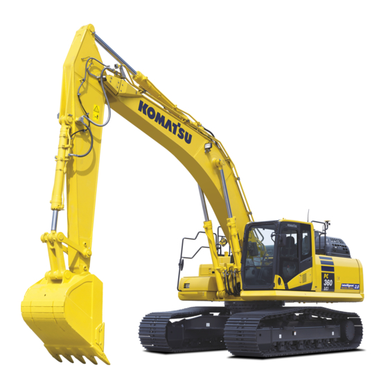
PC360LCi
PC390LCi
HYDRAULIC EXCAVATOR
SERIAL NUMBERS
ENGINE
This material is proprietary to Komatsu America Corp. and is not to be reproduced, used, or disclosed except in
accordance with written authorization from Komatsu America Corp.
It is our policy to improve our products whenever it is possible and practical to do so. We reserve the right to make
changes or improvements at any time without incurring any obligation to install such changes on products sold
previously.
Due to this continuous program of research and development, revisions may be made to this publication. It is
recommended that customers contact their distributor for information on the latest revision.
April 2019
PC360LCi-11 A38001
PC390LCi-11 A31001
6D114E-6
CEAM032703
-11
-11
and up
and up
Copyright 2019 Komatsu
Printed in U.S.A.
Komatsu America Corp.
Advertisement
Table of Contents

Related Manuals for Komatsu PC360LCi-11


Summary of Contents for Komatsu PC360LCi-11
- Page 1 6D114E-6 ENGINE This material is proprietary to Komatsu America Corp. and is not to be reproduced, used, or disclosed except in accordance with written authorization from Komatsu America Corp. It is our policy to improve our products whenever it is possible and practical to do so. We reserve the right to make changes or improvements at any time without incurring any obligation to install such changes on products sold previously.
- Page 2 READ AND UNDERSTAND THE OPERATION & MAINTENANCE MANUAL BEFORE OPERATING THIS VEHICLE OR PERFORMING ANY MAINTENANCE. Unsafe use of this machine may cause serious injury or death. Operators and maintenance personnel must read this manual, must be trained and authorized by the employer, before operating or maintaining this machine.
- Page 3 FOREWORD WARNING This Operation and Maintenance Manua l gives information re- lated to "intelligent Machine Control". Please read this Operation and Maintenance Manua l after read- ing the manual for the standard machine. CALIFORNIA CALIFORNIA Proposition 65 Warning Proposition 65 Warning Battery posts, terminals and Diesel engine exhaust and some of its related accessories contain lead...
- Page 4 It is provided on the back of the backrest of operator's seat. If this manual is lost or damaged, contact Komatsu or your Komatsu distributor and tell them about the machine model name and the serial No. immediately to arrange for its replacement.
- Page 5 FOREWORD SAFETY INFORMATION SAFETY INFORMATION To enable you to use the machine safely, and to prevent personal injury to operators, service personnel or by- standers, the precautions and warnings included in this manual and the safety signs attached to the machine must always be observed.
- Page 6 Utilizing the information provided in the operation to the other operations enables better productivity and quality in the whole operation. MAIN USE OF MACHINE This Komatsu machine is designed to be used mainly for the following work: • Digging work •...
- Page 7 MAINTENANCE PROCEDURE ........................ 4-3 EVERY 500 HOURS MAINTENANCE ....................4-3 SPECIFICATIONS ............................5-1 SPECIFICATIONS ............................ 5-2 SPECIFICATIONS: PC360LCI-11, PC390LCI-11 ................5-2 ATTACHMENTS AND OPTIONS ........................6-1 METHOD FOR CHANGING CONTROL PATTERNS ................6-2 CONTROL PATTERNS OTHER THAN STANDARD CONTROL METHOD ........6-3 RECOMMENDED ATTACHMENT OPERATIONS..................
- Page 8 TABLE OF CONTENTS FOREWORD INTELLIGENT MACHINE CONTROL SETTINGS..................7-2 CONTROL BOX............................7-3 METHOD FOR DISPLAYING MAIN MENU..................7-3 MACHINE MONITOR..........................7-180 MC SETTING..........................7-180 EXECUTIONS..............................8-1 SEMI-AUTO MODE ..........................8-2 PRECAUTIONS FOR OPERATION ....................8-2 PRECAUTIONS FOR REPLACING PARTS AND FAILURES ............8-4 WORKING MODE..........................
- Page 9 SAFETY This section describes cautions which are necessary to provide the efficient operation with “intelligent Machine Control”. Please follow the instructions described in the Operation and Maintenance Manual for the standard machine for safety information of the whole ma- chine.
- Page 10 SAFETY SAFETY SAFETY SAFETY LABELS ............................2-3 LOCATION OF SAFETY LABELS......................2-4 SAFETY LABELS ............................. 2-5 PRECAUTIONS FOR OPERATION ......................... 2-8 START ENGINE............................2-8 CHECKS AND ADJUSTMENT BEFORE STARTING ENGINE ............2-8 PRECAUTIONS RELATED TO CONTROL BOX..................2-8 PRECAUTIONS RELATED TO SEMI-AUTO MODE ................. 2-9 PRECAUTIONS FOR TRANSPORTATION....................
- Page 11 If the safety labels are damaged, lost, or cannot be read properly, replace them with new ones. For details of the part numbers for the safety labels, see this manual or the actual label, and place an order to your Komatsu distributor. •...
- Page 12 SAFETY LABELS SAFETY LOCATION OF SAFETY LABELS Options are shown with ★ marks in the figure.
- Page 13 SAFETY SAFETY LABELS 1. Caution for operation, inspection and maintenance 18. Caution for work equipment 2. Caution before operating 19. Caution for handling battery 3. Caution when leaving operator's seat 20. Prohibition of start by short-circuiting 4. Caution against high-voltage cables 21.
- Page 14 SAFETY LABELS SAFETY Warning! a. Caution when opening or closing front window b. Caution for moving control box Auto/manual switch “2A5-00-21220”...
- Page 15 SAFETY SAFETY LABELS Boom secondary drive switch “2A5-00-21350” Caution for cylinder function when starting engine “208-00-27130”...
- Page 16 PRECAUTIONS FOR OPERATION SAFETY PRECAUTIONS FOR OPERATION START ENGINE CHECKS AND ADJUSTMENT BEFORE STARTING ENGINE Perform the following checks before starting the engine at the beginning of the day's work to ensure that there is no problem with the operation of the machine. If these checks are not performed properly, problems may occur with the operation of the machine, and there is a danger that may lead to serious personal injury or death.
- Page 17 Relying only on the monitor screen of the control box for performing the work is dangerous. See with your own eyes when perform the work. Consult a Komatsu distributor when the intelligent Machine Control devices are used along with other systems. The system malfunction, such as communication error between devices may occur.
- Page 18 PRECAUTIONS FOR OPERATION SAFETY • Always use ramps of adequate strength. Be sure that the ramps are wide, long, and thick enough to provide a safe loading slope. Take suitable steps to prevent the ramps from moving out of position or coming off. (1) Chocks (2) Ramp (3) Center of ramp...
- Page 19 OPERATION This section describes cautions which are necessary to provide the efficient operation with “intelligent Machine Control”. Please follow the instructions described in the Operation and Maintenance Manual for the standard machine for operation information of the whole ma- chine.
- Page 20 GENERAL VIEW OPERATION GENERAL VIEW MACHINE EQUIPMENT NAME (1) Bucket (7) Engine hood (2) Bucket cylinder (8) Sprocket (3) Arm (9) Track frame (4) Arm cylinder (10) Track (5) Boom (11) Idler (6) Boom cylinder...
- Page 21 OPERATION GENERAL VIEW Details of A and B part (12) Komatsu Closed Crankcase Ventilation (hereafter (16) Battery KCCV) ventilator (17) Battery disconnect switch (13) Selective Catalytic Reduction (hereafter SCR) (18) System operating lamp (14) Komatsu Diesel Particulate Filter (hereafter (19) Fusible link...
- Page 22 GENERAL VIEW OPERATION Details of C to F part (21) Stroke sensor for bucket cylinder (25) GNSS antenna (22) Stroke and reset sensor for bucket cylinder (26) Stroke and reset sensor for boom cylinder (23) Stroke sensor for arm cylinder (27) Stroke sensor for boom cylinder (24) Stroke and reset sensor for arm cylinder...
- Page 23 OPERATION GENERAL VIEW CAB EQUIPMENT NAMES (1) Ceiling window (8) Power supply outlet (2) Front window (9) Fuse 1 (3) Emergency escape hammer (10) Fire extinguisher (if equipped) (4) Door lock release lever (11) Fuse 2 (5) Drink box (12) Control box (6) Cup holder (13) Network modem (7) Ashtray...
- Page 24 EXPLANATION OF COMPONENTS OPERATION EXPLANATION OF COMPONENTS The following is an explanation of devices necessary to operate the machine. To perform suitable operations correctly and safely, it is important to completely understand methods of operat- ing the equipment, and the meanings of the displays. EXPLANATION OF MACHINE MONITOR EQUIPMENT AA: Standard screen, EE: Warning or Error screen, DD: Guidance screen (1) Warning display...
- Page 25 OPERATION EXPLANATION OF COMPONENTS Displaying only meters On the standard screen (for camera display and meter display), you can shift the display to only the meter dis- play by pressing switch F3. For details, see the Operation and Maintenance Manual of standard machine. AA: Standard screen, EE: Warning or Error screen, DD: Guidance screen (1) Warning display (4) Monitor switch area...
- Page 26 EXPLANATION OF COMPONENTS OPERATION (1) Seat belt caution lamp (6) Engine coolant temperature caution lamp (2) Caution lamp (7) Hydraulic oil temperature caution lamp (3) Caution lamp (8) Fuel level caution lamp (4) Caution lamp (9) Caution lamp (5) Action level display Standard screen (camera display and meter display) When 1 type of caution is generated, it is displayed on the caution lamp (2).
- Page 27 OPERATION EXPLANATION OF COMPONENTS For details, see the Operation and Maintenance Manual of standard machine. (1) Seat belt caution lamp (5) Engine coolant temperature caution lamp (2) Caution lamp (6) Hydraulic oil temperature caution lamp (3) Caution lamp (7) Fuel level caution lamp (4) Action level display (8) Caution lamp Standard screen (only meters are displayed)
- Page 28 Stop the operation, and run the engine at medium speed with │ mittently no load or stop it. │ If the condition is not improved, ask your Komatsu distributor │ for inspection and maintenance. ↓ Does not Lights up in...
- Page 29 OPERATION EXPLANATION OF COMPONENTS Caution lamps and display colors Display color/ Machine condition (action level) Symbol Type of caution lamp Yellow White Blue Equipment state caution lamp Abnormal Abnormal for the intelligent Machine Con- (L03, L04) (L01) trol Abnormal Abnormal System state caution lamp for the intelligent Machine Control (L03, L04)
- Page 30 Stop the machine immediately, and have the inspection and maintenance performed. Ask your Komatsu distributor for an inspection and mainte- nance. When action level “L03” is displayed The caution lamp lights up in red and the alarm buzzer sounds intermittently.
- Page 31 The intelligent Machine Control cannot be performed but other work than the intelligent Machine Control can be performed, since the intelligent Machine Control function is limited. If this caution lamp does not go out, ask your Komatsu distributor for inspection and maintenance. Intelligent Machine Control SYSTEM STATE CAUTION LAMP...
- Page 32 EXPLANATION OF COMPONENTS OPERATION If this caution lamp does not go out although starting switch is operated, ask your Komatsu distributor for in- spection and maintenance. CYLINDER FUNCTION STATE CAUTION LAMP Cylinder function state caution lamp displays the state that stroke measuring function of cylinder has not been reset.
- Page 33 OPERATION EXPLANATION OF COMPONENTS SWITCH 9JD29720 (1) One-touch power maximizing switch (10) Cigarette lighter (2) Horn switch (11) Room lamp switch (3) Starting switch (12) Seat heater switch (if equipped) (4) Fuel control dial (13) Engine shutdown secondary switch (5) Lamp switch (14) Pump secondary drive switch (6) Swing lock switch (15) Swing parking brake cancel switch...
- Page 34 EXPLANATION OF COMPONENTS OPERATION (19) Breaker operation switch (22) Offset down switch (20) Offset up switch (23) Auto/manual switch (21) Not used (24) Not used LAMP SWITCH Lamp switch is used to make the working lamp and monitor illu- mination light up. (a) Night position Lamps light up and monitor illumination and control box are set to night mode.
- Page 35 OPERATION EXPLANATION OF COMPONENTS AUTO/MANUAL SWITCH You can switch between semi-auto mode and manual mode by using Auto/Manual switch. For the switching method, see “SEMI-AUTO MODE SETTINGS (8-5)”. For semi-auto mode, see “SEMI-AUTO MODE (8-2)”. (a) Semi-auto mode Pressing this switch during manual mode changes the mode to semi-auto mode.
- Page 36 EXPLANATION OF COMPONENTS OPERATION (b) Manual mode Pressing this switch during the semi-auto mode changes the mode to the manual mode. The symbol indicating the manual mode is displayed on the control box, and voice signal sounds. Shifting from the semi-auto mode to the manual mode can be performed regardless of the machine condition.
- Page 37 To cancel the lock, return the lock lever to LOCK position (L), check that each control lever and the attachment switch are in neutral, and then release the lock lever again. For the genuine hydraulic oils which Komatsu recommends, see the Operation and Maintenance Manual of standard ma- chine.
- Page 38 EXPLANATION OF COMPONENTS OPERATION intelligent Machine Control SYSTEM CONTROL BOX WARNING • Do not operate the control box during the operation of the work equipment in order to prevent unex- pected accident from occurring. Also, do not gaze the control box during performing the work. •...
- Page 39 OPERATION EXPLANATION OF COMPONENTS Power supply state LED • Power supply state LED displays the state of control box power supply. • Control box power is supplied from GNSS receiver. Display of the internal battery Display of the external power sup- State state LED (2) ply state LED (3)
- Page 40 • The intelligent Machine Control system can be stopped individually regardless of ON/OFF of starting switch. For this setting, consult your Komatsu distributor. • When the individual end is set, take care not to forget ending the intelligent Machine Control system.
- Page 41 Use an antenna for network modem which KOMATSU recommends always when using this device. If an antenna which is not recommended by KOMATSU is used, it may not be complied with the regula- tions in the country or area where the machine is used. This is because the network modem is a wire- less device which uses radio wave.
- Page 42 (2) Communication state LED (5) Connector port 1 (3) Blue tooth state LED (6) Connector port 2 How these various state LED work For questions about the communication, consult your Komatsu distributor. Display of the power supply state LED (1) Lighting color State...
- Page 43 OPERATION EXPLANATION OF COMPONENTS Lighting color State Not being connected to SiteLink server. Flashing in green (No GPRS connection information is obtained) Connection to SiteLink server is established, but no RTK compensation informa- Green tion is obtained. Green, red Connection to SiteLink server is established, and GPS compensation information is received.
- Page 44 EXPLANATION OF COMPONENTS OPERATION Check that the wiper blade is stowed in the right stay. Turn the handle (2) of mount to loosen it. Face the screen of control box toward left of the machine, and tilt it so that the bottom (G) of control box is parallel to the screen (H) of machine monitor.
- Page 45 OPERATION EXPLANATION OF COMPONENTS Hold the handles (A) (2 places) on the right and left top sides of the front window, and pull the levers (B) (2 places) to release the locks at the top of the front window. The top of the front window will come out. 3-27...
- Page 46 EXPLANATION OF COMPONENTS OPERATION Hold the lower handle (C) with your left hand from inside the operator's cab, and with your right hand, grip the top handle (D), pull it up, and push it securely against the lock catch (E) at the rear of the cab to lock the window. Pull up the front window checking that the front window does not interfere with the control box.
- Page 47 OPERATION EXPLANATION OF COMPONENTS Check that the lever (B) is securely at LOCK position. • The lock is engaged if the arrow on lock case (F) matches the position of the arrow on lever (B). Check visually. • The lock is not engaged if the arrow on the lock case (F) does not match the position of the arrow on the lever (B).
- Page 48 EXPLANATION OF COMPONENTS OPERATION Face the screen of control box toward left of the machine, and tilt it so that the bottom of control box is parallel to the screen of machine monitor. Turn the handle of mount to tighten it in order to fix the control box.
- Page 49 OPERATION EXPLANATION OF COMPONENTS Grip the handle (C) at the bottom of the front window with your left hand and the handle (D) at the top with your right hand, push the cab front window to the front, then lower it slowly.
- Page 50 EXPLANATION OF COMPONENTS OPERATION 10. Adjust the control box to the position for you to see it well. 11. Turn the handle (2) of mount to screw it in, and fix the con- trol box so that it does not move. 12.
- Page 51 OPERATION EXPLANATION OF COMPONENTS CUP HOLDER The cup holder is located on the left side of the operator's seat. POWER SUPPLY OUTLET 24V power supply NOTICE Do not use this as a power supply for 12 V equipment. This will cause a failure of the equipment. When cigarette lighter is removed, the lighter socket can be used as a power source.
- Page 52 EXPLANATION OF COMPONENTS OPERATION Fuse 1 Fuse capacities and circuit names Fuse ca- Name of circuit pacity 5 A Relay for lamp, emergency switch 30 A Solenoid valve 5 A PPC hydraulic lock solenoid 10 A Window washer, cigarette lighter 10 A Horn 5 A Auto preheater relay 10 A Not applicable 10 A...
- Page 53 OPERATION EXPLANATION OF COMPONENTS Fuse 2 Fuse ca- Name of circuit pacity ICT sensor controller, work equipment con- 5 A troller, voice amplifier 20 A GNSS receiver, control box 10 A Spare 10 A Spare 10 A Spare 5 A 5 A Solenoid valve 20 A Solenoid valve 20 A Boom secondary drive switch (10)
- Page 54 EXPLANATION OF COMPONENTS OPERATION METHOD FOR REMOVING AND INSTALLING CONTROL BOX WARNING • For the removal and installation of control box, place the machine on a level ground, lower the work equipment to the ground, stop the engine, check the power supply of control box is off, and then perform the operation.
- Page 55 OPERATION EXPLANATION OF COMPONENTS Turn the ring (4) of the wiring harness connector (2) coun- terclockwise to disconnect the connector. Put the cap on the disconnected connector to prevent the dust from entering. Control box side connector: Red cap Chassis harness side connector: Yellow cap REMARK 3 each of caps including spares are attached to the ma- chine.
- Page 56 EXPLANATION OF COMPONENTS OPERATION METHOD FOR INSTALLING CONTROL BOX Lower the work equipment to the level ground, and set the lock lever (1) securely to LOCK position (L). Stop the engine. Hold the cab fixing ball (C) and ball (D) at the rear of con- trol box with the mount (B), and turn the handle (A) of the mount (B) clockwise to fix the mount.
- Page 57 OPERATION EXPLANATION OF COMPONENTS REMARK When connecting the connector, support the ring as shown in the right figure so that it can be turned easily. Move the wiring harness connector (2) to make the angle (X) of approximately 15 ° by seeing the wiring harness connector (2) from directly above, and hold it.
- Page 58 Check around DEF tank for dirt, and clean the blue DEF filler cap and the area around. Check DEF tank, pump, injector, and hoses and their connections for leakage. If any problem is found, ask your Komatsu distributor for repair.
- Page 59 11. Check the seat belt and mounting hardware. Check the seat belt and mounting hardware for any abnormality. If any damage is found, ask your Komatsu distributor to replace it with new one.
- Page 60 MACHINE OPERATIONS AND CONTROLS OPERATION METHOD FOR ADJUSTING METHOD FOR ADJUSTING OPERATOR'S SEAT WARNING • Set the lock lever to LOCK position (L) and stop the engine always when adjusting the position of the oper- ator's seat in order to prevent any malfunction due to accidental contact with the control levers.
- Page 61 OPERATION MACHINE OPERATIONS AND CONTROLS • To raise the front of the seat, apply your weight to the rear of the seat, while pulling up lever. • To lower the front of the seat, apply your weight to the front of the seat, while pulling up lever.
- Page 62 MACHINE OPERATIONS AND CONTROLS OPERATION Adjust the height of armrest (3) while pulling plunger (2). Push back plunger (2) after aligning it to the height adjust- ment hole of armrest (3). Tighten knob (1) at the rear of the armrest. NOTICE If you loosen knob (1) at the rear of the armrest too much, it touches the stopper in cover (4) and you can-...
- Page 63 OPERATION MACHINE OPERATIONS AND CONTROLS Turn the seat heater switch ON. (a): OFF position (b): ON position The seat cushion and backrest become warm. METHOD FOR REMOVING AND INSTALLING HEADREST METHOD FOR REMOVING HEADREST When the headrest is not necessary, remove it according to the following procedure. Pull up the headrest 80 mm {3.1 in} ...
- Page 64 MACHINE OPERATIONS AND CONTROLS OPERATION METHOD FOR ADJUSTING CONTROL BOX POSITION WARNING • In order to perform the position adjustment of control box, place the machine on a level ground, lower the work equipment to the ground, stop the engine, and check that the power supply of con- trol box is off.
- Page 65 OPERATION MACHINE OPERATIONS AND CONTROLS REMARK If adjustment is not enough with this position adjustment of control box, slide the whole seat, and perform the position adjustment of R.H. work equipment control lever. For the adjustment method, see “METHOD FOR ADJUSTING OP- ERATOR'S SEAT”.
- Page 66 MACHINE OPERATIONS AND CONTROLS OPERATION NOTICE • Check that the fuel control dial (2) is at Low idle (MIN) position before starting the engine. The engine will ac- celerate suddenly and cause damage to the engine parts if the fuel control dial is at High idle (MAX) posi- tion.
- Page 67 OPERATION MACHINE OPERATIONS AND CONTROLS Turn starting switch key (3) to ON position (B). The preheating monitor lights up and automatic preheating is performed if the ambient temperature is low. Keep the starting switch key (3) at ON position (B) until the preheat- ing monitor goes out.
- Page 68 MACHINE OPERATIONS AND CONTROLS OPERATION After the engine starts, wait for the engine oil pressure caution lamp to go out. Do not touch the control levers or control pedal while the engine oil pressure caution lamp is lit. NOTICE If the engine oil pressure caution lamp does not go out in 4 to 5 seconds, stop the engine immediately.
- Page 69 OPERATION MACHINE OPERATIONS AND CONTROLS Control box starts automatically. NOTICE Do not turn the starting switch to OFF position before starting of control box is completed. This may cause failures of the control box. Before turning the starting switch to OFF position, make sure that the starting of control box is completed.
- Page 70 MACHINE OPERATIONS AND CONTROLS OPERATION Method for resetting stroke of the work equipment cylinder CAUTION Reset the stroke of work equipment cylinder always after the engine is started, and move the machine. The cylinder sensor may mistakenly detect the stroke and causes the work equipment to move unex- pectedly if the operation is started without resetting the work equipment cylinder.
- Page 71 OPERATION MACHINE OPERATIONS AND CONTROLS Turn the starting switch of machine to OFF position (A). The power supply of machine is turned off, and the power sup- ply of control box is also turned off automatically. When not turning off the power supply of the machine (engine) and turn off the power supply of control box Display the main menu screen of the control box.
- Page 72 OFF position associated with long-term storage or maintenance. Performing wrong procedure may break the intelligent Machine Control system, and the system may not start normally. If it does not start normally, consult your Komatsu distributor. METHOD FOR STOPPING ENGINE WARNING Keep away from the exhaust pipe immediately after stopping the engine.
- Page 73 OPERATION MACHINE OPERATIONS AND CONTROLS NOTICE Do not stop the engine abruptly except in an emergency. Otherwise, the service lives of component parts of the en- gine will be reduced. If the engine is overheated, do not try to stop it abruptly but run it at medium speed to allow it to cool down gradu- ally, and then stop it.
- Page 74 MACHINE OPERATIONS AND CONTROLS OPERATION REMARK • Turn the starting switch key (1) to OFF (A) position, and the control box also shuts down at the same time. • When the key in starting switch (1) is turned to OFF (A) position, the engine stops, but the machine's main power supply is not turned off immediately.
- Page 75 OPERATION MACHINE OPERATIONS AND CONTROLS METHOD FOR PARKING MACHINE WARNING • Stop the machine gradually. Avoid a sudden stop. • Place the machine on a firm and level place. Do not park the machine on a slope. Block the tracks from movement if it is unavoidably necessary to park the machine on a slope.
- Page 76 MACHINE OPERATIONS AND CONTROLS OPERATION Lower the bucket to the ground with its bottom face hori- zontal. Set the lock lever (3) to LOCK position (L). Check the engine coolant temperature and the engine oil pressure with the machine monitor. •...
- Page 77 OPERATION HANDLING RADIO HANDLING RADIO • To ensure safety, always keep the volume to a level where you can hear the outside sounds during opera- tion. • If water gets into the speaker case or radio, it may lead to failure. Take care not to let water get on them. •...
- Page 78 TRANSPORTATION OPERATION TRANSPORTATION For the method of transportation, see the Operation and Maintenance Manual of standard machine, OPERA- TION, “TRANSPORTATION”. However, this machine is different from standard machine in machine weight, radio antenna, GNSS antenna bracket, and work equipment cylinder with sensor which automatically controls work equipment. For the transportation, see the Operation and Maintenance Manual of standard machine.
- Page 79 OPERATION TRANSPORTATION Install the dustproof cap (9) to the connector for GNSS an- tenna. Check that there is no dust or water drop inside the dust- proof cap (10). Install the dustproof cap (10) to the connector (5) for GNSS antenna cable, and fix it to the bracket (1). METHOD FOR INSTALLING GNSS ANTENNA Remove the GNSS antenna and the dust proof caps (9) and (10) of GNSS antenna cable.
- Page 80 If the cap is not put on, the dust easily enters the inside. REMOVE AND INSTALL HANDRAIL Consult your Komatsu distributor for handling of the handrails when the machine is transported. This is because the total height may exceed the height regulation depending on the height of the trailer.
- Page 81 OPERATION TRANSPORTATION WARNING • After the machine is transported, be sure to install the handrails before inspection and mainte- nance. • Use the crane etc. for carrying the handrails. There is a danger of rolling over or falling from high place that can lead to serious personal injury or death.
- Page 82 Perform a daily calibration after installing the hand rail. For details, see “DAILY CALIBRATION (8-30)”. If the bucket edge accuracy is degraded, consult your Komatsu distributor and perform the antenna calibration. REMOVE AND INSTALL GNSS ANTENNA AND ANTENNA FOR NETWORK...
- Page 83 OPERATION TRANSPORTATION Remove the cover, and take the antenna cable (11) out through the slit (13) of the grommet (12). 3-65...
- Page 84 TRANSPORTATION OPERATION Remove the GNSS antenna. Remove the GNSS antenna (1) from the antenna cable connector. • When built-in specification is used for GNSS radio device Remove the GNSS antenna (1) from the antenna cable connector (5) (CN-AA39). • When external specification is used for GNSS ra- dio device Remove the GNSS antenna (1) from the antenna cable connector (9) (CN-AA26).
- Page 85 OPERATION TRANSPORTATION Remove the antenna for network modem. Remove the antenna (2) for network modem from the antenna cable connector (14) (CN-AA37). Tilt the antenna (2) for network modem, and pull it up straight to remove. NOTICE • Do not slide the antenna (2) for network mo- dem sideways when it is removed from the cab.
- Page 86 GNSS antenna is connected. Consult your Komatsu distributor when the machine is transported. Install the GNSS antenna (1) and the antenna (2) for network modem according to the following procedure.
- Page 87 OPERATION TRANSPORTATION • When external specification is used for GNSS ra- dio device Remove the waterproof cap (10) installed to the antenna cable connector (9) (CN-AA26), and in- stall it to the cap holder (8). Install the GNSS antenna (1) to the antenna cable connector. •...
- Page 88 TRANSPORTATION OPERATION Installing the cover (3) Tighten the mounting bolt (4) at the rear of cab, and fix the cover (3). Insert the antenna cable (11) into inside through the slit (13) of the grommet (12). Set these antennas (1) and (2) as far from radio an- tenna as possible.
- Page 89 Perform engine warm-up operation when starting the engine after long-term storage by referring to the Opera- tion and Maintenance Manual of standard machine. Perform daily calibration when performing the intelligent Machine Control. Ask your Komatsu distributor for repair if the accuracy of bucket edge is deteriorated. 3-71...
- Page 90 TROUBLES AND ACTIONS OPERATION TROUBLES AND ACTIONS IF ERROR INFORMATION IS DISPLAYED ON CONTROL BOX The following warning message (in red or yellow) is displayed on the screen if any abnormality occurs during operation or starting the engine. Place the machine as follows if an error message is displayed. •...
- Page 91 OPERATION TROUBLES AND ACTIONS The warning messages of "Initializing..." (satellite communication is in poor condition) are the following warning messages displayed on the control box. • “Waiting for satellites...” • “Waiting for radio link...” • “Waiting to initialize...” • “Initializing...” NOTICE The purpose of this function is to reduce the case that the function of semi-auto mode is limited while the satellite communication is degraded.
- Page 92 • Contact your Komatsu distributor for the remedies indicated with (*) in the remedy column. • Ask your Komatsu distributor for repairs for problems or causes which are not listed below. ERROR BY FAILURE IN THE ELECTRICAL COMPONENT Back- Semi-...
- Page 93 If there is no abnormality in the cables, ICT sensor controller or control box has a trouble. Check if the failure code is not displayed on machine monitor, and then ask your Komatsu distributor for an in- vestigation of the cause and repair of it.
- Page 94 If the setting is correct, tilt sensor or wiring harness has a trouble. Check if the failure code is not displayed on machine monitor, and then ask your Komatsu distributor for an investigation of the cause and repair of it.
- Page 95 The machine entered the operation Avoidance Area Breach! Yellow the operation prohibited prohibited area. area. Komatsu controller is Calibration on machine monitor is in Finish the calibration on busyCalibration Rejected! process. machine monitor. *1: The state varies depending on the setting of semi-auto hold time which was initialized.
- Page 96 TROUBLES AND ACTIONS OPERATION ACTION FOR Waiting for satellites Phenomena: The system is acquiring satellites. Wait for a while. Check if there is an obstacle around GNSS antenna (tall building, tree, wall, etc. which disturbs communication or reflects radio wave). If there is an obstacle, move to the place with no obstacle, and wait for a while.
- Page 97 If the cables have no trouble, modem of GNSS radio device or GNSS receiver may have a trouble. Check if the failure code is not displayed on machine monitor, and then ask your Komatsu distributor for an investigation of the cause and repair of it.
- Page 98 TROUBLES AND ACTIONS OPERATION When the connector is connected correctly On the “GNSS Status” menu, select “Fix” tab. Check that “Initialized!” is displayed on “Main GPS” and “Aux GPS”. If “Initialized!” is not displayed, tap the “Reset receiver” button of the antenna which has not yet been “Initialized!” by using “Info”...
- Page 99 OPERATION TROUBLES AND ACTIONS When the connector is connected correctly On the “GNSS Status” menu, select “Fix” tab. Check that “Initialized!” is displayed on “Main GPS” and “Aux GPS”. If “Initialized!” is not displayed, tap the “Reset receiver” button of the antenna which has not yet been “Initial- ized!”by using “Info”...
- Page 100 TROUBLES AND ACTIONS OPERATION ACTION FOR Low precisions Phenomena: Bucket edge accuracy is low. If the locus condition (position, number, etc.) of GNSS satellite is bad, the blade edge accuracy is degraded to a “Low preci- sions...” state. This is not a system error. Wait for the locus condition to be re- stored.
- Page 101 OPERATION TROUBLES AND ACTIONS ACTION FOR Komatsu controller is busy Calibration Rejected Phenomena: Calibration on machine monitor is in process, wait for a while until it is completed. DISPLAY OF MESSAGES OF Sitelink3D The following messages are not abnormalities but take a remedy according to the message.
- Page 102 TROUBLES AND ACTIONS OPERATION ACTION FOR You are in *** delay status Phenomena: Delay status is set on the site link menu. You do not need to stop the operation, but the delay status in- formation is displayed at the office side if it is set. The following is the procedure for canceling the setting of delay status.
- Page 103 MAINTENANCE Please read and make sure that you understand the SAFETY section before reading this section.
- Page 104 MAINTENANCE SCHEDULE MAINTENANCE MAINTENANCE SCHEDULE If the currently used diesel fuel which does not include the bio-fuel is changed to the one mixed with the bio-fuel, the replacement interval of the fuel filter is changed as well. See “MAINTENANCE INTERVAL WHEN DIESEL FUEL MIXED WITH BIO-FUEL IS USED”.
- Page 105 MAINTENANCE MAINTENANCE PROCEDURE MAINTENANCE PROCEDURE EVERY 500 HOURS MAINTENANCE Maintenance for every 50 and 250 hours should be performed at the same time. METHOD OF CHECKING LOOSENESS OF BUCKET CYLINDER STROKE SEN- SOR WIRING HARNESS CLAMP, HARDENING OF RUBBER Check visually and by touching with hand that there is no loose clamp mounting bolts and no hardening of the rubber for the bucket cylinder stroke sensor wiring harness.
- Page 107 SPECIFICATIONS...
- Page 108 SPECIFICATIONS SPECIFICATIONS SPECIFICATIONS SPECIFICATIONS: PC360LCI-11, PC390LCI-11 Item Unit PC360LCI-11 PC390LCI-11 Operating weight kg {lb} 36200 {79807} 39217 {86459} Bucket capacity m {cu/yd} 1.4 {1.8} Engine model Komatsu SAA6D114E-6 diesel engine SAE J1995 202 {271} / 1950 {1950} (gross) kW {HP}/...
- Page 109 SPECIFICATIONS SPECIFICATIONS Working ranges (mm) PC360LCI-11 PC390LCI-11 Max. digging reach 11100 {36' 5"} Max. digging depth 7380 {24' 2"} 7278 {23' 11"} Max. digging height 10210 {33' 6"} 10312 {33' 10"} Max. vertical wall digging depth 6480 {21' 3"} 6378 {20' 11"} Max.
- Page 111 ATTACHMENTS AND OPTIONS Please read and make sure that you understand the SAFETY section before reading this section.
- Page 112 METHOD FOR CHANGING CONTROL PATTERNS ATTACHMENTS AND OPTIONS METHOD FOR CHANGING CONTROL PATTERNS WARNING • When operating the machine, check that the display of the control pattern card is matched to the operation of the machine to prevent personal injury by malfunction. If it does not match, replace it immediately with the correct control pattern card.
- Page 113 ATTACHMENTS AND OPTIONS METHOD FOR CHANGING CONTROL PATTERNS Start the engine and set the lock lever in FREE position (F). Operate the work equipment control levers slowly to check that the pattern has been changed. CONTROL PATTERNS OTHER THAN STANDARD CONTROL METHOD WARNING •...
- Page 114 Select the optimum attachment model for the hydraulic excavator body. The attachments and models ready for installation differ according to the machine body. For details of the selection of the attachments or the models, consult your Komatsu distributor. HYDRAULIC BREAKER...
- Page 115 ATTACHMENTS AND OPTIONS RECOMMENDED ATTACHMENT OPERATIONS When the chisel does not penetrate or break the surface by continuous impact to the same impact surface for 1 minute, change the point of impact and perform breaking operations by scraping from the edge. The direction of penetration of the chisel and the direction of the breaker body will gradually move out of line with each oth- er, always adjust the bucket cylinder to keep them aligned.
- Page 117 SETTING...
- Page 118 INTELLIGENT MACHINE CONTROL SETTINGS SETTING INTELLIGENT MACHINE CONTROL SETTINGS Settings of the intelligent Machine Control can be performed with the control box and machine monitor. Control box • “MAIN MENU DISPLAY (7-3)” • “PROJECT FILE SETTING AND EDITING (7-4)” • “GUIDANCE SETTINGS (7-53)”...
- Page 119 SETTING CONTROL BOX CONTROL BOX METHOD FOR DISPLAYING MAIN MENU On the main menu screen of control box, settings of intelligent Machine Control system can be performed. Tap the main menu display button at the bottom right of the working screen, the screen changes to “Menu” screen. REMARK •...
- Page 120 CONTROL BOX SETTING Tools button Tap “Tools” button, and you can perform other settings of the intelligent Machine Control. Machine Setup button Tap “Machine Setup” button, and you can perform various settings of the machine for the intelligent Machine Control. Exit button Tap the Exit button, and you can finish the control box.
- Page 121 SETTING CONTROL BOX PROJECT FILE SETTING CONTENTS You can perform the setting and editing of the following items with the Project File Settings. (1) “Project Files” button. You can perform the setting and editing of the Project File. (2) “Current Project:” The currently selected Project File is displayed.
- Page 122 CONTROL BOX SETTING Highlight the Project File to be imported, and tap ENTER button. The Project File is set. REMARK Even if the currently selected Project File is highlighted, it cannot be selected by ENTER button. After setting is completed, the name of currently selected Project File is displayed in “Current Project:”...
- Page 123 SETTING CONTROL BOX The screen changes to the screen for inputting Project File name. Input the file name to be created newly, and tap “OK” button. The file name of the newly created Project File is added to the Project Files list. Tap RETURN button to return the screen to the previous screen.
- Page 124 CONTROL BOX SETTING The screen changes to the screen for inputting Project File name. Input the file name to be created newly, and tap OK button. The file name of the newly created Project File is added to the Project Files list. Tap RETURN button to return the screen to the previous screen.
- Page 125 SETTING CONTROL BOX The screen changes to the screen for inputting Project File name. Input the file name to be created newly, and tap “OK” button. The file name of the newly created Project File is added to “Project Files” list. Tap RETURN button to return the screen to the previous screen.
- Page 126 CONTROL BOX SETTING With “From:”, select the folder (3DMC folder) in which the file will be saved (in the control box) from the drive having the original file (to which USB flash drive is connected). Example: F: to 3DMC folder Highlight the Project File to be copied, and tap “Copy”...
- Page 127 SETTING CONTROL BOX When copying the Project File saved in the control box to the USB flash drive With “From:”, select the drive to which the file will be cop- ied (to which the USB flash drive is connected) from the folder (in the control box) in which the Project File is saved.
- Page 128 CONTROL BOX SETTING METHOD FOR EXPORTING PROJECT FILE The Project Files consist of Control files, Point files, Surface files, Layer files, etc. On “Project Files” setting screen, select the Project File which contains the file to be exported, and tap the Export button.
- Page 129 SETTING CONTROL BOX With “Where:”, select the place to where the file is export- ed (the drive to which the USB flash drive is connected). REMARK If you set 3DMC folder (place where File is saved in con- trol box) as the folder to where File is exported, the data is overwritten.
- Page 130 CONTROL BOX SETTING CONTROL POINT SETTING CONTENTS Function of “Control Points” setting is as follows. Contents displayed in “Control Points” setting (1) “Name”: Name of Control Point (2) “H.Error”: Error in horizontal direction (3) “V.Error”: Error in vertical direction Contents controlled by “Control Points” setting (4) “Add”: Adds Control Point.
- Page 131 SETTING CONTROL BOX To use it, put a tick in the check box. By putting a tick, this Control Point becomes the vertical Control Point. (6) “Measure...”: You can obtain the Control Point Coordinates. This is used to obtain the localized GNSS Coordinates. Tap “Measure...”...
- Page 132 CONTROL BOX SETTING Highlight the Control Point to be edited on “Control Points” set- ting screen, tap “Edit” button, and the screen changes to “Con- trol points” editing screen. You can input the Point obtained by measurement and Coordi- nates data of the existing Point. On “Control points”...
- Page 133 SETTING CONTROL BOX To delete them, tap ENTER button. The Control Point will be deleted. Not to delete it, tap RETURN button. Control Point is not deleted and the screen returns to the previous screen. IMPORT CONTROL POINTS The Control Points saved in the USB flash drive can be imported into the control box. Tap “Import”...
- Page 134 CONTROL BOX SETTING METHOD FOR COPYING CONTROL POINT FILES FROM USB FLASH DRIVE With “What:”, select “3D Control Point file (GC3)”. With “Where:”, select F: (the drive to which USB flash drive is connected). Highlight the Control files to be imported, and tap ENTER button to import.
- Page 135 SETTING CONTROL BOX To import the Control files, put a tick in the check box. After putting a tick in it, a message of “Caution:This will overwrite the existing localization!” is displayed. When it is OK to be overwritten, tap “Next>” button. REMARK Even if you tap “Next>”...
- Page 136 CONTROL BOX SETTING SELECT WORLD GEODETIC SYSTEM (WGS) COORDINATES You can select “World Geodetic System”. Tap “Coord. System” button on “Control points” setting screen. METHOD FOR USING LOCALIZATION You can select “World Geodetic System”. Select “Coord. system” tab, and select “Use localization”. The Control Point which is measured based on USA WGS84 “World Geodetic System 1984”...
- Page 137 SETTING CONTROL BOX Select “Coord. system” tab, and select “Use predefined projec- tion”, and then use the coordinates system of “World Geodetic System”. Display contents of “Projection” tab (1) “Projection:”: The name of the Projection is displayed. (2) “Datum:”: The name of the world geodetic system is dis- played.
- Page 138 CONTROL BOX SETTING With “From:”, select the folder (3DMC folder) in which the file will be saved (in the control box) from the drive having the original file (to which USB flash drive is connected). Example: “F: to 3DMC folder” Highlight the Geoid File to be copied, and tap “Copy”...
- Page 139 SETTING CONTROL BOX When the Geoid File name is already in the list and copy- ing the file by overwriting, “MessageBox” is displayed. Tap ENTER button. REMARK • Display of the drive name depends on the connecting condition of USB flash drive. •...
- Page 140 CONTROL BOX SETTING POINT SETTING AND EDITING Control Point, Topo survey point, Surface point, etc. are prepared as Points, and you can perform the setting and editing with “Points” menu. Tap “Points” button on “Project File Settings” screen, the screen changes to “Points” setting screen. POINT SETTING CONTENTS Setting and editing function of “Control Points”...
- Page 141 SETTING CONTROL BOX Tap “New” button on the setting and editing screen of “Points”. The screen changes to “PointEditDialog” screen. The displayed contents of “PointEditDialog” screen (1) “Name”: The name of Point is displayed. (2) “Description”: The Remarks are displayed. (3) “Layer”: The name of Layer in which Point is saved is dis- played.
- Page 142 CONTROL BOX SETTING The displayed contents of “Points” screen (1) “Name”: The name of Point is displayed. (2) “Description”: The Remarks are displayed. (3) “Layer”: The name of Layer in which Point is saved is dis- played. (4) “North”: The value of N is displayed. (5) “East”: The value of E is displayed.
- Page 143 SETTING CONTROL BOX When the Surfaces are already saved in the Project File, the list of the Surface names is displayed in “Surface” column. When the Surface is not saved in the Project File, no name is displayed in the column. Create the Surface newly or import the Surface.
- Page 144 CONTROL BOX SETTING Even if you return to the working screen, Alignment is not displayed. METHOD FOR EDITING SURFACES You can edit the Surface. Tap “Surfaces” button on the Project File setting screen. The screen changes to “Surfaces” editing screen. The contents displayed on “Surfaces”...
- Page 145 SETTING CONTROL BOX • “Crown road surface” You can create the Surface for Alignment. • “Triangulated surface from topo survey” You can create the Surface based on the Topo survey point. • “Raise/Lower Existing Surface” You can create the Surface by offsetting the existing Surface vertically. •...
- Page 146 CONTROL BOX SETTING • When using bucket edge coordinates Set the bucket edge to arbitrary position, and tap “Measure Point” button. Measurement of the bucket edge coordi- nates starts. When the measurement is finished, the value is displayed in “Point on surface”. •...
- Page 147 SETTING CONTROL BOX Tap the item of “Grid interval” to input the Grid interval. Tap “<Back” button to return the screen to the previous screen. Tap “Cancel” button, and the screen returns to the editing screen of Surface. Tap “Exit” button, and the screen changes to the message box screen.
- Page 148 CONTROL BOX SETTING SLOPING PLANE SURFACE Highlight the Sloping Plane Surface in the Surface type, and tap “Next>” button. You can create the Sloping Plane Surface. (1) Main-fall SLOPING PLANE SURFACE SETTING CONTENTS (1) Coordinates of the Point of surface For the input procedure of Point, see “METHOD FOR EDITING SURFACES”.
- Page 149 SETTING CONTROL BOX Lower the bucket edge to the ground at an arbitrary place, tap “Measure Point” button or tap “Select” button to select any point, and display the Point Coordinates. Tap the item of “Grade” of “Main-fall (A->B)”, and input the numeric value.
- Page 150 CONTROL BOX SETTING The screen changes to the editing screen of Surface. Tap ENTER button. The creation of Surface is completed. Tap RETURN button on the editing screen of Surface, and the creation of Surface is canceled. 7-34...
- Page 151 SETTING CONTROL BOX Measure 2 arbitrary points on the existing slope, and create the Sloping Plane Surface. Measure the Coordinates of 2 points on the existing slope. Lower the bucket edge on “A” position, and tap “Measure Point” button. (1) Main-fall The coordinates of “A”...
- Page 152 CONTROL BOX SETTING 13. Tap “Exit” button, and the screen changes to “Message- Box” screen. 14. To reflect the created Surface to currently setting Surface, tap ENTER button. REMARK On this screen, even if you tap ENTER button, the setting will not be completed.
- Page 153 SETTING CONTROL BOX CROWN ROAD SURFACE SETTING CONTENTS (1) Setting of “Starting point” For the input procedure of Point, see “FLAT PLANE SUR- FACE”. (2) Input of machine grade in longitudinal direction “Direction”: Sets the direction to which Surface is displayed. Tap the item and you can input the numeric value.
- Page 154 CONTROL BOX SETTING 10. The screen changes to the editing screen of Surface. Tap ENTER button. The creation of Surface is com- pleted. 11. Tap RETURN button on the editing screen of Surface, and the creation of Surface is canceled. METHOD FOR CREATING SURFACE BY TRIANGULATED SURFACE FROM TOPO SURVEY Highlight “Triangulated surface from topo survey”...
- Page 155 SETTING CONTROL BOX METHOD FOR CREATING SURFACE BY OFFSETTING EXISTING SURFACE Highlight “Raise/Lower Existing Surface” in the Surface type, and tap “Next>” button. You can create the Surface by offsetting the existing Surface vertically. Highlight the Surface to be offset from “Name” list and tap Tap the item of “Elevation adjustment:”, and input the offset value.
- Page 156 CONTROL BOX SETTING Creation of Surface of the road (1) You can select the existing Alignment from the list. (2) You can offset the vertical Elevation of the road center line. Tap the item and you can input the offset value. (3) For the numeral value of “Left side:”...
- Page 157 SETTING CONTROL BOX Tap “Show” button. Each time it is tapped, “Yes/No” in the Show column switches. “Yes”: The Surface is displayed. “No”: The Surface is not displayed. REMARK You cannot set the Display/Non-display for the file which is set as Surface.
- Page 158 CONTROL BOX SETTING METHOD FOR IMPORTING SURFACES You can import the Surfaces from the USB flash drive or Project Files. Tap “Import” button, and the screen changes to the screen of Import Project Data. You can import the Surfaces from the USB flash drive or Project Files according to the following procedure.
- Page 159 SETTING CONTROL BOX METHOD FOR IMPORTING SURFACES FROM PROJECT FILE With “What:”, select “Surfaces from project file (TP3)”. REMARK “Surfaces from Autocad file (DWG)” can also be selected with “What:”. With “Where:”, select “3DMC folder”. REMARK • When copying the Surface from the Project File saved in the USB flash drive, select the drive “F:”...
- Page 160 CONTROL BOX SETTING Select the Surface to be imported, and tap “Next>” button. The screen changes to “Summary” screen. If you tap “Cancel” button, and the screen returns to the editing screen of “Surfaces”. REMARK • You can select the multiple Surfaces to be imported. Tap all the Files to be imported to highlight them.
- Page 161 SETTING CONTROL BOX REMARK The display of “MessageBox” is different as shown in the illustration on the right. LAYERS SETTINGS Layer contains the points which configure Control Point, Topo survey point, and Surface. These points are saved in the layer, and you can set and edit the display with this menu. The contents displayed in the layer setting are as follows.
- Page 162 CONTROL BOX SETTING Input the name of new layer which is added, and tap OK button. A new layer is added. METHOD FOR CHANGING POINT COLOR SELECTION You can change the display color of the Point. Select the layer of the Point which you want to change the display color, and tap “Color”...
- Page 163 SETTING CONTROL BOX Highlight the layer which you want to set Display/Non-dis- play, and tap “Show” button. The display of the column of “Show” changes as follows. The display color is changed. “Yes”: Displayed “No”: Not displayed METHOD FOR CHANGING POINT SYMBOL You can change the display of the Point.
- Page 164 CONTROL BOX SETTING Highlight the layer to be deleted, and tap “Delete” button. The screen changes to “MessageBox” screen. To delete all Points and Linework(s) saved in the layer, tap ENTER button. All Points and Linework(s) saved in the layer are deleted. Tap RETURN button to return the screen to the previous screen.
- Page 165 SETTING CONTROL BOX METHOD FOR COPYING POINTS FILE AND LINEWORK FILE FROM USB FLASH DRIVE With “What:”, select the file to be imported. With “Where:”, select the drive “F:” to which the USB flash drive is connected. With “What:”, you can select the following items. •...
- Page 166 CONTROL BOX SETTING AVOIDANCE DATA SETTINGS The operation prohibited area can be set by placing the point saved in layer or line work as a starting point. Tap “Avoidance” button on the setting screen of layer, the screen changes to “Avoidance Data” screen. Contents displayed in “Avoidance Data”...
- Page 167 SETTING CONTROL BOX Tap “Proximity...” button on the setting screen of Avoidance Data. The screen changes to the numeric keypad screen. Input the desired area, and tap OK button. Selected Proximity is displayed. Proximity varies depending on the shape of Avoidance Data. Proximity by the shape of Avoidance Data is shown in the figure.
- Page 168 CONTROL BOX SETTING “Below”: When the work equipment is below the Starting point or Linework, a warning is displayed in this mode. “Above/Below”: When the work equipment is above or below the Starting point or Linework, a warning is dis- played in this mode.
- Page 169 SETTING CONTROL BOX PASS COUNT SETTINGS The same place on Surface where the track passes can be dis- played in color. If you want to grasp the number of passage at the same place on Surface, this setting is recommended. For setting the display color by Pass Counts setting of As-built View, see “METHOD FOR SETTING PASS COUNT COLOR SELECTION”.
- Page 170 CONTROL BOX SETTING GUIDANCE SETTING CONTENTS You can set and edit the following items with “Guidance Set- tings”. (1) “Elevation Reference” The height can be set. (2) “Light Bar & Sound” button The setting for the light bar and sound guidance can be set. (3) “Grade Indicators”...
- Page 171 SETTING CONTROL BOX LIGHT BAR AND SOUND SETTINGS Bucket edge position against Surface can be checked with Light Bar and Sound. Tap “Light Bar & Sound” button in “Guidance Settings” menu. The screen changes to the guidance setting screen of “Light Bar &...
- Page 172 CONTROL BOX SETTING LIGHT BAR AND SOUND SETTING CONTENTS (1) “On-grade tolerance:”: Allowance range which is displayed as a green Light Bar in the digging operation can be set. (2) Setting of the range which is displayed as a green Light Bar in the digging operation can be changed.
- Page 173 SETTING CONTROL BOX You can select the display range from the following 3 patterns. METHOD FOR SETTING SOUND VOLUME You can set the volume of the Sound for each color of the Light Bar. Tap the button (1) and the volume decreases. Tap the button (2) and the volume increases.
- Page 174 CONTROL BOX SETTING Select and tap any Tone for each color of Light Bar on “Tone Settings” screen. After completing the selection, tap ENTER button to save the setting. There are 2 green tolerances of Light Bar, and the Sound can be set separately for the position of bucket edge either above Surface or below Surface.
- Page 175 SETTING CONTROL BOX Tap “Grade Indicators” button on “Guidance Settings” screen. METHOD FOR INVERTING GRADE INDICATOR COLORS Put a tick in the check box of “Invert Colors”. You can invert the display color of Grade Indicator be- tween red and blue corresponding to the bucket edge posi- tion whether it is above Surface or below Surface.
- Page 176 CONTROL BOX SETTING METHOD FOR SETTING GRADE INDICATOR EXTENTS Tap “Extents:” column, and input the value of the range of the Grade Indicator. After completing the input, tap “OK” button. Tap ENTER button to save the setting. The width of Grade Indicator to be displayed can be set by the inputted value.
- Page 177 SETTING CONTROL BOX The width of the Grade Indicator to be displayed in green can be set by the inputted value. METHOD FOR SETTING LEFT GRADE INDICATOR Tap “Left Indicator” column and input the numeric value. After completing the input, tap “OK” button. Tap ENTER button to save the setting.
- Page 178 CONTROL BOX SETTING • Perpendicular against the horizontal plane In this setting, the constant vertical distance against Sur- face is measured. REMARK In the Travel mode, this setting is automatically selected. • Perpendicular against Surface In this setting, the constant perpendicular distance against Surface is measured.
- Page 179 SETTING CONTROL BOX STEER REFERENCE SETTING CONTENTS The setting for the bucket tooth position to be steering to the selected alignment data can be set. (1) “Alignment” The name of the alignment files which has been set in "Project File Settings" is displayed. If none of the alignment files has been set, set it in "Project File Settings".
- Page 180 CONTROL BOX SETTING Tap the “Point of interest:” column for selecting the position of the alignment data. You can select the following position for the alignment data. • “Shoulder-left” The left side of the alignment data) • “Centerline” The center of the alignment data) •...
- Page 181 SETTING CONTROL BOX The screen changes to “Light Bar” screen. • (1) “Green” This is for setting the range of green slope. Tap the “Green” column and input the numeric value. • (2) “Yellow” This is for setting the range of yellow slope. Tap the “Yellow”...
- Page 182 CONTROL BOX SETTING Push the “Steer Indication” button, put a tick in “Cross Hair” on the “Steer Indication” menu to display it. You will see the bucket tooth position displayed with a cross hair in the working screen. METHOD FOR SETTING GREEN RANGE OF FACING ANGLE COMPASS Tap “Facing Angle Range:”...
- Page 183 SETTING CONTROL BOX CUT FILL SETTINGS On Project File Settings, set the display of “As-Built” to “Cut Fill” display, and you can perform the setting of display color in the case that Plan view is set to Main in the screen layout. Tap “Cut Fill”...
- Page 184 CONTROL BOX SETTING PASS COUNT SETTINGS In Project File Settings, set the display of “As-Built” to “Pass Count” display, and you can perform the setting of display color in the case that the Plan view is set to Main in the screen lay- out.
- Page 185 SETTING CONTROL BOX METHOD FOR SETTING AS-BUILT CONTROL • (1) “Manage by:” • When “Site-Link server” is selected HMI reads the As-built data from As-built server. Even if the user deletes the As-built cache locally, HMI keeps getting the As-built data from the server. •...
- Page 186 CONTROL BOX SETTING METHOD FOR SETTING TARGET SURFACE You can perform the setting of “Target Surface”. (1) “Isolation Mode” You can extend the selected triangular mesh. (2) “Maximum grade transition:” You can change the size of selected triangular mesh. Input the numeral value in “Maximum grade transition:” column to change.
- Page 187 SETTING CONTROL BOX Tap the “Display Options” button on “Menu” screen, and the screen changes to the “Display Options” setting screen. DISPLAY OPTIONS CONTENTS With “Display Options”, you can set and edit for following items. (1) “Screen Layout” You can set the layout of screen. (2) “View”...
- Page 188 CONTROL BOX SETTING Perform the layout setting of the working screen. Tap “Screen Layout” button on “Display Options” screen, the screen changes to the layout setting screen of the working screen. SCREEN LAYOUT You can select the layout of the working screen from the following 3 types. REMARK When Drive mode is selected, you cannot set the Screen Layout of “Main+Sub1+Sub2”...
- Page 189 SETTING CONTROL BOX Displays R.H. Grade Indicator (grade) on the working screen. (6) “Main” You can select the view displayed in Main. (7) “Sub1” You can select the view displayed in Sub1. (8) “3D view direction” You can select the display of 3D view. (9) The image selected in “Driving1”...
- Page 190 CONTROL BOX SETTING Steering Light Bar display when Alignment is selected in Sur- face Machine image VIEW SELECTIONS FOR DRIVING The setting for the view displayed on “Main” and “Sub1” in traveling mode can be set. REMARK The view selected for “Main” can not be selected neither for “Sub1”. Available views are the following 3 types.
- Page 191 SETTING CONTROL BOX “Plan” “Profile” 3D VIEW POINT SETTINGS FOR DRIVING You can set the direction of 3D display. You can set only when 3D view is selected by “Main” or “Sub1” in Driving mode. Available directions of display are the following 4 kinds. “Overhead”...
- Page 192 CONTROL BOX SETTING “Backward” “Left” “Right” METHOD FOR SETTING SCREEN LAYOUT FOR DIGGING The setting for the display of fine digging mode and rough digging mode can be set. The setting can be saved in “Digging 1”, “Digging 2”, and “Digging 3” for configurations. 7-76...
- Page 193 SETTING CONTROL BOX Tap the “Digging 1” tab on the setting screen of “Screen Lay- out”. The setting for the display of “掘削 1” screen can be set. (1) “Pop-Up Map” Displays the wide area map on the working screen with pop-up display.
- Page 194 CONTROL BOX SETTING Machine image REMARK The machine image differs from the contents displayed on the working screen. VIEW SELECTIONS FOR DIGGING The setting for the view of the fine digging mode and the rough digging mode, “Digging 1”, “Digging 2”, and “Digging 3”...
- Page 195 SETTING CONTROL BOX “Profile” “Section” 3D VIEW POINT SETTINGS FOR DIGGING You can set the direction of 3D display. You can set only when 3D view is selected by “Main” or “Sub1” or “Sub2” in Digging mode. Available directions of view are the following 4 kinds. “Overhead”...
- Page 196 CONTROL BOX SETTING “Backward” “Left” “Right” VIEW SETTINGS You can perform the setting of View contents selected in Main, Sub1, and Sub2. 7-80...
- Page 197 SETTING CONTROL BOX Perform the layout setting of the working screen. Tap “View” button on “Display Options” screen, and the screen changes to the setting screen of View. 3D VIEW SETTINGS You can perform the setting of 3D view. Tap “3D” tab on the setting screen of “View” to select. 3D VIEW SETTING CONTENTS (1) “Camera Type”...
- Page 198 CONTROL BOX SETTING METHOD FOR SETTING CAMERA TYPE Select “3D” tab, and tap the column of “Camera Type”. “Camera Type” can be set. You can select “Camera Type” from the following 2 kinds. “Orthogonality” “Perspective” 7-82...
- Page 199 SETTING CONTROL BOX METHOD FOR SETTING FOCUS POINT Select “3D” tab, and tap the column of “Focus Point”. You can set “Focus Point”. You can select “Focus Point” from the following 3 kinds. “Focus on body”: Focuses on the machine body. “Focus on bucket”: Focuses on the bucket.
- Page 200 CONTROL BOX SETTING “Focus on boom pivot”: Focuses on the boom. METHOD FOR SETTING BACKGROUND Select “3D” tab, and put a tick in the check box of “Sky”. “Sky” is set as a background on working screen. 7-84...
- Page 201 SETTING CONTROL BOX METHOD FOR SETTING TERRAIN Select “3D” tab, and tap the column of “Terrain”. You can set Terrain. PLAN VIEW SETTINGS The setting for the plan view can be set. Tap the “Plan” tab on the setting screen of the “View” to select. 7-85...
- Page 202 CONTROL BOX SETTING PLAN VIEW SETTING CONTENTS (1) “Focus Bucket” You can focus on the bucket center. (2) “Direction of travel” The direction of travel of the machine can be set. (3) “Fixed Degrees(Only effective when Direction of travel is Fixed orientation))”...
- Page 203 SETTING CONTROL BOX METHOD FOR SETTING DIRECTION OF TRAVEL Select “Plan” tab, tap the column of “Direction of travel”, and you can select the direction of travel. You can select the direction of travel from the following 5 kinds. “Always Up-Screen” Displays the machine so that the bucket edge comes upward.
- Page 204 CONTROL BOX SETTING “Up-Screen +/- 45°” The direction of travel can be set between +45 ° and -45 °. “Up-Screen +/- 90°” The direction of travel can be set between +90 ° and -90 °. “Fixed orientation” The direction of travel can be fixed at specified angle. METHOD FOR SETTING DIRECTION OF TRAVEL FIXED DEGREES Select “Plan”...
- Page 205 SETTING CONTROL BOX Tap “Profile” tab on the setting screen of “View” to select. SECTION VIEW SETTING CONTENTS (1) “Focus Bucket” You can focus on the bucket. (2) “Surface Names” You can display Surface Names. (3) “Reverse Side View” You can reverse the working screen. METHOD FOR SETTING FOCUS POINT Put a tick in the check box of “Focus Bucket”.
- Page 206 CONTROL BOX SETTING METHOD FOR DISPLAYING SURFACE NAMES Put a tick in the check box of “Surface Names”. Surface Name is displayed. SECTION VIEW SETTINGS You can perform the setting of Section view. Tap “Section” tab on the setting screen of “View” to select. 7-90...
- Page 207 SETTING CONTROL BOX SECTION VIEW SETTINGS CONTENTS “Surface Names” You can display Surface Names. “Bucket Name” You can display Bucket Name. For the items explained below, by putting a tick in the check box, “Display” is set. If a tick is not put, “Non-dis- play”...
- Page 208 CONTROL BOX SETTING “Steering offset” You can perform the display setting for the offset amount which is set in the configuration of the steering Light Bar. “Offset to line” You can perform the display setting for the distance from the bucket edge to the Alignment.
- Page 209 SETTING CONTROL BOX Tap “Design Data” button on “Display Options” screen, the screen changes to Configurations screen of “Design Data”. SETTING ITEMS BY ALIGNMENT TAB Tap “Alignment” tab to select. (1) “Alignment centerline color:” You can set the color of Alignment centerline. (2) “Alignment feature-line color:”...
- Page 210 CONTROL BOX SETTING Tap “Color” button of “Alignment centerline color:”. The screen changes to “Color Selection” screen. Select the color on “Color Selection” screen. “Default Color” The color is set to the Default color. ENTER button Tap ENTER button and new setting is saved. RETURN button Tap RETURN button and the screen returns to the previ- ous screen.
- Page 211 SETTING CONTROL BOX METHOD FOR SETTING ALIGNMENT FEATURE LINE COLOR Tap “Color” button of “Alignment feature-line color:”. The screen changes to “Color Selection” screen. Select the color on “Color Selection” screen. “Default Color” The color is set to the Default color. ENTER button Tap ENTER button and new setting is saved.
- Page 212 CONTROL BOX SETTING METHOD FOR SETTING ALIGNMENT STATION LINE COLOR Tap “Color” button of “Station line color:”. The screen changes to “Color Selection” screen. Select the color on “Color Selection” screen. “Default Color” The color is set to the Default color. ENTER button Tap ENTER button and new setting is saved.
- Page 213 SETTING CONTROL BOX To set it to display, put a tick in the check box. METHOD FOR SETTING STATION LABELS DISPLAY You can set Display/Non-display of “Station labels”. To set it to display, put a tick in the check box. METHOD FOR SETTING STATION INTERVAL You can set Station interval of “Alignment”.
- Page 214 CONTROL BOX SETTING Tap “Station interval:” column and input the numeric value. METHOD FOR SETTING CROSS SELECTION COLOR You can set the color of Alignment displayed in “Section” view. Tap “Color” button of “Section”. The screen changes to “Color Selection” screen. 7-98...
- Page 215 SETTING CONTROL BOX Select the color on “Color Selection” screen. “Default Color” The color is set to the Default color. ENTER button Tap ENTER button and new setting is saved. RETURN button Tap RETURN button and the screen returns to the previ- ous screen.
- Page 216 CONTROL BOX SETTING (1) “Triangle mesh in Top Views” You can perform the display setting for Triangle mesh in Sur- face view. (2) “Triangle mesh in Bird Eye View” You can perform the display setting for Triangle mesh in 3D View.
- Page 217 SETTING CONTROL BOX Put a tick in the check box, and set Display/Non-display. By putting a tick, “Display” is set. Tap “Color” button, and you can set the color of triangle mesh to display. METHOD FOR DISPLAY SETTING OF TRIANGLE MESH IN BIRD EYE VIEW You can perform the display setting of Triangle mesh in 3D view.
- Page 218 CONTROL BOX SETTING Put a tick in the check box, and set Display/Non-display. By putting a tick, "Display" is set. Tap “Color” button, and you can set the color of triangle mesh to display. METHOD FOR DISPLAY SETTING OF BOUNDARIES/BREAKLINES The setting for the display of “Boundaries/breaklines”...
- Page 219 SETTING CONTROL BOX Put a tick in the check box, then you can choose either to dis- play or not to display it by this setting. By putting a tick, the boundaries and break lines are displayed. Tap the “Color” button, and the color of the boundaries and break lines to display can be set.
- Page 220 CONTROL BOX SETTING Tap “Contours at interval” column and input the numeric value. The interval of “Contours at interval” can be set. METHOD FOR SETTING CONTOURS COLOR You can perform the display setting of “Contours color”. 7-104...
- Page 221 SETTING CONTROL BOX Tap “Color” button. You can set “Contours color” to display. METHOD FOR DISPLAY SETTING OF CROSS SECTION COLOR You can perform the display setting of Cross Section color displayed in Section View. 7-105...
- Page 222 CONTROL BOX SETTING Tap “Color” button. You can set the color of the displayed Cross Section. METHOD FOR DISPLAY SETTING OF CROSS SECTION FILLING COLOR You can perform the display setting of color for piled soil (filling color) displayed in Section View. 7-106...
- Page 223 SETTING CONTROL BOX Tap “Color” button. You can set the color for the piled soil to display. METHOD FOR DISPLAY SETTING OF GRADE TRANSITIONS You can perform the display setting of “Grade transitions”. 7-107...
- Page 224 CONTROL BOX SETTING Put a tick in the check box, and set Display/Non-display. By putting a tick, “Display” is set. Tap “Color” button. You can set the color of “Grade transitions” to display. METHOD FOR SETTING MACHINE IMAGE You can select the Machine Image from the following 3 kinds. To see the current Terrain directly under the machine or shape of Design Data from Plan view, set it to “Wireframe”...
- Page 225 SETTING CONTROL BOX “Opaque” “Wireframe” “Translucent” METHOD FOR DISPLAY SETTING OF WORKING RANGE You can perform the display setting for “Working Range” of the work equipment. This setting is valid only in Travel mode. 7-109...
- Page 226 CONTROL BOX SETTING Put a tick in the check box, and set Display/Non-display. By putting a tick, “Display” is set. METHOD FOR DISPLAY SETTING OF BUCKET ALIGNMENT LINES You can perform the display setting for “Bucket Alignment Lines”. 7-110...
- Page 227 SETTING CONTROL BOX Put a tick in the check box, and set Display/Non-display. By putting a tick, “Display” is set. METHOD FOR DISPLAY SETTING OF REMOTE MACHINES You can perform the display setting of other machines connected to Site-Link. 7-111...
- Page 228 CONTROL BOX SETTING Put a tick in the check box, and set Display/Non-display. By putting a tick, “Display” is set. METHOD FOR SETTING BACKGROUND COLOR You can set Background Color of the working screen. Tap “Color” button of “Background Color”. Background color of the working screen can be set.
- Page 229 SETTING CONTROL BOX Tap “Brightness Adjustment” button on “Display Options” screen, the screen changes to Brightness Adjustment screen. METHOD FOR ADJUSTING BRIGHTNESS ADJUSTMENT SCREEN Adjust the brightness. (1): Tap this button to decrease the brightness. Tap this button and the number of green indicators (4) decreas- es, and the screen becomes dark.
- Page 230 CONTROL BOX SETTING REMARK Turn the lamp switch to “ON” position, and the brightness of the control box becomes “Brightness (Night)” of Night setting. The default value of brightness in Night is shown in the figure. LANGUAGE AND UNITS SETTINGS You can perform the setting of the language and unit.
- Page 231 SETTING CONTROL BOX Tap the desired language and put a tick. Tap ENTER button and new setting is saved. Tap RETURN button and the screen returns to the previ- ous screen. If a language setting is changed, turn the starting switch key to “OFF”...
- Page 232 CONTROL BOX SETTING METHOD FOR SETTING DISTANCE Set the unit of Distances displayed in the working screen. The following units can be set. • “Meters” • “U.S. Survey feet” • “Int. feet” • “Feet + inches” Set the decimal place for numeric value of the displayed distance.
- Page 233 SETTING CONTROL BOX METHOD FOR SETTING GRADES Set the unit of grades displayed on the working screen. The following units can be set. • “Percent (%)” • “Run:Rise” • “Rise:Run” METHOD FOR SETTING STATIONS You can set the Unit of additional distances displayed on the working screen.
- Page 234 CONTROL BOX SETTING METHOD FOR SETTING SQUARE MEASURE Set the Unit of Square measure displayed on the working screen. The following units can be set. • “Square meters” • “Square feet” • “Square yards” METHOD FOR SETTING COORDINATES Set coordinates system. The following units can be set.
- Page 235 SETTING CONTROL BOX The display of the Task Status button varies depending on the state of the Task as follows. (A): When the Task Status is created The display will be (B) in semi-auto mode setting. (C): When the Task Status is in progress The display will be (D) in semi-auto mode setting.
- Page 236 CONTROL BOX SETTING SITE LINK With “Site-Link”, you can perform the setting for Network Connection, Operator, Activity, Delay, Material, Export Data, and Message. To execute “Site-Link” menu, the control box must be connected to the Internet. In addition, it is necessary to create a site, to issue a one-time registration code of the Sitelink3D, and to create a task from the WebPortal of the Sitelink3D that is the Topcon construction management system.
- Page 237 SETTING CONTROL BOX (1) “Network Connection” You can perform the setting for connecting the control box to Sitelink3D. (2) “Operator” (*) You can select the operator. (3) “Activity” (*) You can select the name of activity. (4) “Delay” (*) You can select the delay information. (5) “Material”...
- Page 238 CONTROL BOX SETTING Tap “Registration” button. The message of “Please have your one-time SiteLink3D registration code ready.” is displayed, and tap ENTER but- ton. Input the one-time registration code issued with WebPortal of Sitelink3D, and tap “OK” button. When the registration of code is succeeded, the message indicating the success of registration is displayed.
- Page 239 SETTING CONTROL BOX Tap “Network Connection” button in “Site-Link” menu, and open “Network Connection” screen. Tap the Setting Change button. Input the address and site number checked with WebPor- tal, and tap “OK” button. 7-123...
- Page 240 CONTROL BOX SETTING Tap “Connect” button and connect to Sitelink3D. After connection to Sitelink3D is succeeded, the Status changes to “Connected to Site-Link server!” and “Site ID:” is displayed. After confirming the connection, tap RETURN button. Each setting item in “Site-Link” menu becomes Enabled as shown in the figure.
- Page 241 SETTING CONTROL BOX Tap any selection button of “Operator”, “Activity”, “Delay”, and “Material” in “Site-Link” menu connected to the Site- link3D, the selected items are displayed in the drop-down list. Tap the target item to select. REMARK The construction information set at the WebPortal of Site- link3D is displayed in a list for selection.
- Page 242 CONTROL BOX SETTING Select all the Surfaces to be exported, and tap “Next>” but- ton. Select the export method of Point(s) included in the active Project File, and tap “Next>” button. • “None”: Exports none. • “All points”: Exports all the Points. •...
- Page 243 SETTING CONTROL BOX To export “Control Data” included in the active Project File, tap the check box to put a tick in it, and tap “Next>” button. NOTICE When “Control Data” is exported, all Localization File, Control Point(s), and mmGPS data are exported. In addition, the active Project at Recipients is overwrit- ten by “Control Data”.
- Page 244 CONTROL BOX SETTING “Summary” of Export Data setting is displayed. Tap “Exit” button and Export Data starts. The indicator of “Transferring file” is displayed on the work- ing screen, and you can check the progress of Export Da- When indicator is cleared after showing 100 %, Export Da- ta is completed.
- Page 245 SETTING CONTROL BOX Tap the selection button beside “Send message to” button, the list of devices currently connected to the same site is displayed in the drop-down list. Select the name of the devices to which you want to send the message.
- Page 246 CONTROL BOX SETTING After transmission is completed, the transmission record is displayed on “Message” screen. REMARK When the control box receives the message from other de- vices, the transmission record is displayed on “Message” screen as well. METHOD FOR CLEARING MESSAGE HISTORY Tap “Clear”...
- Page 247 SETTING CONTROL BOX The confirmation screen for clearing the message is dis- played. Tap ENTER button to clear. The message is cleared. TOOLS With Tools menu, you can perform the setting for Topo Survey, Navigation, Supervisor, Restart Connection, and About Product. Tap the main menu display button at the bottom right of the working screen, the screen changes to the main menu screen.
- Page 248 CONTROL BOX SETTING Tap “Tools” button on the main menu screen, and the screen changes to “Tools” setting screen. SETTING ITEMS BY TOOLS The following contents can be set with Tools menu. (1) “Topo Survey” You can perform the setting of the Topo survey. (2) “Navigation”...
- Page 249 SETTING CONTROL BOX (1) “Project layer for Topo:” You can set the layer to which the Topo survey point is saved. (2) “Log at:” You can set the bucket edge position for which the Topo survey is performed. (3) “Auto-Topo:” You can switch the method of Topo survey between Manual and Auto.
- Page 250 CONTROL BOX SETTING METHOD FOR SETTING LOGGING POINT Tap “Log at:” column, and select the bucket edge position for which Topo survey is performed. “Bucket:Left”: Bucket edge at left end “Bucket:Middle”: Bucket edge at center “Bucket:Right”: Bucket edge at right end “Left and Right Edge”: Bucket edge at both ends DEACTIVATE AUTO-TOPO To perform the manual Topo survey, tap “Auto-Topo:”...
- Page 251 SETTING CONTROL BOX METHOD FOR SETTING AUTOMATIC TOPO SURVEY (DISTANCE BASED) METHOD FOR SETTING LAYERS Tap “Project layer for Topo:” column, and select the layer to which the Topo survey point is saved. METHOD FOR SETTING LOGGING POINT Tap “Log at:” column, and select the bucket edge position for which Topo survey is performed.
- Page 252 CONTROL BOX SETTING METHOD FOR SETTING MINIMUM HORIZ. DISTANCE Tap “Minimum horz. distance” column, and input the moving distance of the work equipment of which you want to save the data. METHOD FOR OFFSETTING LOWER ELEVATIONS Tap “Lower elevations by:” column and input the value to be offset to the Elevation.
- Page 253 SETTING CONTROL BOX METHOD FOR SETTING AUTOMATIC TOPO SURVEY (TIME BASED) METHOD FOR SETTING LAYERS Tap “Project layer for Topo:” column, and select the layer to which the Topo survey point is saved. METHOD FOR SETTING BUCKET EDGE Tap “Log at:” column, and select the bucket edge position for which Topo survey is performed.
- Page 254 CONTROL BOX SETTING METHOD FOR SETTING MINIMUM HORIZ. DISTANCE Tap “Time interval (secs):” column, and input the time interval (secs) to save the data. METHOD FOR OFFSETTING LOWER ELEVATIONS Tap “Lower elevations by:” column and input the value which is offset to Elevation.
- Page 255 SETTING CONTROL BOX Tap “Navigation” button. The screen changes to “Navigation” setting screen. Highlight the point to be navigated, and tap ENTER button. Tap RETURN button to return the screen to the previous screen. Display the pop up map on the working screen, the arrow for navigation is displayed.
- Page 256 CONTROL BOX SETTING METHOD FOR SETTING SUPERVISOR MENU By using the Supervisor Menu of the intelligent Machine Con- trol system, the supervisor can set Enable or Disable for the menu operation by a user. A password is required to execute “Supervisor” Menu. The password differs, depending on the case.
- Page 257 SETTING CONTROL BOX The screen with password inputted is displayed. Tap EN- TER button. “Supervisor” menu is displayed. METHOD FOR CHANGING PASSWORD Tap “Change Password” button in “Supervisor” menu. 7-141...
- Page 258 CONTROL BOX SETTING Tap the input column of “Old Password:”. An input pad is displayed. Input the current password and tap “OK” button. Input “New Password:” and “Confirm Password:” in the same manner, and tap ENTER button. The screen returns to “Supervisor” menu. 7-142...
- Page 259 SETTING CONTROL BOX METHOD FOR CHANGING ENABLE/DISABLE SETTING Tap the menu to be set to Disable in “Supervisor” menu. Example: To disable the Project Files menu Tap the Project File and a tick is cleared. Tap ENTER but- ton and the selected menu becomes disabled. The screen changes to “Tool”...
- Page 260 Tap RETURN button and the screen returns to the previ- ous screen. About Komatsu HMI (About Product) MENU SETTINGS In this menu, the intelligent Machine Control information is displayed. Tap “About Product” button. The software version, etc. of the intelligent Machine Control system is displayed.
- Page 261 SETTING CONTROL BOX Tap “Options” button, and enabled option in the intelligent Ma- chine Control system is displayed. Tap RETURN button and the screen returns to the previous screen. AUTHORIZATION OPTIONS DISPLAY CONTENTS “Excavator (dual gps)”: Setting of GPS “GPS (Topcon RTK)”: Setting of GPS “Site-Link”: Setting of Site-Link “Site-Link Advanced Features”: Setting of Site-Link Tap “Modify”...
- Page 262 REMARK Install the GNSS receiver matching to the radio specification of the base station. For the usable GNSS radio device, consult your Komatsu distributor in advance. Set the base station and turn on the power supply. Turn the starting switch of the machine to ON position, and turn on the power supply of the control box.
- Page 263 SETTING CONTROL BOX Tap “GNSS Configuration” button. The screen changes to “GNSS Precision” screen. For the configuration setting of the radio device, it is not necessary to change the GNSS Precision. Tap “Next>” button. The screen changes to “GNSS Comms” setting screen. REMARK In this screen, you can set the threshold value of RMS val- ue (error) which alerts “Low Precision”...
- Page 264 If the radio device of which specification is different from the one of the base station is used, the communication is not possible. At that time, either the base station or built-in radio board of GNSS receiver must be replaced. Contact your Komatsu distributor. Tap “Configure” button. When “Configure” button is tapped, the setting screen of GNSS Radio is displayed.
- Page 265 SETTING CONTROL BOX METHOD FOR SETTING CONFIGURATION FOR TOPCON DIGITAL 2 (UHF) You can configure the setting of communication between the Topcon Digital 2 (UHF) and fixed station. Tap “Channel” column and select the channel. The frequency of the selectable channel differs with the setting of GNSS controller.
- Page 266 Special tools such as magnet pole, etc. is necessary for calibration (especially for measurement of bucket shape). Ask your Komatsu distributor for exchange calibration when the new bucket is to be installed. It is possible to measure without special tool, but the accuracy of bucket edge may not be obtained sufficiently.
- Page 267 SETTING CONTROL BOX Ask your Komatsu distributor for machine calibration if the machine calibration is not performed yet. Bucket configuration is performed from the intelligent Machine Control system menu. There are 3 kinds of bucket configurations as follows. • “Conventional Bucket Exchange” calibration Perform “Conventional Bucket Exchange”...
- Page 268 CONTROL BOX SETTING Tap the “Machine Setup” button. The display changes to the “Machine Setup” screen. Tap the “Bucket Configuration” button. The display changes to the “Bucket Configuration” screen. Tap the “Bucket Exchange” button. The display changes to the “Bucket Exchange” screen. 7-152...
- Page 269 SETTING CONTROL BOX Tap the “Conventional Bucket” button. Calibration of the “Conventional Bucket” starts and the dis- play changes to the Bucket File Select screen. METHOD FOR SELECTING CONVENTIONAL BUCKET FILES Select the bucket file to be used from the list on “Conven- tional Bucket Files”...
- Page 270 CONTROL BOX SETTING Tap the “Edit” button. Information of the selected bucket file is displayed. Check the value. If any change is needed, measure the bucket shape. METHOD FOR MEASURING BUCKET SHAPE Measure the dimensions and angles for inputting the bucket information. Measure the length dimension to mm unit, and angle to 0.1 °...
- Page 271 SETTING CONTROL BOX Measure the dimension (2). Dimension (2) is the distance between the bucket pin (7) and tooth tip. Measure with a tape measure, and input the data. 2 persons are required for the measurement. (F): When the quick coupler is not installed (G): When the quick coupler is installed Measure the dimension (3).
- Page 272 CONTROL BOX SETTING Measure the dimension (4). Dimension (4) is the distance between root and tip of the tooth. Measure with a tape measure, and input the data. 7-156...
- Page 273 SETTING CONTROL BOX Measure the blade width (9) and input the data if bucket has no tooth. Measure the angle (5) and dimension (6) of “Bucket Identi- fication Point”. 7-157...
- Page 274 CONTROL BOX SETTING Put the marks with marker pen at the 5 points (A), (B), (C), (D), and (E) of “Bucket Identification Point”. “Bucket Identification Point” (A) is the cross point of straight line of bucket bottom face and corner. If it is difficult to distinguish the straight line of bottom face and corner, select the point that touches the ground if the floor face digging were performed.
- Page 275 SETTING CONTROL BOX Tap the inside of the white frame of dimension value to be input again, and then the numeric keypad pops up. Input the numeric value with it. Measure the length dimension to mm unit, and angle to 0.1 ° unit.
- Page 276 CONTROL BOX SETTING Set the bucket foot pin (1) and the tooth tip (3) vertical by using a plumb or a laser level. Move the bucket only. Do not move the other work equip- ment (boom, arm) at this time. (A): When the quick coupler is not installed Move the bucket so that the line from the bucket pivot to the blade p is ver cal.
- Page 277 CONTROL BOX Hold down the “Set” button for 0.5 seconds or longer. The conventional bucket parameter obtained by automatic calibration calculation is written in Komatsu controller, and the display returns to the menu screen. Conventional Bucket Exchange calibration is completed.
- Page 278 CONTROL BOX SETTING An abnormality has occurred in the sensor connected to the chassis if the error screen shown in the figure is displayed. Tap RETURN button to stop the calibration, and return to the menu screen in this case. After the error is resolved, perform the calibration again.
- Page 279 SETTING CONTROL BOX Tap the “Bucket Configuration” button. The display changes to “Bucket Configuration” screen. Tap the “Bucket Exchange” button. The display changes to the Bucket Exchange screen. Tap the “Tilting Bucket” button. Calibration of the Tilting Bucket Exchange starts and the display changes to the Bucket File Select screen.
- Page 280 CONTROL BOX SETTING METHOD FOR SELECTING TILT BUCKET FILES Select the bucket file to be used from the list on Tilting Bucket Files screen. • When changing the content of selected bucket file, tap the “Edit” button. • When not changing, tap the ENTER button. REMARK •...
- Page 281 SETTING CONTROL BOX X(Machine forward) X(Machine forward) If there is unselected item in the pull down menus (1) to (3), the Next button is invalid. When “Label up/arrow forward” is selected in the pull down menu (2), the machine state is as shown in the figure.
- Page 282 CONTROL BOX SETTING Measure the dimension (1). Dimension (1) is the distance between the bucket pin (7) and the bucket link pin (8). Measure with a tape measure, and input the data. (F): When the quick coupler is not installed (G): When the quick coupler is installed Measure the dimension (2).
- Page 283 SETTING CONTROL BOX Measure the dimension (3). Dimension (3) is the distance between the bottom of buck- et side cutters. Measure with a tape measure, and input the data. Measure the distance at widest part and input the data if the bucket has no side cutters.
- Page 284 CONTROL BOX SETTING Dimension (4) is the distance between root and tip of the tooth. Measure with a tape measure, and input the data. Measure the blade width (9) and input the data if bucket has no tooth. 7-168...
- Page 285 SETTING CONTROL BOX Measure the angle (5) and dimension (6) of “Bucket Identi- fication Point”. Put the marks with marker pen at the 5 points (A), (B), (C), (D), and (E) of “Bucket Identification Point”. “Bucket Identification Point” (A) is the cross point of straight line of bucket bottom face and corner.
- Page 286 CONTROL BOX SETTING (G): When the quick coupler is installed REMARK • 2 persons are required to measure the dimensions (6) and the Angle (5) of the “Bucket Identification Point”. • The work equipment is lowered due to hydraulic drift when it is above the ground. Perform measuring of “Bucket Identification Point”...
- Page 287 SETTING CONTROL BOX METHOD FOR MEASURING BUCKET FOOT ANGLE AND TILT WIDTH ANGLE (TILT BUCKET) Set the tilt axis (1) to be horizontal by using a level or a la- ser level. With that condition, set the bucket tooth tip (2) to be hori- zontal.
- Page 288 CONTROL BOX SETTING Set the bucket foot pin (4) and the bucket link pin (5) hori- zontal by using a level or a laser level. Move the bucket only. Do not move the other work equip- ment (boom, arm) at this time. Also, do not move the buck- et to the tilting direction (right and left direction against bucket face).
- Page 289 Hold down the “Set” button for 0.5 seconds or longer. The tilt bucket parameter obtained by automatic calibration calculation is written in Komatsu controller, and the display returns to the menu screen. If the bucket weight changes largely, bucket weight setting should be executed.
- Page 290 METHOD FOR ACTING WHEN COMMUNICATION ERROR OR SENSOR ERROR OCCURS (TILT BUCKET) A communication error has occurred between Komatsu control- ler and control box if the error screen shown in the figure is dis- played while performing the tilt bucket exchange calibration.
- Page 291 SETTING CONTROL BOX An abnormality has occurred in the tilt sensor connected to the bucket if the error screen shown in the figure is displayed. The signal from tilt sensor cannot be received for 3 seconds or more. Tap RETURN button to stop the calibration, and return to the menu screen in this case.
- Page 292 CONTROL BOX SETTING Tap the “Machine Setup” button. The display changes to the Machine Setup screen. Tap the “Bucket Configuration” button. The display changes to Bucket Configuration screen. Tap the “Bucket Tooth Calibration” button. Bucket Tooth Calibration starts. 7-176...
- Page 293 If any numeric value column is empty, “Next” button is in- valid. REMARK Dimension (2) is the tooth length which has been input and saved by Komatsu controller. METHOD FOR CALCULATING AUTOMATIC CALIBRATION AND WRITING PA- RAMETER VALUE Tap the “Next” button.
- Page 294 SETTING Hold down the “Set” button for 0.5 seconds or longer. The bucket parameter obtained by automatic calibration calculation is written in Komatsu controller, and the display returns to the menu screen. “Bucket Tooth Calibration” is completed. "Press and hold "Set" to save the input to controller."...
- Page 295 SETTING CONTROL BOX An abnormality has occurred in the sensor connected to the chassis if the error screen shown in the figure is displayed. Tap RETURN button to stop the calibration, and return to the menu screen in this case. After the error is resolved, perform the calibration again.
- Page 296 MACHINE MONITOR SETTING MACHINE MONITOR MC SETTING There is MC setting menu in the user menu on machine monitor, and it performs various settings related to “Semi-auto limited digging mode”. For the user menu other than “MC Setting” menu, see the Operation and Maintenance Manual of standard ma- chine.
- Page 297 SETTING MACHINE MONITOR METHOD FOR DIAGNOSING IMU Select the “Adjustment Diagnosis” (1) on the “IMU Adjust- ment” screen, and press the switch “F6”. F3: Moves to the next item (1 line below). When it is on the last line, it moves to the first line. F4: Moves to the previous item (1 line above).
- Page 298 MACHINE MONITOR SETTING Swing the upper structure by 180 ° to set its posture to be the same as one displayed on the machine monitor, and set the upper structure parallel to track. Move the machine to set it to the correct posture, wait 10 seconds, and then press the switch “F3”.
- Page 299 SETTING MACHINE MONITOR • If the adjustment is judged to be necessary as a result of “Adjustment Diagnosis”, Proceed to execute the next “Adjustment Execute”. Press the switch “F6”, and the screen returns to “IMU Adjustment” screen. METHOD FOR ADJUSTING IMU Select the “Adjustment Execute”...
- Page 300 MACHINE MONITOR SETTING When the Adjustment in a forward direction is completed, buzzer sounds, and the screen changes to the screen shown in the figure on the right. Press the switch “F3”. F2: The screen returns to the screen of step 2. F3: Proceeds to the next step.
- Page 301 Engine speed signal is 0 rpm. cute the calibration again. Wiring harness of IMU sensor CAN circuit has an open circuit. Press the RETURN button F5, and ask your Komatsu SH-1 IMU sensor is faulty. distributor for troubleshooting of IMU sensor.
- Page 302 MACHINE MONITOR SETTING F4: Moves to the previous item (1 line above). When it is on the first line, it moves to the last line. F5: Cancels the change and returns the screen to “MC Setting” screen. F6: Validates the change and returns the screen to “MC Setting” screen. Perform the following “Boom Fine Control Adjustment”...
- Page 303 SETTING MACHINE MONITOR Select the “Adjustment Execute” (1) on the “Boom Fine Control Adjustment” screen of “MC Setting”, and press the switch “F6”. F3: Moves to the next item (1 line below). When it is on the last line, it moves to the first line. F4: Moves to the previous item (1 line above).
- Page 304 MACHINE MONITOR SETTING REMARK If the adjustment finishes abnormally, Failure Cause Code is displayed Find the cause and perform the“Boom Fine Control Adjustment” again referring to the Failure Cause Code list. 7-188...
- Page 305 Hydraulic oil temperature is high. and below). Overheating Check that it is overheated. Ask your Komatsu distributor for an inspection and main- CAN communication is faulty. tenance. The control lever is not in NEUTRAL. Set the control lever to NEUTRAL.
- Page 306 MACHINE MONITOR SETTING Select the “Restore to Default Setting” (2) on the “Boom Fine Control Adjustment”screen, and press the switch “F6”. F3: Moves to the next item (1 line below). When it is on the last line, it moves to the first line. F4: Moves to the previous item (1 line above).
- Page 307 SETTING MACHINE MONITOR (1) “Arm Initial Speed” When starting arm IN operation (scraping) near the design data while “Semi-auto limited digging mode” is executed, bucket edge drops right after starting and digs deeper than the design data. In this case, change the setting. (2) “Arm Steady Speed”...
- Page 308 MACHINE MONITOR SETTING METHOD FOR ADJUSTING ARM STEADY SPEED Select the “Arm Steady Speed” (2) on the “Semi-auto Ad- justment” screen, and press the switch “F6”. F3: Moves to the next item (1 line below). When it is on the last line, it moves to the first line.
- Page 309 SETTING MACHINE MONITOR Select the “Design face Date Hold Time in Initialize” (4) on the “Semi-auto Adjustment” screen, and press the switch “F6”. F3: Moves to the next item (1 line below). When it is on the last line, it moves to the first line. F4: Moves to the previous item (1 line above).
- Page 310 MACHINE MONITOR SETTING F6: Validates the change and returns the display to “MC Setting” screen. REMARK Semi-auto mode is not canceled while semi-auto mode is in operation even if GNSS receiver is under initi- alization. When GNSS receiver is under initialization, IMU presumes the machine self position, and keeps updating the design surface data within the set range of time and swing angle.
- Page 311 EXECUTIONS...
- Page 312 SEMI-AUTO MODE EXECUTIONS SEMI-AUTO MODE PRECAUTIONS FOR OPERATION WARNING • Semi-auto mode is the function to limit the range of digging automatically. For this reason, the work equipment may not move as operator intended even if the operator moves the work equipment to avoid the danger.
- Page 313 EXECUTIONS SEMI-AUTO MODE The machine may behave unexpectedly if the bucket edge selection is not proper. For the setting of bucket edge, see “METHOD FOR SET- TING ROUGH DIGGING SCREEN (8-15)”. When the work equipment is moved from the place out of the design data to the place of the design data (For example: Operation of swing and boom lowering is performed simultaneously)
- Page 314 PRECAUTIONS FOR REPLACING PARTS AND FAILURES NOTICE • Calibration is needed if the boom, arm, or bucket is replaced. In such a case, consult your Komatsu distributor. • Do not remove, install, disassemble, and modify a sensor. This may cause an malfunction of semi-auto mode.
- Page 315 EXECUTIONS SEMI-AUTO MODE • The working mode becomes the manual mode for the slope surface of angle (G) is 70 ° and above when arm OUT (J) is operated. (The working mode becomes the auto stop control when bucket operation or boom LOWER is operated.) •...
- Page 316 SEMI-AUTO MODE EXECUTIONS METHOD FOR SWITCHING TO SEMI-AUTO MODE Semi-auto mode is valid only after the calibration is completed. For calibration, see “OUTLINE OF CALIBRATION (7-150)”. Check that the engine is started. Move the machine to a gentle slopes or level ground if the machine is on a steep slopes. Check that neither the action level display (1) nor caution lamp (2) is displayed on the machine monitor.
- Page 317 EXECUTIONS SEMI-AUTO MODE Check that the work equipment is on the design data. (Check that warning message of “Out of design area...” is not displayed on the control box.) Check that all control levers are at NEUTRAL position. Tap the Mode Selection button (3) on the control box, and select either “Fine Digging”...
- Page 318 SEMI-AUTO MODE EXECUTIONS • A bar of "semi-auto limited digging mode" with a sym- bol indicating that it is enabled is displayed on the screen of control box when the semi-auto mode is op- erating. (the bar displayed in green, frame flashes in yellow) •...
- Page 319 EXECUTIONS SEMI-AUTO MODE Semi-auto mode Display of icon Display of icon when it is availa- when it is restrict- Manual Waiting Type of icon mode Operating Lever is in Lever is op- (valid) (invalid) NEUTRAL. erated. Tilt sensor Available Restricted Restricted Restricted Design data off-...
- Page 320 SEMI-AUTO MODE EXECUTIONS (1) “Offset limitation” The offset value is adjusted with △ and ▽ buttons. Tap the numeric value column and numeric keypad pops up. You can input the offset value directly with this. (2) “Increment step” The range of offset is set. (3) “Match”...
- Page 321 EXECUTIONS TRAVEL MODE TRAVEL MODE Use the Travel mode when machine travels in the job site. TRAVEL MODE SETTINGS Tap the button (1) at bottom left of the working screen, and but- ton pops up. Tap the button (1) and select Travel mode. Tap the button (2) to switch the display between the screen set in “Driving1”...
- Page 322 TRAVEL MODE EXECUTIONS OFFSET MENU OF SURFACE (1) “Elevation (left edge)” The height (elevation) of bucket edge at left end is displayed. (2) “Elevation (right edge)” The height (elevation) of bucket edge at right end is displayed. (3) “Elevation set point” The offset value is adjusted with △...
- Page 323 EXECUTIONS TRAVEL MODE (10) Cross section line of the design data Cross section line of the design data is displayed. Cross section line is displayed in pink full line. (11) Cross section line of the target surface Cross section line of the target surface is displayed. Cross section line is displayed in green full line.
- Page 324 TRAVEL MODE EXECUTIONS METHOD FOR CREATING TEMPORARY DESIGN SURFACE You can create the design surface such as flat surface and slope, etc. temporarily. (1) “Controlled Grade” Input the grade of the design surface you are going to create. (2) “Point” Select the reference point at the measurement of bucket edge position.
- Page 325 EXECUTIONS ROUGH DIGGING MODE ROUGH DIGGING MODE Rough digging mode is used when the fine digging mode is not used. Bucket edge position against the design data is displayed, and the light bar or sound supports the digging operation. Tap the button (1) at bottom left of the working screen, and but- ton pops up.
- Page 326 ROUGH DIGGING MODE EXECUTIONS (3) Facing angle compass Facing angle of the bucket edge against the target surface is indicated with the direction of arrow and the color. If the facing angle compass is yellow, swing the upper structure until it becomes green. Swing slowly until the triangle becomes upward direction after that.
- Page 327 EXECUTIONS ROUGH DIGGING MODE (4) Distance between bucket edge and the design data. Displays the minimum distance between bucket edge and the design data. (5) Bucket edge trace The trace of the bucket edge moved is displayed in red line. The trace is displayed when the bucket edge position is in the green range of light bar.
- Page 328 ROUGH DIGGING MODE EXECUTIONS Tap the bucket edge position button (7) and tap the desired bucket edge position. The following 4 types are the available positions of bucket edge. • “Left Fix” Measurement is performed with the left end of bucket edge, and the sectional view is created based on that.
- Page 329 EXECUTIONS FINE DIGGING MODE FINE DIGGING MODE Fine Digging mode is used to finish the working surface. Bucket edge position against the design data is dis- played, and the light bar or sound supports the digging operation. Tap the button (1) at bottom left of the working screen, and but- ton pops up.
- Page 330 FINE DIGGING MODE EXECUTIONS (3) Facing angle compass Facing angle of the bucket edge against the target surface is indicated with the direction of arrow and the color. If the facing angle compass is yellow, swing the upper structure until it becomes green. Swing slowly until the triangle becomes upward direction after that.
- Page 331 EXECUTIONS FINE DIGGING MODE (4) Distance between bucket edge and the design data. Displays the minimum distance between bucket edge and the design data. (5) Angle between bucket bottom and target surface Displays the angle between bucket bottom and target surface. REMARK "Angle between bucket bottom and target surface"...
- Page 332 FINE DIGGING MODE EXECUTIONS Tap the bucket edge position button (8) and tap the desired bucket edge position. The following 4 types are the available positions of bucket edge. • “Left Fix” Measurement is performed with the left end of bucket edge, and the sectional view is created based on that.
- Page 333 EXECUTIONS TARGET SURFACE SETTINGS TARGET SURFACE SETTINGS The detail of the target surface can be checked with the target surface setting menu, . Also you can display the finished target surface for construction management. TARGET SURFACE SETTING MENU Tap the target surface on the working screen (A), and the screen changes to the target surface setting menu.
- Page 334 TARGET SURFACE SETTINGS EXECUTIONS The status of the design data is indicated with the following colors. (A) Finished surface (yellow-green) (B) Target surface (white) To cancel the yellow green display of Target Surface, tap Target Surface of yellow green and then tap the “Undo checked target surface”...
- Page 335 EXECUTIONS TARGET SURFACE SETTINGS (1) “Incline” The inclination of the target surface is displayed. (2) “Surface height” The height of the target surface is displayed. (3) “Surface width” The width of the target surface is displayed. (4) “Height of top of slope” The altitude of the highest point of the target surface is dis- played.
- Page 336 BUCKET EDGE POSITION EXECUTIONS BUCKET EDGE POSITION With “Bucket edge position” menu of bucket edge position information, you can check bucket edge position in- formation (bucket edge accuracy ), and correct the bucket edge position by comparing the bucket edge position with the bench mark (control point) at jobsite.
- Page 337 EXECUTIONS BUCKET EDGE POSITION DISPLAY DISTANCE BETWEEN BUCKET EDGE AND DESIGN SURFACE The cutting amount to the design data is displayed as the verti- cal distance between bucket edge and the design data (directly under the bucket edge position). If the bucket edge cuts in the design data, distance is not dis- played in minus, but display changes to fill amount to the de- sign data.
- Page 338 BUCKET EDGE POSITION EXECUTIONS METHOD FOR SAVING MEASURED DATA Tap the “Save” button to save the measuring result. Position Details screen is displayed. • Select the layer Tap the pull down list of “Layer” and you can select the lay- er in which measurement result is saved.
- Page 339 EXECUTIONS BUCKET EDGE POSITION METHOD FOR CORRECTING BUCKET EDGE POSITION You can correct the bucket edge position by comparing the bucket edge position with control point other than benchmark on “Offset” tab. You can also correct it by setting the benchmark as a control point.
- Page 340 DAILY CALIBRATION EXECUTIONS DAILY CALIBRATION WALK-AROUND CHECKS OF INTELLIGENT MACHINE CONTROL EQUIP- MENT Check once a day before starting the engine that the bolts and nuts of the intelligent Machine Control are not loose, the wiring harness connector is not loose, and the play is proper. METHOD FOR CHECKING GNSS ANTENNA AND CABLE Check that the installing direction of GNSS antenna matches marks.
- Page 341 EXECUTIONS DAILY CALIBRATION Check that the lock lever is at LOCK position (L). Check that the control levers and control pedals are at NEUTRAL position. If the control levers and control pedals are released, they return to NEUTRAL position. Insert the key in the starting switch, turn the key to ON po- sition (B), then check the control box.
- Page 342 DAILY CALIBRATION EXECUTIONS METHOD FOR CHECKING PROJECT FILE Check if the project file is set correctly on the control box. For the method for checking project file, see “PROJECT FILE SETTING AND EDITING”. METHOD FOR CHECKING GNSS COMMUNICATION STATUS Check the satellite acquisition and positioning accuracy with the control box.
- Page 343 EXECUTIONS DAILY CALIBRATION Turn the fuel control dial to a point of 2/3 between Low idle (MIN) position and High idle (MAX) position. Wait for approximately 5 minutes, and then execute Adjustment Diagnosis referring to “IMU ADJUSTMENT (7-180)”. Perform the Adjustment Execute if necessary according to the result of the diagnosis. Move the R.H.
- Page 344 DAILY CALIBRATION EXECUTIONS Check that the measured position of bucket edge in “Point” column of “Position” tab is the same as the bucket position placed on the control stake. • “Bucket: Left”: Bucket edge at left end • “Bucket: Middle”: Bucket edge at center •...
- Page 345 EXECUTIONS DAILY CALIBRATION Input the coordinates of control stake on which the bucket edge is fitted into “Position of benchmark” column. Tap the column to input, and the numeric keypad is dis- played. Input the coordinates value and tap “OK”. REMARK <<...
- Page 346 DAILY CALIBRATION EXECUTIONS Set the lock lever to LOCK position (L). Tap “Offset” button. AJD03516 10. Tap “Measure...” button on the bottom left of monitor screen. Measurement of bucket edge position starts. AJD02013 8-36...
- Page 347 EXECUTIONS DAILY CALIBRATION 11. Bucket edge position coordinates measured by GNSS which is not offset is displayed in “Raw Bucket Position” column. If you want to measure the current bucket edge position again, tap “Measure...” button in the center of monitor screen.
- Page 348 DAILY CALIBRATION EXECUTIONS 13. If the deviation of coordinates position does not satisfy the required accuracy of jobsite, tap the “Match” button. Compensation value is automatically calculated so that the bucket edge position matches the control point. AJD02014 14. In order to correct the deviation of coordinates position in- dividually, tap the column in “Offset”...
- Page 349 EXECUTIONS DAILY CALIBRATION 15. Tap the ENTER button and the display returns to the work- ing screen. AJD01421 16. On the standard working screen, check that Blade Edge Position button is surrounded by yellow frame. METHOD FOR CALIBRATING BUCKET TOOTH When bucket tooth has been worn and shortened, the tooth length setting can be adjusted with Bucket Configu- ration in Machine Setup menu.
- Page 350 DAILY CALIBRATION EXECUTIONS Tap the “Bucket Configuration” button. The display changes to the Bucket Configuration screen. Tap the “Bucket Tooth Calibration” button. Input the length of bucket tooth on the Bucket Tooth Cali- bration screen. 8-40...
- Page 351 EXECUTIONS DAILY CALIBRATION Tap the column to input, and the numeric keypad is dis- played. Input the coordinates value and tap the “OK”. REMARK << button: Deletes 1 numeric number. “OK” button: Validates the input and returns the display to the previous screen.
- Page 352 DAILY CALIBRATION EXECUTIONS Resetting of dimensions is failed if the screen shown right is displayed. In this case, repeat the procedure from inputting of com- pensation value of bucket tooth dimension, or correct the coordinates value referring to “METHOD FOR CHECKING AND ADJUSTING BUCKET EDGE ACCURACY”.
- Page 353 EXECUTIONS CHECK GNSS COMMUNICATION STATUS CHECK GNSS COMMUNICATION STATUS Satellite communication state can be checked on GNSS acquiring state menu. GNSS (Global Navigation Satellite System) METHOD FOR CHECKING GNSS COMMUNICATION STATUS Tap the button (1) on the screen, the display changes to “GNSS Status”...
- Page 354 CHECK GNSS COMMUNICATION STATUS EXECUTIONS Tap the “Fix” tab to select. Same items are displayed in each of “Main GPS” and “Aux GPS”. (1) “Initialized!” States of main GPS and Aux GPS antenna are displayed. (2) “Total sats tracked” Number of acquired satellites is displayed. (3) “GPS sats used”...
- Page 355 EXECUTIONS CHECK GNSS COMMUNICATION STATUS Tap the “Satellites” tab to select. (A) Blue: Indicates GPS satellite. (B) Red cross: Indicates GLONASS satellite. (C) Black: Indicates GPS satellite which cannot be ac- quired. (D) Black cross: Indicates GLONASS satellite which can- not be acquired.
- Page 356 CHECK GNSS COMMUNICATION STATUS EXECUTIONS Tap the “Info” tab to select. Same items are displayed in each of “Main GPS” and “Aux GPS”. (1) “Receiver ID” ID of GNSS receiver (MC-R3) is displayed. (2) “Firmware” Firmware version of GNSS receiver (MC-R3) is displayed. (3) “Radio link”...
- Page 357 EXECUTIONS CHECK GNSS COMMUNICATION STATUS METHOD FOR SETTING GLONASS SATELLITE You can choose either to use the GLONASS satellite of main GPS or not to use it by this setting. Tap the “Advanced” tab to select. Put a tick in the check box of “Use GLONASS satellites”, and you can use GLONASS satellite.
- Page 358 CHECK GNSS COMMUNICATION STATUS EXECUTIONS REMARK • Tilt bucket display on the screen of control box may wobble when performing the construction in sensing mode, but this is not a failure. • Tilt bucket display on the control box may wobble de- spite the tilt bucket standing still when performing the operation in sensing mode.
- Page 359 EXECUTIONS USE OF TOPO SURVEY USE OF TOPO SURVEY The current position can be measured by saving the position data of bucket edge. There are manual method and auto method for measuring. A single data is saved in manual method, and a series of data are saved in auto method.
- Page 360 USE OF TOPO SURVEY EXECUTIONS The screen for inputting the name of “Layer” to be saved and “Point description” (bucket edge position data) is dis- played. The name of set Layer and Point description (bucket edge position data) are displayed if they have been already set. CREATE NEW LAYER TO RECORD DATA Select the “<new layer>”...
- Page 361 EXECUTIONS USE OF TOPO SURVEY Data is saved with the layer name and point name which has been set. Tap the ENTER button to save the setting. Tap the RETURN button to return the display to the previous screen. Each time the button (1) is pressed, data is saved. Contents of point details (bucket edge position data) is dis- played.
- Page 362 USE OF TOPO SURVEY EXECUTIONS METHOD FOR PERFORMING AUTO-TOPO SURVEY Tap the “Topo Survey” button on the tool menu. The display changes to Topo Survey screen. For setting Auto-Topo Survey, set it to “Minimum horz. dis- tance” for the Auto-Topo (distance measurement). Set it to “Fixed time interval”...
- Page 363 EXECUTIONS USE OF TOPO SURVEY Move the bucket edge to the desired point and tap the but- ton (1). The screen for inputting the name of Layer to be saved and Point description (bucket edge position data) is dis- played. The name of set Layer and Point description (bucket edge position data) are displayed if they have been already set.
- Page 364 USE OF TOPO SURVEY EXECUTIONS METHOD FOR INPUTTING NEW POSITION DETAILS NAME Select the “<new description>” in “Point description” col- umn, and input any name. If the name of the point is in a list, select that Point name. Data is saved with the layer name and point name which has been set.
- Page 365 EXECUTIONS USE OF TOPO SURVEY The details of the topographic survey point are displayed and recorded. Contents of display are “Symbol”, “Number”, “Name”, and “Elevation”. For the setting procedure of display, see “METHOD FOR SETTING LAYERS”. METHOD FOR CANCELING TOPOGRAPHIC SURVEYS Set the “Auto-Topo”...
- Page 366 TROUBLESHOOTING EXECUTIONS TROUBLESHOOTING CONTROL BOX SCREEN DISPLAY Phenomena Check item Reference No design data is dis- Is the message “Out of design area...” displayed? PHENOMENA AND played. If it is displayed, this is the case that the design data is out of the ACTIONS FOR CON- screen and this is not a failure.
- Page 367 EXECUTIONS TROUBLESHOOTING Phenomena Check item Reference The facing angle METHOD FOR SET- Check that the desired design data is selected. compass does not TING ROUGH DIG- Selected design data is highlighted in white. Check that the desired become perpendicu- GING SCREEN one is selected.
- Page 368 TROUBLESHOOTING EXECUTIONS Phenomena Check item Reference Semi-auto mode is Check that the travel mode is not selected. not displayed al- Semi-auto mode cannot be selected in travel mode. Set it to Rough though the Auto/ Digging or Fine Digging mode. Manual switch is Check that the working screen is displayed but not any of menu pressed.
- Page 369 EXECUTIONS TROUBLESHOOTING Phenomena Check item Reference Semi-auto mode is Check that the design data is displayed. displayed but the auto Without the design data, Auto Stop control does not operate. stop control does not Refer “The design data is not displayed”. operate.
- Page 370 TROUBLESHOOTING EXECUTIONS WORKING ACCURACY Phenomena Check item Reference The value varies Reciprocate each cylinder by 1 round trip to place it to both stroke largely when check- ends. ing or adjusting the Detection of cylinder stroke may have an error, reset the detection by accuracy of bucket placing it to the stroke end.
- Page 371 Bucket edge - Set measuring position....8-26 A new layer - Create to record data....8-50,8-53 Bucket edge - Set position........7-137 About Komatsu HMI (About Product) menu settings... Bucket edge - Set position for navigation..... 7-63 ..............7-144 Bucket edge accuracy - Check and adjust....8-33 Action Level Display..........3-10...
- Page 372 INDEX Contours color - Set..........7-104 Display Options - Display contours, set interval of Control box............3-20 contours............7-103 CONTROL BOX............7-3 Display Options contents........7-71 Control box - Adjust position......... 3-46 Distance - Set............7-116 Control box - Check looseness of bolts....8-30 Control box - Check screen display......
- Page 373 Komatsu controller is busy, Calibration Rejected! - Method for importing Surfaces......7-42 Action for the message........3-83 Method for setting GLONASS satellite....8-47 Komatsu controller not connected! - Action for the Minimum horiz. distance - Set......7-136 message............3-75 Navigation menu - Set........7-138 Lamp switch............
- Page 374 Read this manual............ 1-2 Sound Volume - Set..........7-57 Recommended attachment operations....6-4 Specifications............5-2 Registration name of terminal - Action for the mes- Specifications - PC360LCI-11, PC390LCI-11..5-2 sage............... 3-84 Square measure - Set......... 7-118 Regular station line - Set display......7-96 Start engine.............2-8 Remote Machines - Set display......7-111...
- Page 375 INDEX Surface - Create by offsetting existing Surface..7-39 Surface - Create by Triangulated surface from Topo Unit - Set............. 7-115 survey............7-38 Use of Topo survey..........8-49 Surface - Set Display/Non-display......7-40 Surface Hold Time at initialization - Adjust..7-192 Surface hold time at initialization- Adjust.... 7-193 Surface mode settings..........
- Page 376 PC360LCi-11, PC390LCi-11 HYDRAULIC EXCAVATOR Form No. CEAM032703...