
Related Manuals for Midea MSC-09HRDN1-QD0(E)


Summary of Contents for Midea MSC-09HRDN1-QD0(E)
-
Page 1: Service Manual
SERVICE MANUAL MIDEA AIRCONDITIONER DC INVERTER SPLIT WALL-MOUNTED TYPE MSC-09HRDN1-QD0(E) MSC-12HRDN1-QC6(E) MSH-09HRDN1-QD0(E) MSH-12HRDN1-QC6(E) V1.0 Dec., 2006... -
Page 2: Table Of Contents
CONTENTS 1. Precaution ..............................1 1.1 Safety Precaution ..............................1 1.2 Warning ................................1 2. Function ................................ 3 3. Dimension ..............................5 3.1 Indoor Unit ................................5 3.2 Outdoor Unit ................................ 6 4. Specification ..............................7 5. Refrigerant cycle diagram .......................... 9 6. - Page 3 10. Troubleshooting ............................35 10.1 Indoor Unit Error Display ..........................35 10.2 Diagnosis and Solution ............................ 35 11. Characteristic of temp. sensor ....................... 39...
-
Page 4: Precaution
1. Precaution product. 1.1 Safety Precaution Be sure the installation area does not deteriorate To prevent injury to the user or other people and with age. property damage, the following instructions must If the base collapses, the air conditioner could fall with it, causing property damage, product failure, and be followed. - Page 5 operation. (Do not touch the electrostatic filter, if Operational the unit is so equipped.) Do not expose the skin directly to cool air for long There is risk of physical injury, electric shock, or product failure. periods of time. (Do not sit in the draft). When the product is soaked (flooded or This could harm to your health.
-
Page 6: Function
2. Function Indoor unit Operation by remote controller Sensing by room temperature Room temperature sensor. Pipe temperature sensor. Room temperature control Maintain the room temperature in accordance w ith the setting temperature. Anti-freezing control in cooling Prevent the water being freezed on evaporator by sensing the evaporator pipe temperature in cooling mode Ionizer (Optional) Time Delay Safety control... - Page 7 Outdoor unit Power relay control The unit has 3 mins delay between continuously ON/OFF operations. Low noise air flow system Bird tail propeller fan makes the outdoor unit run more quietly. Hydrophilic aluminum fin The hydrophilic fin can improve the heating efficiency at operation mode. 4 way valve control It is only operated in the heating operation mode except defrosting operation.
-
Page 8: Dimension
3. Dimension 3.1 Indoor Unit MSC-09HRDN1-QD0(E) MSC-12HRDN1-QC6(E) MSH-09HRDN1-QD0(E) MSH-12HRDN1-QC6(E) -
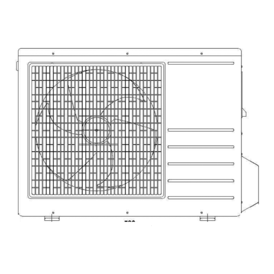
Page 9: Outdoor Unit
3.2 Outdoor Unit MOC-09HDN1-QD0(E) MOC-12HDN1-QC6(E) -
Page 10: Specification
4. Specification Indoor MSC-09HRDN1-QD0(E) MSC-12HRDN1-QC6(E) Outdoor MOC-09HDN1-QD0(E) MOC-12HDN1-QC6(E) Power supply Ph-V-Hz 1,220-240V~,50Hz 1, 220-240V~, 50Hz Capacity Btu/h 9000(3100~11200) 12000(3800~14700) Input 660(300~1100) 970(400~1480) Cooling Rated current 2.9(1.3~4.8) 4.3(1.8~6.5) Btu/w.h, 13.6,4.0 12.4, 3.62 Capacity Btu/h 10000(3300~12300) 13000(4000~15200) Input 690(310~1150) 950(390~1460) Heating Rated current 3.0(1.4~5.0) 4.2(1.7~6.4) Moisture Removal... - Page 11 Indoor MSH-09HRDN1-QD0(E) MSH-12HRDN1-QC6(E) Outdoor MOC-09HDN1-QD0(E) MOC-12HDN1-QC6(E) Power supply Ph-V-Hz 1,220-240V~,50Hz 1, 220-240V~, 50Hz Capacity Btu/h 9000(3100~11200) 12000(3800~14700) Input 660(300~1100) 970(400~1480) Cooling Rated current 2.9(1.3~4.8) 4.3(1.8~6.5) Btu/w.h, 13.6,4.0 12.4, 3.62 Capacity Btu/h 10000(3300~12300) 13000(4000~15200) Input 690(310~1150) 950(390~1460) Heating Rated current 3.0(1.4~5.0) 4.2(1.7~6.4) Moisture Removal Max.
-
Page 12: Refrigerant Cycle Diagram
5. Refrigerant cycle diagram... -
Page 13: Wiring Diagram
6. Wiring diagram 6.1 Indoor Unit MSC-09HRDN1-QD0(E) MSC-12HRDN1-QC6(E) MSH-09HRDN1-QD0(E) MSH-12HRDN1-QC6(E) -
Page 14: Outdoor Unit
6.2 Outdoor Unit MOC-09HDN1-QD0(E) MOC-12HDN1-QC6(E) -
Page 15: Installation Details
7. Installation details 7.1 Wrench torque sheet for installation Outside diameter Torque inch Kg.m Ф6.35 Ф9.52 Ф12.7 Ф15.88 Ф19.05 7.2 Connecting the cables The power cord of connect should be selected according to the following specifications sheet. Grade Unit 7.3 Pipe length and the elevation Standard Max. -
Page 16: Air Purging Of The Piping And Indoor Unit
7.4 Air purging of the piping and indoor unit Required tools: Hexagonal wrench; adjustable wrench; torque wrenches, wrench to hold the joints and gas leak detector. Note: The air in the indoor unit and in the piping must be purged. If air remains in the refrigeration piping, it will affect the compressor, reduce the cooling capacity, and could lead to a malfunction of unit. -
Page 17: Pumping Down (Re-Installation)
7.5 Pumping down (Re-installation) Procedure 1. Confirm that both the 2-way and 3-way valves are set to the opened position. Remove the valve stem caps and confirm that the valve stems are in the opened position. Be sure to use a hexagonal wrench to operate the valve stems. 2. -
Page 18: Re-Air Purging (Re-Installation)
7.6 Re-air purging (Re-installation) Procedure: 1. Confirm that both the 2-way and 3-way valves are set to the closed position. 2. Connect the charge set and a charging cylinder to the service port of the 3-way valve. Leave the valve on the charging cylinder closed. 3. -
Page 19: Balance Refrigerant Of The 2-Way, 3-Way Valves
7.7 Balance refrigerant of the 2-way, 3-way valves Procedure: 1. Confirm that both the 2-way and 3-way valves are set to the open position. 2. Connect the charge set to the 3-way valve’s service port. Leave the valve on the charge set closed. Connect the charge hose with the push pin to the service port. -
Page 20: Evacuation
7.8 Evacuation Procedure: 1. Connect the vacuum pump to the charge set’s centre hose. 2. Evacuation for approximately one hour. Confirm that the gauge needle has moved toward -0.1 Mpa (-76 cmHg) [vacuum of 4 mmHg or less]. 3. Close the valve (Low side) on the charge set, turn off the vacuum pump, and confirm that the gauge needle does not move (approximately 5 minutes after turning off the vacuum pump). -
Page 21: Gas Charging
7.9 Gas charging Procedure: 1. Connect the charge hose to the charging cylinder. Connect the charge hose which you disconnected from the vacuum pump to the valve at the bottom of the cylinder. 2. Purge the air from the charge hose. Open the valve at the bottom of the cylinder and press the check valve on the charge set to purge the air (be careful of the liquid refrigerant). -
Page 22: Operation Characteristics
8. Operation characteristics 8.1 MSC-09HRDN1-QD0(E) Piping Lenth Characteristics(Cooling) Cooling Characteristics 2.58 2.74 2.54 2.68 2.50 2.62 2.46 2.56 2.42 2.50 2.38 2.44 2.34 2.38 2.30 2.32 0.660 0.72 0.655 0.70 0.650 0.68 0.645 0.66 0.640 0.64 0.635 0.62 0.60 0.630 10 11 12 13 14 24 26 28 30 32 35 37 39 41 43... -
Page 23: Msc-12Hrdn1-Qc6(E)
8.2 MSC-12HRDN1-QC6(E) Piping Lenth Characteristics(Cooling) Cooling Characteristics 3.50 3.44 3.38 3.32 3.26 3.20 3.14 3.08 0.97 1.08 0.96 1.04 0.95 1.00 0.94 0.96 0.93 0.92 0.92 0.88 0.84 0.91 10 11 12 13 14 24 26 28 30 32 35 37 39 41 43 Piping Length (m) Outdoor Ambient Temperature( ) ℃... -
Page 24: Msh-09Hrdn1-Qd0(E)
8.3 MSH-09HRDN1-QD0(E) Piping Lenth Characteristics(Cooling) Cooling Characteristics 2.64 2.74 2.60 2.68 2.56 2.62 2.52 2.56 2.48 2.50 2.44 2.44 2.40 2.38 2.36 2.32 0.660 0.72 0.655 0.70 0.650 0.68 0.645 0.66 0.640 0.64 0.635 0.62 0.60 0.630 10 11 12 13 14 24 26 28 30 32 35 37 39 41 43 Piping Length (m) -
Page 25: Msh-12Hrdn1-Qc6(E)
8.4 MSH-12HRDN1-QC6(E) Piping Lenth Characteristics(Cooling) Cooling Characteristics 3.50 3.44 3.38 3.32 3.26 3.20 3.14 3.08 0.97 1.08 0.96 1.04 0.95 1.00 0.94 0.96 0.93 0.92 0.92 0.88 0.84 0.91 10 11 12 13 14 24 26 28 30 32 35 37 39 41 43 Piping Length (m) Outdoor Ambient Temperature( ) ℃... -
Page 26: Electronic Function
9. Electronic function 9.1 Abbreviation T1: Indoor ambient temperature T2: Pipe temperature of indoor heat exchanger T3: Pipe temperature of outdoor heat exchanger T4: Outdoor ambient temperature 9.2 Display function 9.2.1 Icon explanation on indoor display board. MSC-09HRDN1-QD0(E) MSC-12HRDN1-QC6(E) MSH-09HRDN1-QD0(E) MSH-12HRDN1-QC6(E) ①... -
Page 27: Protection
9.2.2 LED display control function. Pressing “LED display” button on remote controller will turn off all displays on indoor unit, while pressing once again, all displays will resume. 9.2.3 Display function in outdoor unit. 9.3 Protection 9.3.1 Three Minutes Delay at restart for compressor. 9.3.2 Temperature protection of compressor top. -
Page 28: Cooling Mode
9.4.3 In this mode, the action of louver is the same as in cooling mode. 9.4.4 The action of auto fan in fan-only mode is the same as auto fan in cooling mode with 24℃ setting temperature. ℃ high medium 9.5 Cooling Mode 9.5.1 In this mode, for the action of 4-way valve please refer the passage 9.10. - Page 29 9.5.3 After start the operation frequency of compressor submits to following rule. When the machine is running and ΔT(=room temp. – setting temp.) changes, the frequency will rise or descend a grade(maximum frequency is F8 in cooling mode, if current frequency is F1, it will not descend even ΔT is reduced) (after 7 minutes).
-
Page 30: Drying Mode
In turbo mode, turning off the units or switching running mode will make the machine quit turbo mode. 9.5.8 Indoor fan operation rule. In cooling mode, indoor fan runs all the time and the speed can be selected as high, medium, low and auto. - Page 31 setting fan speed low fan breeze TEL1 super breeze TEL0 fan stop If the compressor stops caused by room temperature rising, indoor fan will be forced to run 127 seconds with breeze. During this period, anti-cold-wind is disabled. After this, anti-cold –wind function is available. If the machine runs in rating capacity test mode, indoor fan runs with rating speed, and anti-cold-wind is disabled.
- Page 32 ℃ Remark: ΔTcon can be changed among 0, -2,- 4 , the default is 0 ℃ ℃ 9.7.7 Outdoor unit current control in heating mode. comp. pause I3HEAT freq. descends if curr. rises; I2HEAT freq. remains if curr. descends I1HEAT running normally The frequency descending is based on current grade, and judges if descending again or resuming every 2 minutes.
- Page 33 drops more than 5℃. T2 initial record: In anti-cold-wind control, if indoor fan is setting speed, T2 will be recorded after 5 minutes of reaching setting temperature. In anti-cold-wind control, if indoor fan is low speed, breeze or fan pause, the maximum value of T2 will be recorded in this process.
-
Page 34: Auto Mode Function
the machine stops caused by protection in this test mode, after release, it can not turn back to the mode automatically again. Thereinto indoor heat exchanger high temperature protection function is changed as follow: If T2>58℃, compressor frequency will be descended one grade every 20 seconds. When it drops to F2, if T2 is still higher than 58℃... -
Page 35: Action Of 4-Way Valve
9.9.6 The action of forced auto mode is the same as normal auto mode which temperature is 24℃. 9.10 Action of 4-way valve In heating, fan-only, standby or turning off mode, 4-way valve is off, while in cooling or drying mode 4-way valve is on. -
Page 36: Electronic Control Parameter
9.14 Electronic control parameter MSC-09HRD MSC-12HRD Parameter Parameter Explanation RATIFC Cooling Rating Frequency(HZ) RATIFH Heating Rating Frequency(HZ) SLEEPTIMC Sleep Time(Hour) FANCSHIGH Turbo Speed in Cooling (rpm) 1200 1250 FANHSHIGH Turbo Speed in Heating (rpm) 1300 1300 FANCHIGH High Fan in Cooling (rpm) 1150 1250 FANHHIGH... - Page 37 MSH-09HRD MSH-12HRD Parameter Parameter Explanation RATIFC Cooling Rating Frequency(HZ) RATIFH Heating Rating Frequency(HZ) SLEEPTIMC Sleep Time(Hour) FANCSHIGH Turbo Speed in Cooling (rpm) 1200 1250 FANHSHIGH Turbo Speed in Heating (rpm) 1300 1300 FANCHIGH High Fan in Cooling (rpm) 1150 1250 FANHHIGH High Fan in Heating (rpm) 1250...
-
Page 38: Troubleshooting
10. Troubleshooting 10.1 Indoor Unit Error Display Display LED STATUS EEPROM parameter error Indoor / outdoor units communication protection Zero-crossing signal error Fan speed out of control Open or short circuit of outdoor temperature sensor Open or short circuit of room or evaporator temperature sensor IGBT over-strong current protection Over voltage or too low voltage protection Temperature protection of compressor top. -
Page 39: Diagnosis And Solution
Disconnect the power supply, after 1 minute, connect the power supply , turn on the unit with remote controller Does the unit work normally ? Check the wiring between inoor and outdoor unit. Is the connection of L, N, S and Reconnect and retest again GND good? Is the GND connection on... - Page 40 Is the indoor fan motor Repair the connector and connector and connection reconnect good? Is voltage being applied to the fan motor? Indoor PCB is defective. (rang 90v-160v between Replace the indoor PCB. mid pin and N on CN1 Replace the indoor fan motor 10.2.5 E5(Open or short circuit of outdoor temperature sensor) diagnosis and solution.
- Page 41 10.2.8 P1(over voltage or too low voltage protection) diagnosis and solution. Be sure the power supply is Is the power supply good? normal when using the units Replace the outdoor e-box. 10.2.9 P2(temperature protection of compressor top) diagnosis and solution. Is the connection Does compressor Reconnect and retest.
-
Page 42: Characteristic Of Temp. Sensor
11. Characteristic of temp. sensor Temp. Resistance Resistance Resistance KΩ Temp.℃ KΩ Temp.℃ KΩ ℃ 62.2756 14.6181 4.3874 58.7079 13.918 4.2126 56.3694 13.2631 4.0459 52.2438 12.6431 3.8867 49.3161 12.0561 3.7348 46.5725 11.5 3.5896 10.9731 3.451 41.5878 10.4736 3.3185 39.8239 3.1918 37.1988 9.5507 3.0707...
Need help?
Do you have a question about the MSC-09HRDN1-QD0(E) and is the answer not in the manual?
Questions and answers