Graco Reactor E-10 Instructions Manual
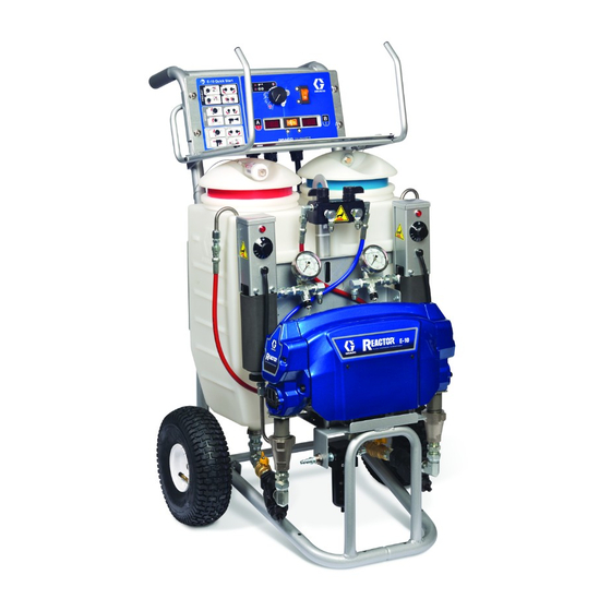
Portable, electric-powered,
1:1 mix ratio proportioner, for use with a
wide variety of coatings, foams, sealants, and
adhesives
Hide thumbs
Also See for Reactor E-10:
- Instructions-parts list manual (74 pages) ,
- Instructions-parts list manual (68 pages) ,
- Instructions-parts list manual (58 pages)
Table of Contents
Advertisement
Instructions - Parts List
For spraying or dispensing 1:1 mix ratio materials, including epoxies,
polyurethane foam, and polyurea coatings. For professional use only.
Not approved for use in European explosive atmosphere locations.
Important Safety Instructions
Read all warnings and instructions in
this manual. Save these instructions.
See page 4 for a list of models and maximum working pressures.
Heated
Package, with
™
Fusion
Gun
Nonheated Package, with 2K
™
Ultra-Lite
Spray disposable mixer
TI6987b
311075R
Gun and Cold
EN
TI6989b
Advertisement
Table of Contents
Troubleshooting

Related Manuals for Graco Reactor E-10


Summary of Contents for Graco Reactor E-10
- Page 1 Instructions - Parts List 311075R For spraying or dispensing 1:1 mix ratio materials, including epoxies, polyurethane foam, and polyurea coatings. For professional use only. Not approved for use in European explosive atmosphere locations. Important Safety Instructions Read all warnings and instructions in this manual.
-
Page 2: Table Of Contents
Pause (Heated Units) ....26 Graco Information ....72 Refilling Tanks . -
Page 3: Related Manuals
Related Manuals Related Manuals The following manuals are for Reactor E-10 components and accessories. Some are supplied with your package, depending on its configuration. Part No. 253422 Compact Disk includes all Reactor E-10 manuals. Manuals are also available at www.graco.com. -
Page 4: Models
Models Models The model no., series letter, and serial no. are located on the back of the Reactor E-10. For faster assistance, please have that information ready before calling Customer Service. Maximum Working Bare Pressure, Proportioner * Electrical Part, Series... -
Page 5: Warnings
Warnings Warnings The following general warnings are for the setup, use, grounding, maintenance, and repair of this equipment. Additional, more specific warnings may be found throughout the body of this manual where applicable. Symbols appearing in the body of the manual refer to these general warnings. When these symbols appear throughout the manual, refer back to these pages for a description of the specific hazard. - Page 6 Warnings WARNING SKIN INJECTION HAZARD High-pressure fluid from gun, hose leaks, or ruptured components will pierce skin. This may look like just a cut, but it is a serious injury that can result in amputation. Get immediate surgical treatment. • Engage trigger lock when not spraying. •...
- Page 7 Graco replacement parts only. • Do not alter or modify equipment. • Use equipment only for its intended purpose. Call your Graco distributor for infor- mation. • Route hoses and cables away from traffic areas, sharp edges, moving parts, and hot surfaces.
-
Page 8: Overview
• Slow circulation results in a higher temper- ature transfer in the heater, so hoses and Reactor E-10 is gravity-fed from 7 gal. (26.5 gun heat up quicker. liter) supply tanks mounted on the unit. The •... -
Page 9: Isocyanate Hazard
• Keep the felt washers in the pump wet-cups the work area. saturated with Graco ISO pump oil, Part No. 217374. The lubricant creates a barrier To prevent contact with isocyanates, appro- between the ISO and the atmosphere. -
Page 10: Keep Components A And B Separate
Keep Components A and B Separate Keep Components A and B Separate NOTICE To prevent cross-contamination of the equip- ment’s wetted parts, never interchange com- ponent A (isocyanate) and component B (resin) parts. Changing Materials • When changing materials, flush the equip- ment multiple times to ensure it is thor- oughly clean. -
Page 11: Component Identification
Component Identification Component Identification Key for F A Supply Tank A M Fusion Air Purge Spray Gun B Supply Tank B N Desiccant Dryer (mounts on supply tank A) C Pump A P Recirculation Tubes D Pump B Q Air Line Inlet (quick-disconnect fitting) E Heater A R Outlet Hose Connections F Heater B... - Page 12 Component Identification Key for F A Supply Tank A N Desiccant Dryer (mounts on supply tank A) B Supply Tank B P Recirculation Tubes C Pump A Q Air Line Inlet (quick-disconnect fitting) D Pump B R Outlet Hose Connections G Fluid Pressure Gauges U Hose Rack and Control Shield H Recirc/Spray and Overpressure Relief Valves...
-
Page 13: Controls And Indicators
Controls and Indicators Controls and Indicators TI7016a . 3. Controls and Indicators (heated unit shown) Motor/Pump Control • Indicator (ST) blinking: If error occurs, STA- TUS indicator will blink 1 to 7 times to indi- Function Knob cate status code, pause, then repeat. See 1 for a brief description of status ABLE Use knob (CF) to select desired function. -
Page 14: Motor Power Switch/Circuit Breaker
Controls and Indicators Motor Power Switch/Circuit Heater Temperature Controls Breaker See F . 4. Control knobs (HC) set tempera- ture of component A and B heaters. Indicator Switch (MP) turns power on to control board lights (HL) turn on when thermostats are heat- and function knob. -
Page 15: Setup
Be sure your installation complies with all National, State and Local Object being sprayed: follow your safety and fire codes. local code. Connect Reactor E-10 to the correct power source for your model. See T 2. Models ABLE Solvent pails used when flushing: with two power cords must be connected to follow your local code. - Page 16 Setup Table 2: Electrical Requirements Model Required Power Source Power Cord Connector 120 V, 1 phase, 50/60 Hz, two Two separate, dedicated cir- Two NEMA 5-15T 15 ft (4.5 m) power cords, cuits rated at minimum of 15 Heated A each 240 V, 1 phase, 50/60 Hz, two Two separate, dedicated cir- Two IEC 320, with...
- Page 17 To avoid electric shock, always unplug both cords before servicing Reactor E-10. Ensure no other high amp loads are connected while running Reactor E-10. To verify separate circuits, plug in Reactor E-10 or a worklight and cycle breakers on and off. Heater Power Motor Power TI7061a .
- Page 18 Setup Heated Units A (ISO) B (RES) A (ISO) TI6988b B (RES) Nonheated TI6990b . 6. Hose Connections 311075R...
- Page 19 Setup Fill wet-cups Fill fluid tanks Keep the felt washers in the pump wet-cups saturated with Graco ISO pump oil, Part No. 217374. The lubricant creates a barrier between the ISO and the atmosphere. NOTICE To prevent cross-contamination of fluids and...
- Page 20 Setup Purge air and flush fluid from Lift hose rack. Remove tank A cover and pour ISO into tank A lines (red side, with desiccant filter in cover). Replace cover Remove both recirculation tubes TI7017a (P) from the tanks and secure each one in a dedicated waste Desiccant filter is blue when fresh, and container.
- Page 21 Setup Turn on Motor Power. When clean fluids exit both recir- culation tubes (P), set function knob to Stop/Park Set Recirc/Spray valves to Recirc. Replace recirculation tubes in supply tanks. On nonheated units, purge the Set function knob to Slow Recirc hoses through the gun without a or Fast Recirc static mixer installed.
-
Page 22: Startup Of Heated Units
Some models heat the fluid, which can cause equipment surfaces to become very hot. To avoid severe burns: • Do not operate Reactor E-10 without all Temporarily set heater control knobs to covers and shrouds in place. maximum setting. •... -
Page 23: Heatup Guidelines
Startup of Heated Units Heatup Guidelines Heat Management Tips • Heaters perform better with lower flow rates The fluids must be circulated from the or smaller mix modules. pumps through the heaters, hoses, and back to the tanks to ensure warm fluids •... -
Page 24: Agents
Startup of Heated Units Heating Foam Resins with c. Fill tanks, page 19. 245 fa Blowing Agents d. Set Recirc/Spray valves to Recirc. New foam blowing agents will froth at tempera- tures above 90°F (33°C) when not under pres- sure, especially if agitated. Never fill the 7 gal. -
Page 25: Spraying/Dispensing
Spraying/Dispensing Spraying/Dispensing Check fluid pressure gauges to ensure proper pressure balance. If imbalanced, reduce pressure of higher component by slightly turning Recirc/Spray valve for that component toward Recirc, until Air is supplied to spray gun with gun piston gauges show balanced pressures. The safety lock or trigger safety lock engaged pressure imbalance alarm (Status Code and gun fluid manifold valves A and B... -
Page 26: Pause (Heated Units)
Pause (Heated Units) Disengage piston safety lock or trigger Set Recirc/Spray valves to Recirc until safety lock. temperature readouts come back up. Fusion 2K Ultra-Lite TI7070a If you stop spraying for more than 2 min- utes when using an impingement mix Test spray onto cardboard or plastic gun, close gun fluid valves A and B. -
Page 27: Pressure Relief Procedure
Pressure Relief Procedure Pressure Relief Shutdown Procedure For longer breaks (more than 10 minutes), use the following procedure. If you will be shut down for more than 3 days, first see Flushing, page 29. Follow all steps of Pressure Relief Pro- Engage piston safety lock or trigger cedure, at left. -
Page 28: Maintenance
Maintenance Maintenance • Check pump wet-cups fluid level daily, page • Generally, flush if you will shutdown for more than three days. Flush more often if material is moisture sensitive and humidity • Do not overtighten packing nut/wet-cup. is high in the storage area, or if material Throat u-cup is not adjustable. -
Page 29: Flushing
Flushing Flushing Set function knob to Stop/Park Flush equipment only in a well-ventilated area. Do not spray flammable fluids. Do not turn on heaters while flushing with flammable solvents. Shut off Heater Power (heated units only). Allow system to cool. •... - Page 30 Flushing To flush gun, refer to gun instruction Set function knob to Stop/Park manual. Purge Gun Hoses (Nonheated Units Only) Wipe out any remaining material from Disconnect hoses from gun and secure the supply tanks. Fill each supply tank back into the tanks for thorough cleaning with 1-2 gal.
-
Page 31: Troubleshooting
Troubleshooting Troubleshooting Status Codes In this example, B side pressure is higher, so Determine the status code by counting the use the B side valve to number of times the status indicator (ST) balance pressures. blinks. Turn Recirc/Spray valve only enough to balance pressure. - Page 32 Troubleshooting Status Code 1 and 2 Settings (Default) 1. Locate switch SW2 on the control board, page 47. TI7023a TI7024a 2. Set the four DIP switches to the desired . 7. DIP Switch (SW2) Settings positions. See F . 7 and T 5 on page ABLE Table 5: Status Code 1 and 2 Settings...
- Page 33 Troubleshooting Status Code 5: Excessive Current Status Code 6: High Motor Draw Temperature Shut off unit and contact distributor before Motor is running too hot. resuming operation. 1. Motor temperature too high. Reduce pres- 1. Locked rotor; motor unable to turn. Replace sure duty cycle, gun tip size, or move Reac- motor, page 51.
-
Page 34: Troubleshooting Chart
Troubleshooting Troubleshooting Chart PROBLEM CAUSE SOLUTION Reactor E-10 does not operate. No power. Plug in power cord. Cycle Motor Power off then on to reset breaker. Motor does not operate. Power turned on with function Set function knob to Stop/Park knob set to a run position. - Page 35 Troubleshooting PROBLEM CAUSE SOLUTION Pressure is higher on one side Pump intake valve partially Clean pump intake valve. See when setting pressure with func- plugged. page 41. tion knob. Air in hose. Fluid is compressible. Purge air from hose. Unequal size hoses or unequal Use matching hoses, or balance hose construction.
- Page 36 Troubleshooting PROBLEM CAUSE SOLUTION A side rich; lack of B side. A side gauge is low. B side restriction downstream of gauge. Check gun check valve screen, mix module, or mix mani- fold restrictor. B side gauge is low. B side material supply problem. Check B side inlet strainer and pump intake valve.
- Page 37 Troubleshooting PROBLEM CAUSE SOLUTION No heat, and heater indicator light Heater Power shut off, or circuit is off. breaker tripped. Cycle Heater Power off then on to reset circuit breaker. Bad thermostat. With power on, check for continu- ity at clicks of heater control knob. To replace thermostat, see 311210.
- Page 38 Troubleshooting 311075R...
-
Page 39: Repair
Repair Repair Before Beginning Repair Removing Supply Tanks Displacement pump repair and parts information is included in manual 311076, which is supplied with your unit. Repairing this equipment requires access to parts which may cause electric shock or 1. See Before Beginning Repair, page 39. other serious injury if work is not performed Relieve pressure, page 27. -
Page 40: Recirc/Spray Valves
Repair Recirc/Spray Valves 2. See F . 8. Disassemble Recirc/Spray valves. Clean and inspect all parts for dam- age. Ensure that the seat (503a) and gas- ket (503b) are positioned inside each valve cartridge (503). 3. Apply PTFE pipe sealant to all tapered pipe 1. -
Page 41: Displacement Pump
If the pump is not generating pressure on the downstroke, intake ball check may be Use dropcloth or rags to protect stuck open. Reactor E-10 and surrounding area from spills. Either of these conditions can be serviced with the pump in place. - Page 42 Repair To Remove Entire Pump Assembly 5. Disconnect fluid inlet (C) and outlet (D) lines. Also disconnect steel outlet tube (16) from heater inlet. 6. Remove pump rod cover (222). Push clip up in back and push pin (217) out. Loosen locknut (218) by hitting firmly right-to-left with a non-sparking hammer.
-
Page 43: Control Module
Repair Control Module Replace Temperature Display and Sensor (Heated Units Only) Change Display Temperature Units (°F/°C) Unit is shipped with temperature displays set to °F. 1. See Before Beginning Repair, page 39. Relieve pressure, page 27. 2. Remove temperature sensor (424): a. - Page 44 Repair 8. Reassemble in reverse order. Mount tem- (P) faces up. Install knob on shaft so slot perature display so Heater Power switch off (S) engages alignment pin in knob. Push (0) position is at left when facing control knob onto shaft against detent spring panel.
- Page 45 Repair Detail of Function Knob/Potentiometer 416a 416a 416a TI7076a 416a *402 *403 *424 410* 424* * These items are not included on the nonheated display. TI6979a . 11. Control Module (Heated Model Shown) 311075R...
- Page 46 Repair Control Board Table 6: Control Board Connectors (see F . 12) Power Bootup Check Board Jack Description There is one red LED (D11) on the Main power from breaker board. Power must be on to check. See Function knob .
- Page 47 Repair Heated Models LINE Heater Heater Power On/Off LINE (20 A Breaker) Single Cord Models Only Heater Black Twin Flat Cable Motor J11 (120 V Black Board) CONTROL Function Yellow Knob BOARD Cycle Yellow Counter Black Status SW2 (see page Indicator 32 to adjust Black Sheath...
-
Page 48: Fluid Heaters (If Supplied)
Repair Fluid Heaters (if supplied) Pressure Transducers Fluid heater repair and parts information is included in manual 311210, which is supplied with heated units. 1. See Before Beginning Repair, page 39. Relieve pressure, page 27. To replace a pressure transducer, see at right. -
Page 49: Drive Housing
Repair Drive Housing B side crankshaft (210) includes the cycle counter magnet (224). When reassembling, be sure to install crank- Removal shaft with magnet on B side. If replacing crankshaft, remove magnet (224). Reinstall magnet in center of off- set shaft on new crankshaft. Position shaft in Park position. -
Page 50: Cycle Counter Switch Replacement
Repair Cycle Counter Switch Replacement B side drive housing cover (227) includes the cycle counter switch (223), mounted in the cover. When reassembling, be sure to install cover with switch on B side. 0.6 in. (15.2 mm) from inside edge 1.0 in. -
Page 51: Electric Motor
Repair Electric Motor Test Motor e. Thread motor power switch harness out bottom of control module and cable If motor is not locked up by pumps, it can be channel, to free motor. tested using a 9 V battery. Open recirculating valves, disconnect J4 or J11 from control board, see F . -
Page 52: Motor Brushes
Repair Motor Brushes Replace brushes worn to less than 1/2 in. (13 mm). Brushes wear differently on each side of motor; check both sides. Brush Repair Kit 287735 is available; kit includes instruction sheet 406582. Motor commutator should be smooth. If not, resurface commutator or replace TI7030a motor. - Page 53 Repair 311075R...
-
Page 54: Parts
Parts Parts Part No. AP9570 or CS9570, 120 V, 15 A, Heated Package Part No. AP9571 or CS9571, 240 V, 10 A, Heated Package Part No. AP9572 or CS9572, 240 V, 20 A, Heated Package TI6988b Proportioner Description AP9570 120 V, 15 A, Heated 249570 249499 249810... - Page 55 Parts Part No. 249806, 120 V, 15 A, Nonheated Package Part No. 249808, 240 V, 10 A, Nonheated Package TI6990b Ref. Part Description Ref. Part Description 249633 HOSE BUNDLE, non-insulated; 249576 PROPORTIONER, nonheated, see page 63 120 V, 15 A; see page 60; 249834 GUN, 2K Ultra-Lite;...
- Page 56 Parts Part No. 249570, 120 V, 15 A, Heated Proportioner Part No. 249571, 240 V, 10 A, Heated Proportioner Part No. 249572, 240 V, 20 A, Heated Proportioner 40 1 (Ref) 1 (Ref) 1 (Ref) TI7068a 63 64 TI6975c 311075R...
- Page 57 Parts Heated Proportioners Ref. Part Description Ref. Part Description 24K995 CORD, 120 V; Model 249570 249582 CART; see page 67 24K997 CORD, 240 V; Model 249571 24L000 TANK, with lid and outlet fitting; 24K996 CORD, 240 V; Model 249572 LDPE; includes item 2a 15G458 CABLE, fan;...
- Page 58 Parts Ref. Part Description 24E555 KIT, temperature sensor 121063 O-RING, fluroroelastomer 66b‡ 123787 FITTING, elbow, 45°; 3/8 jic x 1/4-18 npt 66c‡ 123788 FITTING, elbow, 45°; 5/16 jic x 1/4-18 npt 555561 RING, retaining, 3/8 16C785 HOUSING, thermowell 16C786 MANIFOLD, fluid 16C787 SPACER, sensor 113641 GAUGE, pressure, fluid;...
- Page 59 Parts 311075R...
- Page 60 Parts Part No. 249576, 120 V, Nonheated Proportioner Part No. 249577, 240 V, Nonheated Proportioner 1 (Ref) 40 1 (Ref) 30 (Ref) 1 (Ref) TI7068a TI6981b 311075R...
- Page 61 Parts Nonheated Proportioners Ref. Part Description Ref. Part Description 24K995 CORD, 120 V; Model 249576 249582 CART; see page 67 24K997 CORD, 240 V; Model 249577 24L000 TANK, with lid and outlet fitting; 15G458 CABLE, fan; see page 62 LDPE; includes item 2a CONDUIT, flexible;...
- Page 62 Parts Part No. 287655, 120 V Bare Proportioner Part No. 287656, 240 V Bare Proportioner 201 (Ref) ‡221 208* 209* 210* 215‡ 211* 220‡ 207‡ †212 †213 †214 222‡ 216 †213 220‡ 217 207‡ TI6978a Ref. Part Description Ref. Part Description 24L006 PUMP, displacement;...
- Page 63 Parts Part No. 249499, Insulated Hose Bundle with recirculation lines 302 (Ref) 303 (Ref) TI6991a Ref. Part Description Ref. Part Description 15G342 HOSE, air; 1/4 in. (6 mm) ID; 1/4 249508 HOSE, fluid (component A), npsm (fbe); 35 ft (10.7 m) moisture guard;...
- Page 64 Parts Part No. 24L004, 120 V Heated Display Part No. 24L005, 240 V Heated Display 416a 416a 404 (Ref) TI6979a Ref. Part Description Ref. Part Description 101765 GROMMET 15F984 PLATE 116773 CONNECTOR, plug 24K983 SWITCH, motor or heater 15C866 WIRE, jumper power, with circuit breaker 15G279 LABEL, display 15G386 MODULE, display, temperature;...
- Page 65 Parts Part No. 249537, 120 V Nonheated Display Part No. 249538, 240 V Nonheated Display 416a 416a 404 (Ref) TI6983a Ref. Part Description Ref. Part Description 15G279 LABEL, display 15F984 PLATE 15G053 PLATE, detent 24K983 SWITCH, motor power, with cir- 24L001 KNOB, function;...
- Page 66 Parts Part No. 24L009 Recirculation Manifold, Heated Models Ref. Part Description 24K993 MANIFOLD, recirculation 111763 ELBOW; 1/4 npt (mbe) 239914 VALVE, recirc/spray; includes items 503a, 503b 503a 15E022 . SEAT 503b 111699 . GASKET 503a 224807 BASE, valve 512 503b 187625 HANDLE, valve, drain 111600 PIN, grooved 100721 PLUG, pipe;...
- Page 67 Parts Part No. 249582, Cart TI6976a Ref. Part Description 154636 WASHER, flat 116411 SPRING 116477 WASHER, flat; nylon 116478 WHEEL, pneumatic 101242 RING, retaining GRIP, handle 311075R...
-
Page 68: Suggested Spare Replacement Parts
Suggested Spare Replacement Parts Suggested Spare Replacement Parts Keep the following spare parts on hand to reduce downtime. All Units Heated Units Only Part Description Part Description 24K984 DRYER, desiccant 24K981 DISPLAY, temperature, with sensor 15F895 O-RING, lid, tank 24K980 FUSE, heater over-temperature 24K983 SWITCH, motor or heater power, with cir- 24K978 THERMOSTAT, heater 24K989 HEATER ELEMENT;... -
Page 69: Dimensions
Dimensions Dimensions All Models 44 in. (1118 mm) 26.5 in. (673 mm) 30 in. (762 mm) TI6974a 311075R... -
Page 70: Technical Data
Technical Data Technical Data Maximum fluid working 2000 psi (14 MPa, 140 bar) pressure Electrical requirements Model AP9570, CS9570: 120 Vac, 1 phase, 50/60 Hz, 3500 W; requires two separate, dedicated 15 A circuits Model AP9571, CS9571: 240 Vac, 1 phase, 50/60 Hz, 3800 W; requires two separate, dedicated 10 A circuits Model AP9572, CS9572: 240 Vac, 1 phase, 50/60 Hz, 3800 W;... - Page 71 Technical Data Tank Capacity 7 gal. (26.5 liters) each (nominal) Fluid Outlets Component A (ISO): -5 JIC male Component B (RES): -6 JIC male Fluid Circulation Returns Component A (ISO): -5 JIC male Component B (RES): -6 JIC male Air Inlet 1/4 in.
-
Page 72: Graco Standard Warranty
With the exception of any special, extended, or limited warranty published by Graco, Graco will, for a period of twelve months from the date of sale, repair or replace any part of the equipment determined by Graco to be defective.
Need help?
Do you have a question about the Reactor E-10 and is the answer not in the manual?
Questions and answers